Tài liệu DEVELOPMENT OF AN AUTOUMATIC DATA PROCESSING FOR TRIAXIAL COMPRESSION TEST pdf
Bạn đang xem bản rút gọn của tài liệu. Xem và tải ngay bản đầy đủ của tài liệu tại đây (477.85 KB, 9 trang )
TẠP CHÍ PHÁT TRIỂN KH&CN, TẬP 11, SỐ 03 - 2008
Trang 49
DEVELOPMENT OF AN AUTOUMATIC DATA PROCESSING
FOR TRIAXIAL COMPRESSION TEST
Pham Hong Thom
(1)
, Le Minh Son
(2)
, Phan Tan Tung
(1)
, Nguyen Tan Tien
(1)
(1)University of Technology, VNU-HCM
(2) H.A.I Survey & Construction Company, Hochiminh City
(
Manuscript Received on November 01
st
, 2007, Manuscript Revised March 09
th
, 2008
)
ABSTRACT
:
In triaxial compression test using in soil mechanics, three parameters
need to be monitored: pressure, displacement and drainage volume during testing time. The
drainage volume during the test flows through a vertical pipe which accompanied with a ruler.
Pressure and displacement are indicated by gauges. In manual operation, these parameters
are recorded by examiner after certain duration. This paper studies on developing an
automatic data processing for automatic recording these parameters. A camera is used to
track the drainage level then its volume is determined. Digital pressure sensor and
displacement sensor are used to measure pressure and displacement. Two PIC 18F458s are
used to receive signals from sensors and connect to PC through RS232. The test results in the
required forms are given using software. Experiment has been done to verify the proposed
solution.
1. INTRODUCTION
A typical geotechnical engineering project begins with a site investigation of soil
and
bedrock
on and below an area of interest to determine their engineering properties including
how they will interact with, on or in a proposed construction
. Examining of soil properties,
especially in shear stress, is indispensable to understanding of the area in or on which the
construction will take place. There are two main kinds of the test: direct shear test and triaxial
test.
Direct shear test is used to find the shear strength parameters of soil quickly. In direct
shear test, only the stresses at failure are known, whereas in the triaxial test, the complete state
of stress is assumed to be known at all stages during the test. Therefore, triaxial test is the most
confident test to determine the property of soil although it is quite complex and time-
consuming. There are two types of the test machine: completely automatic machine and
semiautomatic machine. The first one gives exactly the results of experiment and convenience
for examiner but its cost is very high. The second one has lower cost but it is inconvenience
for examiner to get the testing results during test processing because it usually takes two or
three days, even a week to perform the test. At the moment, there is the demand of upgrade the
second one to the first one by using some simple and low cost data acquisition systems using a
personal computer. The data acquisition systems must attain some advantages, such as:
automatic record testing result during test; attain the required accuracy; easy manufacture with
acceptable costs.
There are some commercial automatic testing machines available in domestic market.
However, it cannot be used with the exit testing machine in companies. To be convenient for
users, this study proposes an automatic system which acts like a “plug-in” part with easy
operating functions.
Three parameters need to be monitor are drainage volume, pressure and displacement of
the specimen. A camera sensor, pressure load cell and displacement transducer are used. A
Science & Technology Development, Vol 11, No.03- 2008
Trang 50
controller is designed to drive the camera along the vertical drainage pipe to track the water
level then drainage volume. All signals from sensors are recorded and sent to PC by using
wide-used microcontroller PIC 18F458s. These parameters are then used to predict how the
material will behave in some engineering application. Also by a simple software code, testing
result can be given in a desired report form. Experiment has been done to verify the proposed
solution.
2.THREE AXIAL TEST REQUIREMENTS & AXIAL TEST EQUIPMENT
2.1.Triaxial test requirements
Triaxial tests usually have two applications: confining stress or deviator stress and are
generally classified as one of three conditions of drainage during application of the confining
pressure and loading. The three drainage conditions for testing are the (UU), (CU), and (CD)
referenced below.
31
σσ
+
31
σσ
+
31
σσ
+
Specimen
Fig 1. Types of test
Fig 2. Overall model
Unconsolidated-Undrained (UU): No drainage is allowed during application of the cell
pressure or confining stress and no drainage is allowed during application of the deviator
stress. This test is generally performed on undisturbed saturated samples of fine grained soils
(clay, silt and peat) to measure the in situ undrained shear strength.
Consolidated-Undrained (CU): Drainage
is allowed during application of the confining
stress so that the specimen is fully consolidated under this stress. No drainage is permitted
during application of the deviator stress. This test is performed on undisturbed samples of
cohesive soil, on reconstituted specimens of cohesionless soil and, in some instances, on
undisturbed samples of cohesionless soils which have developed some apparent cohesion
TẠP CHÍ PHÁT TRIỂN KH&CN, TẬP 11, SỐ 03 - 2008
Trang 51
resulting from partial drainage. Generally, the specimen is allowed to consolidate under a
confining stress of known magnitude and is then failed under undrained conditions by
applying an axial load. The volume change that occurs during consolidation should be
measured.
Consolidated-Drained (CD): Drainage is permitted both during application of the
confining stress and the deviator stress, such that the specimen is fully consolidated under the
confining stress and no excess pore pressures are developed during testing. Consolidated
drained tests are performed on all types of soil samples, including undisturbed, compacted and
reconstituted samples.
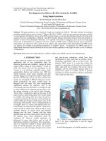
2.2 Axial test equipment
No axial test equipment is made in Vietnam. All companies use the axial test machines
imported from foreign countries. One of the most common test machines used in Vietnam now
is imported from China because of their low price and functions. Overall model is showed
below.
As already stated above, three parameters needed to be determined during axial are
pressure, displacement and drainage volume. In this machine, all of these parameters are not
recorded automatically. The output signal of pressure is electricity and is displayed on led
light. Displacement is defined in mechanical transfer indicator. Drainage volume is monitored
with a vertical pipe. The drainage running out from the test machine is directed to this pipe.
Rely on mark lines on pipe, the examiner can determine drainage volume.
All parameters are recorded by examiner and calculated on paper or on computer.
2.3 Problem statement
During test performance, the examiner must record the parameters continuously. There are
some problems:
(1) The accuracy of results
The accuracy of drainage parameter is not high because the drainage is determined by low
accuracy equipment and recorded by examiner’s eyes.
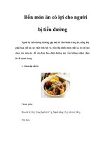
Some results calculated based on graph of parameters. Because the number of parameters
is few, the graph is not smooth enough. In otherwise, the results are determined visually, so the
accuracy of the results is not able to be high.
The time which the examiner records the parameters is different from the real time.
Because the parameters change continuously during test processing and the examiner can not
look at watch and equipments displaying parameter at the same time.
(2) Inconveniences in recording parameters and calculating results
The triaxial test sometimes lasts a week, so the examiner must waste so much time for
recording the parameters.
The examiner also wastes time for entering all parameters and calculating the results on
paper or computer without software packet.
3. SYSTEM DESIGN
The design system must be overcome all problem stated above. Three parameters need to
be monitor are drainage volume, pressure and displacement of the specimen through camera
sensor, pressure load cell and displacement transducer. All signals from sensors are recorded
and sent to a personal computer by using wide-used microcontroller PIC 18F458s. These
parameters are then used to predict how the material will behave in some engineering
Science & Technology Development, Vol 11, No.03- 2008
Trang 52
application. Also by a simple software code, testing result can be given in a desired report
form. The proposed system is given in Fig.3.
Fig 3. Proposed automatic data acquisition system
Fig 4. Drainage volume measuring using camera
3.1 Measurement of drainage volume change
The drainage water running out from compression testing machine, enters a vertical pipe.
There is the color oil above water for easy tracking water level. Camera is controlled to track
water and color oil boundary by nut-screw system. An encoder is assembled in coaxial screw
to determine the water volume.
To perform next test, there are two ways: return the boundary to original position by a
pump or change the moving direction of the boundary by changing the pipe input to the pipe
output.
Test the accuracy of camera
Some suppositions:
Moving direction of the camera and boundary are parallel.
The oil color and the light are stable.
Some features of camera:
The maximum dimensions of camera window are 143x80 pixels.
Set color parameters ( R-G-B) freely to track object.
Return the coordinates of object mass to micro controller of PC.
Tracking color speed is 17 frames/second
Communicate with micro controller or PC through RS232.
TẠP CHÍ PHÁT TRIỂN KH&CN, TẬP 11, SỐ 03 - 2008
Trang 53
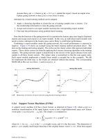
mm1=Δ
cm1
pixelmm 121 ≥=Δ
Fig 5. Accuracy of camera test Fig 6. Error calculating diagram
In the test, camera must be connected to the PC. Rely on the software which supported by
manufacturer, we can view objects which tracked by camera and define their color values and
set tracking color values to camera.
The test was carried out as follows: Put the color point in front of camera, it is about one
centimeter far from camera. Move this point 1mm follow to the vertical of camera (Fig.5). The
number of changing pixels is 12 pixels. Therefore 1 pixel is equivalent to 0,1mm. With the
dimension of pipe using in test machine, 0,1mm is equivalent to 0.01ml. If the controller is
quite good and some noises are not too many, the minimum error can be 0,01ml while the
minimum error which users require is 0,1ml. So the method using camera to track the color is
able to satisfy completely user’s requirements.
Error calculate
During the processing, micro controller sends continuously “TC Rmin Rmax Gmin Gmax
Bmin Bmax \r” (Track Color) to the camera. Rmin, Rmax, Gmin, Gmax, Bmin, Bmax are the
color values of object which are determined by software when the camera is connected to the
computer. Camera will return the coordinates of object mass’s opposite corners. In Fig.6, they
are
),(
111
yxW
,
),(
222
yxW
.
The goal of the controller is that the camera window has the same center with the color
and water boundary. The camera parallels to the boundary, so the coordinates
21
, xx
are
constant. Therefore, the error calculation relies on
21
, yy
only. In Fig.6,
1
y
is always zero.
The error is calculated as follows:
2
2
y
h
e −=
where,
e
: the deviation of the camera window’s center and the boundary between color oil
and water;
h
: height of camera window; and
2
y
: height of tracking object mass.
Communication Diagram
PIC18F458 communicates with camera to verify the position of the boundary and controls
the motor. This motor will drive the camera to follow closely the boundary. At the same time,
PIC18F458 also receives signals from encoder to calculate the drainage volume and sends
these signals to another PIC18F458 through I2C. This PIC18F458 receives three signals: the