The utilization of rice husk silica as a catalyst
Bạn đang xem bản rút gọn của tài liệu. Xem và tải ngay bản đầy đủ của tài liệu tại đây (1.61 MB, 13 trang )
Catalysis Today 190 (2012) 2–14
Contents lists available at SciVerse ScienceDirect
Catalysis Today
journal homepage: www.elsevier.com/locate/cattod
Review
The utilization of rice husk silica as a catalyst: Review and recent progress
Farook Adam a,∗ , Jimmy Nelson Appaturi a , Anwar Iqbal b
a
b
School of Chemical Sciences, Universiti Sains Malaysia, 11800 Penang, Malaysia
Kulliyah of Science, International Islamic University Malaysia, 25200 Kuantan, Pahang, Malaysia
a r t i c l e
i n f o
Article history:
Received 15 October 2011
Received in revised form 18 April 2012
Accepted 21 April 2012
Available online 15 June 2012
Keywords:
Rice husk
Biomass
Silica
Catalyst
Transition metal
a b s t r a c t
In this review article, we report the recent development and utilization of silica from rice husk (RH)
for the immobilization of transition metals and organic moieties. Silicon precursor was obtained in the
form of sodium silicate and as rice husk ash (RHA). Sodium silicate was obtained by direct silica extraction from rice husk via a solvent extraction method while rice husk ash was obtained by pyrolyzing
the RH in the range of 500–800 ◦ C for 5–6 h. Transition metals were immobilized into the silica matrix
via the sol–gel technique while the organic moieties were incorporated using a grafting method. 3(Chloropropyl)triethoxy-silane (CPTES) was used as a bridge to link the organic moieties to the silica
matrix. All the catalysts exhibited good physical and catalytic potential in various reactions.
© 2012 Elsevier B.V. All rights reserved.
Contents
1.
2.
3.
4.
5.
Introduction . . . . . . . . . . . . . . . . . . . . . . . . . . . . . . . . . . . . . . . . . . . . . . . . . . . . . . . . . . . . . . . . . . . . . . . . . . . . . . . . . . . . . . . . . . . . . . . . . . . . . . . . . . . . . . . . . . . . . . . . . . . . . . . . . . . . . . . . . .
Synthesis methodologies . . . . . . . . . . . . . . . . . . . . . . . . . . . . . . . . . . . . . . . . . . . . . . . . . . . . . . . . . . . . . . . . . . . . . . . . . . . . . . . . . . . . . . . . . . . . . . . . . . . . . . . . . . . . . . . . . . . . . . . . . . . .
2.1.
Silica from rice husk: by calcination and solvent extraction . . . . . . . . . . . . . . . . . . . . . . . . . . . . . . . . . . . . . . . . . . . . . . . . . . . . . . . . . . . . . . . . . . . . . . . . . . . . . . . .
2.2.
Modification of silica: incorporation of metal and immobilization of organic . . . . . . . . . . . . . . . . . . . . . . . . . . . . . . . . . . . . . . . . . . . . . . . . . . . . . . . . . . . . . .
Transition metal-based catalysts from rice husk . . . . . . . . . . . . . . . . . . . . . . . . . . . . . . . . . . . . . . . . . . . . . . . . . . . . . . . . . . . . . . . . . . . . . . . . . . . . . . . . . . . . . . . . . . . . . . . . . . . .
3.1.
Chromium . . . . . . . . . . . . . . . . . . . . . . . . . . . . . . . . . . . . . . . . . . . . . . . . . . . . . . . . . . . . . . . . . . . . . . . . . . . . . . . . . . . . . . . . . . . . . . . . . . . . . . . . . . . . . . . . . . . . . . . . . . . . . . . . . . . .
3.2.
Molybdenum . . . . . . . . . . . . . . . . . . . . . . . . . . . . . . . . . . . . . . . . . . . . . . . . . . . . . . . . . . . . . . . . . . . . . . . . . . . . . . . . . . . . . . . . . . . . . . . . . . . . . . . . . . . . . . . . . . . . . . . . . . . . . . . . .
3.3.
Tungsten . . . . . . . . . . . . . . . . . . . . . . . . . . . . . . . . . . . . . . . . . . . . . . . . . . . . . . . . . . . . . . . . . . . . . . . . . . . . . . . . . . . . . . . . . . . . . . . . . . . . . . . . . . . . . . . . . . . . . . . . . . . . . . . . . . . . . .
3.4.
Iron . . . . . . . . . . . . . . . . . . . . . . . . . . . . . . . . . . . . . . . . . . . . . . . . . . . . . . . . . . . . . . . . . . . . . . . . . . . . . . . . . . . . . . . . . . . . . . . . . . . . . . . . . . . . . . . . . . . . . . . . . . . . . . . . . . . . . . . . . . .
3.5.
Cobalt . . . . . . . . . . . . . . . . . . . . . . . . . . . . . . . . . . . . . . . . . . . . . . . . . . . . . . . . . . . . . . . . . . . . . . . . . . . . . . . . . . . . . . . . . . . . . . . . . . . . . . . . . . . . . . . . . . . . . . . . . . . . . . . . . . . . . . . . .
Metal based catalyst from rice husk ash . . . . . . . . . . . . . . . . . . . . . . . . . . . . . . . . . . . . . . . . . . . . . . . . . . . . . . . . . . . . . . . . . . . . . . . . . . . . . . . . . . . . . . . . . . . . . . . . . . . . . . . . . . . . .
4.1.
Friedel–Crafts reaction using iron catalysts . . . . . . . . . . . . . . . . . . . . . . . . . . . . . . . . . . . . . . . . . . . . . . . . . . . . . . . . . . . . . . . . . . . . . . . . . . . . . . . . . . . . . . . . . . . . . . . . . .
4.2.
Rice husk ash supported ruthenium catalyst . . . . . . . . . . . . . . . . . . . . . . . . . . . . . . . . . . . . . . . . . . . . . . . . . . . . . . . . . . . . . . . . . . . . . . . . . . . . . . . . . . . . . . . . . . . . . . . .
4.3.
RHA supported gallium, indium, iron and aluminum for the benzylation of xylenes and benzene . . . . . . . . . . . . . . . . . . . . . . . . . . . . . . . . . . . . . . . .
4.4.
RHA supported aluminum, gallium and indium for the tert-butylation of aromatics . . . . . . . . . . . . . . . . . . . . . . . . . . . . . . . . . . . . . . . . . . . . . . . . . . . . . .
4.5.
Photocatalysis reaction using silica–tin nanotubes . . . . . . . . . . . . . . . . . . . . . . . . . . . . . . . . . . . . . . . . . . . . . . . . . . . . . . . . . . . . . . . . . . . . . . . . . . . . . . . . . . . . . . . . . .
4.6.
Oxidation of benzene over bimetallic Cu–Ce silica catalysts . . . . . . . . . . . . . . . . . . . . . . . . . . . . . . . . . . . . . . . . . . . . . . . . . . . . . . . . . . . . . . . . . . . . . . . . . . . . . . . .
4.7.
Benzoylation of p-xylene on iron silica catalyst . . . . . . . . . . . . . . . . . . . . . . . . . . . . . . . . . . . . . . . . . . . . . . . . . . . . . . . . . . . . . . . . . . . . . . . . . . . . . . . . . . . . . . . . . . . . .
4.8.
Synthesis of nanocrystalline zeolite L from RHA . . . . . . . . . . . . . . . . . . . . . . . . . . . . . . . . . . . . . . . . . . . . . . . . . . . . . . . . . . . . . . . . . . . . . . . . . . . . . . . . . . . . . . . . . . . . .
Organic–inorganic hybrid catalysts . . . . . . . . . . . . . . . . . . . . . . . . . . . . . . . . . . . . . . . . . . . . . . . . . . . . . . . . . . . . . . . . . . . . . . . . . . . . . . . . . . . . . . . . . . . . . . . . . . . . . . . . . . . . . . . . . .
5.1.
One-pot synthesis via sol–gel method . . . . . . . . . . . . . . . . . . . . . . . . . . . . . . . . . . . . . . . . . . . . . . . . . . . . . . . . . . . . . . . . . . . . . . . . . . . . . . . . . . . . . . . . . . . . . . . . . . . . . . .
5.2.
Grafting method . . . . . . . . . . . . . . . . . . . . . . . . . . . . . . . . . . . . . . . . . . . . . . . . . . . . . . . . . . . . . . . . . . . . . . . . . . . . . . . . . . . . . . . . . . . . . . . . . . . . . . . . . . . . . . . . . . . . . . . . . . . . . .
5.3.
Esterification using organic–inorganic hybrid catalysts . . . . . . . . . . . . . . . . . . . . . . . . . . . . . . . . . . . . . . . . . . . . . . . . . . . . . . . . . . . . . . . . . . . . . . . . . . . . . . . . . . . . .
5.4.
Silica from rice husk ash immobilized with 7-amino-1-naphthalene sulfonic acid . . . . . . . . . . . . . . . . . . . . . . . . . . . . . . . . . . . . . . . . . . . . . . . . . . . . . . . . .
5.5.
Silica from rice husk ash immobilized with sulfanilic acid . . . . . . . . . . . . . . . . . . . . . . . . . . . . . . . . . . . . . . . . . . . . . . . . . . . . . . . . . . . . . . . . . . . . . . . . . . . . . . . . . .
∗ Corresponding author. Tel.: +60 46533567; fax: +60 46574854.
E-mail addresses: , farook (F. Adam).
0920-5861/$ – see front matter © 2012 Elsevier B.V. All rights reserved.
/>
3
4
4
4
4
4
5
5
6
7
7
7
7
8
8
8
9
9
9
10
10
11
11
11
12
F. Adam et al. / Catalysis Today 190 (2012) 2–14
6.
7.
Current and future progress . . . . . . . . . . . . . . . . . . . . . . . . . . . . . . . . . . . . . . . . . . . . . . . . . . . . . . . . . . . . . . . . . . . . . . . . . . . . . . . . . . . . . . . . . . . . . . . . . . . . . . . . . . . . . . . . . . . . . . . . .
Closing remarks . . . . . . . . . . . . . . . . . . . . . . . . . . . . . . . . . . . . . . . . . . . . . . . . . . . . . . . . . . . . . . . . . . . . . . . . . . . . . . . . . . . . . . . . . . . . . . . . . . . . . . . . . . . . . . . . . . . . . . . . . . . . . . . . . . . . . .
Acknowledgments . . . . . . . . . . . . . . . . . . . . . . . . . . . . . . . . . . . . . . . . . . . . . . . . . . . . . . . . . . . . . . . . . . . . . . . . . . . . . . . . . . . . . . . . . . . . . . . . . . . . . . . . . . . . . . . . . . . . . . . . . . . . . . . . . . .
References . . . . . . . . . . . . . . . . . . . . . . . . . . . . . . . . . . . . . . . . . . . . . . . . . . . . . . . . . . . . . . . . . . . . . . . . . . . . . . . . . . . . . . . . . . . . . . . . . . . . . . . . . . . . . . . . . . . . . . . . . . . . . . . . . . . . . . . . . . .
3
12
13
13
13
1. Introduction
Silica is the most abundant oxide in the earth’s crust, yet despite
this abundance, silica is predominantly made by synthetic means
for its use in technological applications and it is one of the valuable
inorganic multipurpose chemical compounds [1].
Although silica has a simple chemical formula (SiO2 ), it can exist
in a variety of forms, each with its own structural characteristics, as
well as chemical and physical properties. Silica can exist in the form
of gel, crystalline and amorphous material. Generally, the structure
of SiO2 is based upon a SiO4 tetrahedron, where each silicon atom is
bonded to four oxygen atoms and each oxygen atom is bound to two
silicon atoms. The surface of silica consists of two types of functional
group: silanol groups (Si O H) and siloxane groups (Si O Si). The
silanol groups are the locus of activity for any process-taking place
on the surface, while the siloxane sites are considered non-reactive
[1]. Porous amorphous silica contains three types of silanol on its
surface: isolated, geminal and vicinal [2].
The unequal distribution of the silanols in the matrix, resulting from irregular packing of the SiO4 tetrahedral unit as well
as the incomplete condensation, results in a heterogeneous surface (i.e., non-uniformity in the dispersion of silanol groups) for
synthesized silica. The various silanols can have different adsorption activities and current knowledge indicates that the isolated
silanols are the more reactive species. With increasing temperature of heat treatment, the silica surface becomes hydrophobic
due to the condensation of surface hydroxyl groups resulting in
the formation of siloxane bridges. Commercial silica manufacture
is a multi-step process involving high heat and pressure, making it less cost effective and not very environmentally friendly
[3].
The discovery of mesoporous materials by researchers from the
Mobil Oil Company initiated an intense research effort resulting
in more than 3000 publications, especially in the area of mesoporous materials made from silica. The inertness of silica aided with
the ease of structural tailoring has made it a good inorganic material on which to support other organic and inorganic moieties [4].
In most published reports, the major silica precursors used were
commercially made alkoxysilane compounds such as tetraethylorthosilicate (TEOS), sodium silicate and tetramethylorthosilicate
[5]. Nakashima et al. reported that acute exposure to TEOS can
lead to death. Thus, there is a need to find a safer, less expensive
and more environmentally friendly silica precursor [6]. Naturally
occurring silicas, especially those found in agro waste, can provide
an alternative source to replace commercial silica precursors. Rice
husk saw dust [7], and rapeseed stalk [8] are among the widely studied agro wastes which have been converted into more valuable end
products.
Rice (Oryza sativa L.) is a primary source of food for billions of
people and it covers 1% of the earth’s surface. Globally, approximately 600 million tonnes of rice are produced each year. For every
1000 kg of paddy milled, about 220 kg (22%) of husk is produced
[9]. Rice husk (RH) is therefore an agricultural residue abundantly
available in rice producing countries. Much of the husk produced
from the processing of rice is either burnt or dumped as waste. RH is
composed of 20% ash, 38% cellulose, 22% lignin, 18% pentose and 2%
other organic components [10,11]. Even though some of this husk
is converted into end products such as feedstock [12] and adsorbent [13] most is burnt openly, causing environmental and health
Scheme 1. Various utilizations of the rice husk silica.
problems especially in poor and developing countries. Therefore, it
is very important to find pathways to fully utilize the rice husk.
Silica can be pyrolyzed at elevated temperature to form rice husk
ash (RHA) or it can be extracted from rice husk in the form of sodium
silicate by using a solvent extraction method. In most applications,
rice husk ash is more favorable compared to rice husk. Rice husk
ash is a general term describing all forms of the ash produced from
burning rice husk. In practice, the form of ash obtained varies considerably according to the burning temperature. The silica in the ash
undergoes structural transformations depending on the conditions
(time, temperature, etc.) of combustion. At 550–800 ◦ C amorphous
ash is formed and at temperatures greater than this, crystalline ash
is formed [14]. These types of silica have different properties and
it is important to produce ash of the correct specification for the
particular end use (see Scheme 1). Even though the use of sodium
silicate extracted from rice husk using solvent is still limited, our
studies have shown that it can be utilized for many purposes. Transition metals can easily be supported on silica via sodium silicate
extracted from rice husk. These transformed metal silicates have
good potential as heterogeneous catalysts.
Several researchers have reported different types of synthesis
procedures to prepare mesoporous silica from rice husk for incorporation of metals. Tsay et al. [15] have used aluminum sulfate,
nickel nitrate and aqueous ammonia to prepare Ni/RHA–Al2 O3
via simple impregnation and ion exchange methods. Chen
et al. [16] have reported the preparation Cu/RHA using the
deposition–precipitation method and calcination at 673 K, and the
material was tested for partial oxidation of methanol (POM) to
obtain H2 . Chang et al. [17] described the synthesis of Cu/RHA for
the dehydrogenation of ethanol using copper nitrate trihydrate as
the copper source via an incipient wetness impregnation route.
Due to the high interest in using rice husk silica in adsorption and
catalysis, several studies have been carried out on the synthesis
of mesoporous molecular sieve M41S materials. Grisdanurak et al.
[18] reported the synthesis of MCM-41 mesoporous materials
using CTAB as structure-directing agent (SDA), for the adsorption
4
F. Adam et al. / Catalysis Today 190 (2012) 2–14
of chlorinated volatile organic compounds and photocatalytic
degradation of herbicide (alachlor) [19] and tetramethylammonium [20]. Some researchers had also used direct hydrothermal
synthesis [21] and gasification processes [22] to obtain MCM-41
from rice husk ash. In 2009, Jang et al. [23] synthesized highly
siliceous MCM-48 from RHA using a cationic neutral surfactant
mixture as the structure-directing template. The materials were
used for CO2 adsorption. To date, various parameters such as the
source of silica, effect of surfactant and concentration, temperature
and pH have been considered as major pivotal factors that influence the formation of structural material with the desired pore size
distribution for catalytic studies. In the present article, we review
work performed on the use of silica, obtained from rice husk
either via combustion or by solvent extraction, to support various
transition metals and organic moieties for heterogeneous catalysis.
2. Synthesis methodologies
2.1. Silica from rice husk: by calcination and solvent extraction
Initially, adhered dirt and soil on RH can be removed by washing
with plenty of tap water and rinsing with distilled water. The metallic impurities in RH can be reduced to negligible levels by stirring
with nitric acid [24] or refluxing with hydrochloric acid [17]. Direct
extraction of silica can be performed by stirring the acid treated
RH (after drying) with sodium hydroxide solution. During this process, silica is extracted in the form of sodium silicate together with
other organic moieties, according to the method patented by Adam
and Fua [25]. The sodium silicate obtained is converted to silica by
adding suitable amounts of mineral acid.
Rice husk ash (RHA) can be obtained by pyrolyzing the RH at
temperatures ranging from 500 ◦ C to 800 ◦ C for 5–6 h in a muffle
furnace. The RHA was then dissolved using sodium hydroxide to
obtain sodium silicate. Modifications were undertaken to this procedure according to catalyst preparation parameters. Thus, Chang
et al. [17] pyrolyzed RH at 900 ◦ C for 1 h in a furnace and N2 flow
to obtain a black crude product, which was then pyrolyzed again in
air under the same conditions to obtain a white ash. In 2006, Chandrasekhar et al. [26] studied critically the effect of acid treatment,
calcination temperature and the rate of heating of RH and showed
that these parameters influenced the surface area, reactivity toward
lime and brightness of the ash.
2.2. Modification of silica: incorporation of metal and
immobilization of organic
Silica precipitation from RH and framework transition metal
incorporation was undertaken using the sol–gel technique. A
greater degree of control on the final properties of a catalyst can
be obtained by using the sol–gel technique, which is due to the
ability of the metal precursor to be mixed homogeneously with the
molecular precursor of the support [27]. Metal oxide can be trapped
within the polymerizing gel, permitting precipitation from solution
where the metal ion can occupy neighboring positions in the gel
matrix. Further processing and calcination decomposes the resultant amorphous mixture of metal oxide, hydroxides and metal salts
leading to the formation of an M O M bond [28]. To obtain a structural material, cetyltrimethylammonium bromide (CTAB) as a SDA
was added into the sodium silicate solution. Several researchers
have reported different synthetic routes for preparation of silica
incorporated metal catalysts. Chang et al. [29] incorporated nickel
nitrate into the silica matrix via an ion exchange method. They
also used aqueous copper and chromium nitrate solutions to synthesize Cu/Cr/RHA via incipient wetness impregnation. The metal
salt solution was added slowly to the support and thoroughly
stirred at room temperature. Recently, Chen et al. [16] used
deposition–precipitation to incorporate the copper nitrate in RHA.
In this technique, the metal salt was dissolved in urea solution and
added to RHA to yield a suspension. The suspension was heated at
90 ◦ C and the pH was adjusted to 2–3 by adding nitric acid.
The immobilization of organic moieties was carried out in two
steps. First the CPTES was reacted with the sodium silicate from
RHA in a single step. This led to the formation of RHACCl, which
contained the Cl functional group at the end of the organic chain.
This chlorine functional group was then reacted with the required
organic ligand in a substitution reaction giving rise to the immobilized RHAC-R catalysts, where R is the ligand.
3. Transition metal-based catalysts from rice husk
3.1. Chromium
Our interest in chromium-incorporated silica from rice husk
began with the aim of incorporating chromium into the silica
matrix from rice husk using the sol–gel technique [30]. The catalytic potential of the chromium-loaded catalysts was tested in
the oxidation of cyclohexane, cyclohexene and cyclohexanol. The
as-synthesized chromium–silica catalyst’s surface area was only
0.542 m2 g−1 . Subsequent preparation resulted in a surface area of
1.20 m2 g−1 when it was calcined at 500 ◦ C for 5 h. Surface directing agent was not added during the preparation. These catalysts
contained only Cr(III) species. Calcined chromium–silica catalyst
was observed to be highly hygroscopic. Calcination of the catalyst had improved the selectivity of cyclohexanone but lowered
the selectivity of cyclohexanol in the oxidation of cyclohexane. The
conversion of cyclohexane was 27.13% when the as-synthesized
chromium–silica catalyst was used while the conversion was
12.69% when calcined chromium–silica catalyst was used instead.
Only a slight change was observed in terms of cyclohexene conversion and product selectivity when these catalysts were used. Both
catalysts yielded 100% cyclohexanone selectivity.
By prolonging the aging period and by incorporating surface
directing agent, the surface area could be increased. The surface
area was increased to 3.95 m2 g−1 , and the conversion of cyclohexane was 100% in 6 h. Cyclohexanol and cyclohexanone were
formed in approximately 80:20 ratio. The selectivity of the products
were improved when 4-(methylamino)benzoic acid was added to
the catalyst preparation medium to increase the surface hydrophobicity and the selectivity of cyclohexanol and cyclohexanone was
found to be a ratio of 50:50. The greater hydrophobic character of
chromium–silica catalyst modified with 4-(methylamino)benzoic
acid enhances the interaction of the cyclohexane molecule with the
polar catalyst surface for adsorption and subsequent transformation. The nitrogen atom lone pair in 4-(methylamino)benzoic acid
may form hydrogen bonds with the hydroxyl groups thus retarding
the conversion of cyclohexanol to cyclohexanone. Again only Cr3+
species were identified to be the active site [31].
The effect of pH on the oxidation state of chromium and its
influence in the oxidation of styrene was also studied to identify
which chromium species was more active in the oxidation reaction [32]. The catalysts were prepared at pH 10, pH 7 and pH 3.
At pH 10, only Cr(VI) species were found while at pH 7 and pH
3, Cr(VI) and Cr(III) species co-existed. Chromium loading at pH
10 (7.3 w/w%) was highest, and it was lowest at pH 3 (2.3 w/w%).
At pH 10, the interaction between the negatively charged silicate
particles and positively charged chromium ion is high, thus increasing the possibility of Si O Cr bond formation and the adsorption
of chromium hydroxide, Cr(OH)3 on the silica support. As nitric
acid was further added to reduce the pH, adsorbed Cr(OH)3 can
be re-dissolved into the solution as Cr(III) ions thus resulting in
F. Adam et al. / Catalysis Today 190 (2012) 2–14
5
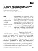
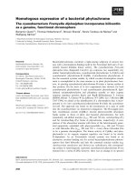
Fig. 1. The SEM image of tungsten–silica catalysts from rice husk prepared at (a) pH 10, (b) pH 7 and (c) pH 3 [37].
lower chromium content. It is hypothesized that the Si O Cr bond
especially in the catalyst prepared at pH 3 was strong enough to
prevent the oxidation of Cr(III) species to Cr(VI) species during calcination. The Cr(VI) species found in the chromium–silica catalyst
prepared at pH 10 and pH 7 was due to the oxidation of Cr(III)
species in Cr(OH)3 [33]. With the aid of cetyltrimethylammonium
bromide (CTAB) as a surface-directing agent, the surface area of
the catalysts was improved to 143–564 m2 g−1 . Higher chromium
containing catalysts yielded lower surface area and vice versa. The
surface of the catalysts was composed of rocky particles. Catalysts
prepared in acidic media were found to be more active in catalyzing the oxidation of styrene using hydrogen peroxide as oxidant.
Benzaldehyde was obtained as the major product. The maximum
conversion of styrene was 99.9% with 63.1% selectivity to benzaldehyde. The higher catalytic activity of the chromium–silica catalysts
prepared in acidic media is related to the higher surface area and
the co-existence of Cr(III) and Cr(VI) species. The rate of hydrogen
peroxide decomposition is increased in acidic reaction media. Recharacterization of the catalyst after reaction indicated a reduction
in chromium content and the chromium detected by AAS analysis was 1.0 w/w% after catalytic testing. However, the leached
chromium species did not contribute significantly to catalytic activity. This was confirmed by leaching tests. The catalyst was found to
be reusable several times without loss of catalytic activity.
3.2. Molybdenum
The same reaction conditions were used to study the effect of
pH on the incorporation of molybdenum into the framework of
silica from rice husk [34]. AAS analysis demonstrated that highest concentration of molybdenum was in the catalysts prepared in
acidic media. Spectroscopic analyses showed the presence of Mo(V)
and Mo(VI) species on the surface of the molybdenum–silica catalyst prepared at pH 3 while only Mo(VI) species was detected on
the surface of the catalyst prepared at pH 10 and pH 7. The pore
system in the catalysts narrowed as the pH was reduced. This is
due to the deposition of molybdenum species into the larger pores
thus resulting in a unimodal pore system. Another reason could be
due to the presence of nitrate ions. At pH 10 and pH 7, the presence of NO3 − ions can shift the equilibrium of the surfactant and
silicate assembly. The NO3 − ion blocks the adsorption of silicate
ions on micelles and delays the formation of the silica/surfactant
mesophases. This can cause incomplete interaction between silicate species and surfactant, resulting in smaller pores being formed
by the template. The larger pores were formed by the agglomeration of silica nanoparticles during the hydrolysis–condensation
process [35,36]. Short ordered pore arrangements existed in the
molybdenum–silica catalysts prepared at pH 10 and started to
deteriorate as the pH was reduced. The SEM images indicate
that the catalysts had rocky particles with spherical surfaces [33].
Molybdenum–silica catalyst prepared at pH 3 showed a higher
styrene conversion and benzaldehyde selectivity compared to the
other two catalysts. Benzaldehyde (Bza) was obtained as the major
product. The conversion was 82.2% and the Bza selectivity was ca.
82.8%. A significant amount of molybdenum leached out from the
support when it was used for the first time. Due to the loss of the
active sites, styrene conversion dropped about 50% when the catalyst was reused. However, the catalysts remained heterogeneous
during consecutive reuse. Re-characterization of the used catalyst
indicated that only Mo(VI) species were found on the surface of
the catalyst. The pore system of the catalyst changed from being
unimodal to bimodal after catalytic reaction due to leaching. The recharacterization of used molybdenum–silica catalyst indicates that
the majority of the molybdenum species was physically adsorbed
on the surface of the catalyst and most probably this was the Mo(V)
species.
3.3. Tungsten
Tungsten species were inserted into the silica matrix using the
same method and conditions as mentioned above [37]. The highest
tungsten concentration was found in the catalysts prepared at pH
3 while the lowest was found in the catalysts prepared at pH 10.
The increasing trend in the immobilization of tungsten content as
the pH was decreased can be related to the interaction between
tungstate species (WO4 )2− and the silicate species. At pH 10, lack
of interaction between these two species due to negative charge
repulsion, yielded catalysts with lower incorporation of tungsten.
The interaction became stronger as the negative character of the
silica oligomers reduced as the pH approached the isoelectric point
6
F. Adam et al. / Catalysis Today 190 (2012) 2–14
(a)
Si
Si
Si
O
O
Si
W
O
(b)
O
O
O
O
O
O
W 6+
O
O
O
Si
Si
O
O
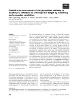
Fig. 2. The structure of (a) isolated tungsten species and (b) isolated (WO4 )2−
species.
of silica (∼pH 2). Thus, the catalysts with higher amounts of tungsten formed under conditions of acidic pH. The SEM image of the
catalyst showed that bright spots started to appear as the acidity of
the catalysts preparation was increased. The images are shown in
Fig. 1. EDX analysis detected a slightly higher tungsten concentration on the bright spots compared to the dark areas as shown in the
SEM images of the catalyst (Fig. 1). Isolated tetrahedral (WO4 )2−
species were the only tungsten species found on the surface of the
tungsten–silica catalyst prepared at pH 10.
UV–vis diffuse reflectance spectroscopic analysis suggested the
presence of different kinds of tungsten species. Isolated tetrahedral (WO4 )2− species, isolated tungsten species or low oligomeric
tungsten oxide species was found in the catalyst prepared at pH 7.
On the other hand, tungsten oxide was detected together with isolated tetrahedral (WO4 )2− species, isolated tungsten species or low
oligomeric tungsten oxide species on the surface of tungsten–silica
catalyst prepared at pH 3.
Isolated tungsten species refers to tungsten ions incorporated
inside the silica framework as shown in Fig. 2(a), whereas the isolated tetrahedral (WO4 )2− species is the species that was formed
on the surface of the catalyst as shown in Fig. 2(b). XRD analysis
indicates that the peak related to the amorphous silica at 2Â = 23◦
started to split into 3 relatively narrow bands with sharp peaks.
New peaks started to appear as well at 2Â = 27◦ , 29◦ , 33◦ , 34◦ , 42◦ ,
47◦ and 48◦ when the pH of the synthesis medium was decreased,
indicating phase segregation leading toward the formation of larger
WO3 crystals on the catalyst surface [38]. The split became more
obvious in tungsten–silica catalyst prepared at pH 7 and pH 3. All
the catalysts have a bimodal pore system. The formation of the
bimodal pore system could be due to the presence of nitrate ions
[39] and due to the tungsten precursor. Normally metal species are
able to speed up the condensation and hydrolysis process. However this did not happen in this case. This can be related to the
bulky size of (WO4 )2− species. The bulky size of (WO4 )2− species
may have prevented the hydrolysis and condensation process from
taking place leading to the formation of different pore sizes. Some
researchers concluded that the FT-IR band around 963 cm−1 in the
tungsten–silica material indicated the incorporation of tungsten
species inside the silica matrix. This band started to diminish when
the acidity was decreased. This indicates the agglomeration of WO3
crystals leading to the formation of extra-framework WO3 on the
support surface, especially in tungsten–silica catalyst prepared in
acidic medium [39,40]. A similar phenomenon was also observed by
us when we incorporated indium into the matrix of silica from rice
husk ash [41]. As the In3+ ion concentration was increased, this band
started to disappear indicating the formation of extra-framework
metal oxide on the surface. The structure of surface active sites of
tungsten–silica catalysts prepared in an acidic medium is shown in
Fig. 3.
The highest styrene conversion of 61.9% and 100% selectivity
toward benzaldehyde was achieved when a tungsten–silica catalyst prepared in acidic medium was used. Higher concentrations of
tungsten and the presence of different kinds of tungsten species
have been identified to be the main factors contributing to the
higher activity of the catalyst prepared at pH 3. The reaction was
Fig. 3. Proposed surface active sites of tungsten–silica catalyst prepared at pH 3
[37].
proposed to be catalyzed by pertungstic acid like intermediates,
with styrene oxide as the intermediate active reagent. A small
amount of tungsten species was found to be leached from the
support and catalyze the reaction homogeneously. The physical
properties of the catalyst were not affected by the loss of tungsten
active sites [38] due to leaching.
3.4. Iron
Iron is a cheap transition metal which is non-toxic to human
health and which has been known to catalyze many organic reactions. When 4-(methylamino)benzoic acid was used as a surface
directing agent it increased the catalyst surface area [42]. The 4(methylamino)benzoic acid was proposed to be attached to the
silica matrix via the nitrogen atom. The formation of the Si N bond
is shown in Fig. 4.
The surface area of the catalyst increased from 267 to 331 m2 g−1
after modification. The increase in surface area was accompanied
by a pore size reduction as expected. The pore size of the catalyst decreased from 9.2 to 6.0 nm. A series of cross-linked lines
arranged in an orderly manner was observed in the TEM image of
4-(methylamino)benzoic acid modified iron–silica catalyst, which
were not present in the TEM image of unmodified catalyst. This
could be due to the amine acting as a template during the syntheses.
Both catalysts were tested in the Friedel–Crafts benzylation
of toluene giving 100% toluene conversion. The mono-substituted
(ortho- and para-) products were found to be the major components
in the product. The unmodified iron–silica catalyst was found to be
less selective to the mono-substituted (ortho- and para-) product
compared to the 4-(methylamino)benzoic acid modified iron–silica
catalyst.
In another study, a purely iron–silica catalyst was found to be
very active in the oxidation of phenol using hydrogen peroxide as
oxidant under mild conditions [43]. Oxidation of phenol using this
catalyst yielded catechol and hydroquinone as the only products.
Two signals related to the Q3 and Q4 silicon centers at −100.4 and
−108.7 ppm were observed when the catalyst was subjected to 29 Si
MAS NMR analysis. Signals related to the spinning side bands were
observed, suggesting the paramagnetic nature of Fe(III) species [44]
which was detected at ca. 10 and −210 ppm.
Oxidation of phenol has been associated with a free radical
mechanism by many authors [45–47]. In this research, we had proposed a non-free radical mechanism. Free radical mechanisms are
known to produce benzoquinone which can later be transformed
to polymeric materials and tar. However these products were not
detected in our study. The intermediate was formed on the surface
of the catalyst assisted by the formation of coordinate bonds by
the reactants to the Fe3+ active sites. The polar nature of the catalyst strongly suggests the reactants were adsorbed on the catalyst
surface via hydrogen bond.
F. Adam et al. / Catalysis Today 190 (2012) 2–14
O
O
Si
O- Na+
Si
O
H3C
7
O
N
H
Strongly
basic
CH3
Si
Si
N
O
+ NaOH
O
Si
O
HO
HO
O
Fig. 4. The formation of Si N bond [42].
3.5. Cobalt
Cobalt catalysts, including nanoparticles, have been prepared
using rice husk silica as the support. Most of the procedures in
the literature were expensive, tedious and time consuming. However, we introduced a simple way to prepare cobalt–silica catalyst
and nanoparticles. The sol–gel method was used to prepare the
cobalt rice husk silica nanoparticles under mild conditions [48].
The cobalt nanoparticles prepared were in the range of 2–15 nm.
The FT-IR spectra of the nanoparticles indicated some similarities with tungsten–silica catalysts mentioned in Section 3.3. The
band at 967 cm−1 disappeared upon cobalt addition into the silica framework. This is due to the presence of cobalt silicate or
hydrosilicate [49]. FT-IR and XRD analyses indicate that the cobalt
nanoparticles comprised Co3 O4 and CoO. Cobalt nitrate decomposed into an intermediate cobalt silicate phase first and later into
Co3 O4 during the drying process. Cobalt rice husk silica nanoparticles prepared via this method exhibit both ferromagnetic and
antiferromagnetic properties. The corresponding saturation magnetization (Ms), coercivity (Hc) and remanent magnetization (Mr)
were noted to be 0.245 emu/g, 340.09 Oe and 0.0115 emu/g respectively. Ms for cobalt–silica nanoparticles was much lower compared
to MbulkCo = 166 emu/g [50]. Decrease in Ms is mostly due to the
smaller cobalt rice husk silica nanoparticles synthesized in this
study. Hard magnet behavior is shown from the hysteresis loop
by showing large Hc (>100 Oe) [51]. The hysteresis of this material
show the presence of a ‘curvature’ shape which indicates ferromagnetic (FM) nature and a ‘straight’ shape which correspond to
antiferromagnetic (AFM) properties. Similar magnetic hysteresis
plot was reported for CoO nanoparticles with size ranging from 10
to 80 nm prepared by sol–gel method [52]. The antiferromagnetic
property of the catalyst is due to the presence of CoO nanoparticles. The Co nanoparticles prepared in this work are proposed to
follow the core–shell model, in which the core is attributed to ferromagnetic metallic and the shell consists of antiferromagnetic CoO
species [53].
4. Metal based catalyst from rice husk ash
4.1. Friedel–Crafts reaction using iron catalysts
The Friedel–Crafts (benzylation) reaction between toluene and
benzyl chloride has been carried out using solid, environmentally
friendly and reusable catalysts (RHA-Fe and RHA-Fe700) [11]. The
mono-substituted benzyltoluene was the major product and both
catalysts yielded more than 92% of the product at 100 ◦ C, in 1 h,
without solvent.
The catalysts show promising activity with almost equal distribution of ortho- and para-isomers. Sixteen minor products
consisting of various di-substituted isomers were also detected.
The ortho-substituted product was present in larger proportion
(49.53%) compared to the para-substituted (46.01%) product when
using RHA-Fe700 as the catalyst. The higher yield of orthosubstituted product was due basically, to the presence of 2
ortho-positions for substitution on the toluene molecule. For RHAFe, about 48.1% and 44.8% of ortho- and para-substituted products
were observed respectively. However, RHA-Fe700 gave a significantly lower yield of the di-substituted products compared to
RHA-Fe.
It was found that the RHA-Fe700 gave slightly higher yield
(∼97.1%) for the mono-substituted product and significantly lower
yield (∼2.8%) for the di-substituted products during the second
reusability studies. However, there was not much difference in the
distribution of the ortho- and para-derivatives.
4.2. Rice husk ash supported ruthenium catalyst
RHA-Ru (as-synthesized) and RHA-Ru700 (calcined at 700 ◦ C)
heterogeneous catalysts were prepared similarly using rice husk
ash silica as the support. The effect of calcination on the surface and bulk structure of the catalyst was investigated and
compared with as-synthesized RHA-Ru catalyst using several
physico-chemical techniques [54]. XRD studies showed RHA-Ru
was largely amorphous (2Â = 22◦ ) with some crystalline peaks
present in RHA-Ru700. Ruthenium was shown to be present in
the form of its dioxide (RuO2 ) in RHA-Ru700. These materials
were further investigated using N2 sorption studies. The isotherm
and hysteresis loop were shown to be of type IV with type
H3 hysteresis respectively for both catalysts according to IUPAC
classification. The BET surface area of RHA-Ru was 65.1 m2 g−1
compared to RHA-Ru700 (10.4 m2 g−1 ). The significant reduction
in the surface area was attributed to a collapse in the pore
structure at 700 ◦ C due to the condensation of adjacent silanol
groups.
Fine needle like structure was seen in the SEM micrographs for
RHA-Ru700. The needles looked like thin flat elongated pieces of
fiber with sharp edges and of nano dimension. The width of the
needles was estimated to be about 200 nm. However, this was not
8
F. Adam et al. / Catalysis Today 190 (2012) 2–14
Table 1
The effect of different xylene isomers on the percentage conversion and product distribution at 80 ◦ C and Xyl/BC molar ratios of 15:1 [55].
Xylene
Time (min)
Selectivity (%)
Time (min)
Selectivity (%)
RHA-Ga
o-Xylene
m-Xylene
p-Xylene
15
23
32.3
97.7
98.7b
97.3
35
42
61
94.6
96.5b
94.8
71.7
46.8
33.3
RHA-In
o-Xylene
m-Xylene
p-Xylene
10.4
13.5
15.9
97.1
98.3
96.4
23.8
24.5
23.5
94.2
96.4b
94.6
103.4
79.7
67.6
RHA-Fe
o-Xylene
m-Xylene
p-Xylene
2.3
3.4
6.0
93.5
97.8b
95.7
4.0
5.5
10.2
92.7
96.3b
93.3
467.4
316.2
179.2
a
b
50% BC conversion
TORa
Catalyst
90% BC conversion
Turnover rate for 50% conversion in mol g−1 s−1 .
Two mono-substituents 2,4-DMDPM and 2,6-DMDPM in a percentage ratio of about 79:21.
observed in RHA-Ru. RHA-Ru in general had a porous matrix due
to the amorphous structure of the catalyst.
4.3. RHA supported gallium, indium, iron and aluminum for the
benzylation of xylenes and benzene
Liquid phase Friedel–Crafts reaction of xylenes (o-Xyl, m-Xyl
and p-Xyl) with benzyl chloride (BC) over the prepared catalyst
(RHA-Fe, RHA-Ga and RHA-In) was carried out at 80 ◦ C [55]. The
differences in activity and selectivity between the xylene isomers
and catalysts are shown in Table 1.
From Table 1, the RHA-Fe showed the highest catalytic activity
whereas RHA-In and RHA-Ga gave higher selectivity to 2,5dimethyldiphenylmethane (2,5-DMDPM) within a shorter time.
The rate of reaction decreased in the following order: RHAFe > RHA-In > RHA-Ga. Iron has a redox potential of +0.77 V while
gallium and indium have a redox potential of −0.44 V. The higher
redox property of iron was expected to play a crucial role for initiating the BC carbocation and showed superior catalytic activity over
the rest. However, the higher activity of RHA-In over RHA-Ga could
be due to the lower amount of non-framework Ga species present
on the surface of RHA-Ga. The catalyst could be reused several times
without significant change in their activity and selectivity [55].
In 2009, Ahmed and Adam [56] used aluminum, gallium and iron
incorporated RHA for the benzylation of benzene (Bz) with BC. Iron
based catalyst, showed excellent activity, whereas RHA-Ga gave
good selectivity toward diphenylmethane (DPM). However, RHAAl was almost inactive in this reaction due to the low redox property
of the Al3+ ion. Among the main advantages of these catalyst was
that there was, no need for calcination after catalyst preparation
and more important was the fact that RHA-Ga and RHA-Fe were
not moisture sensitive and can be handled and stored under normal
conditions.
4.4. RHA supported aluminum, gallium and indium for the
tert-butylation of aromatics
The tert-butylation of some substituted benzenes (toluene and
chlorobenzene) with tert-butyl chloride (TBC) was carried out using
RHA-Al, RHA-Ga and RHA-In at 80 ◦ C [57]. At the initial stage of the
reaction, the tert-butyl cation was formed subsequently via the radical mechanism process, which in turn attacks the benzene ring for
the formation of tert-butyl benzene (TBB) and di-tert-butyl benzene (DTBB) via the SN 1 mechanism (main reaction). However, a
proton elimination reaction (side reaction) also occurred, resulting
in the formation of isobutene dimmers (IBD) and isobutene trimers
(IBT). The extent of these side products was found to decrease
significantly with time, indicating the reversibility of the oligomerization reactions. The catalysts were stable against leaching and
were reusable several times but with an observable drop in catalytic activity. RHA-Ga lost almost 20% of its activity after each run,
whereas, RHA-In was stable until the 3rd run and then lost ∼13%
of its activity at the 5th run. The deactivation was suggested to be
induced by the poisoning effect of the bulky side products that were
strongly adsorbed on the catalyst surface.
Based on the product analysis, a mechanism was proposed for
the tert-butylation of aromatics. It was suggested the reaction
proceeds initially through the radical mechanism for the conversion of TBC to tert-butyl carbocations. However, the carbocations
remained adsorbed on the catalyst, possibly at the framework position replacing the extra-framework Na+ ions forming tert-butoxide.
These tert-butoxide species can either attack the aromatic to form
the tert-butyl products (SN 1) or can undergo elimination reaction
(E1) for the formation of IB monomers. The latter species (i.e., IB)
has extraordinary reactivity toward polymerization under all types
of acidic conditions (i.e., Lewis or Brønsted). It is noteworthy that
the polymerization reaction can be initiated by unconverted tertbutyl carbocation or librated HCl. The capability of the catalyst for
converting the TBC to TB carbocation depends merely on its redox
potential and the number of active sites on its surface. However,
the production of tert-butylated products depends on its ability to
activate the aromatic for the SN 1 reaction as well as the high nucleophilicity of the aromatic, i.e., the presence of electron donating and
not electron withdrawing substituents in the benzene ring [57].
4.5. Photocatalysis reaction using silica–tin nanotubes
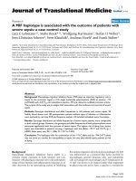
Silica–tin nanotubes (RHA-10Sn) with external diameter of
2–4 nm and internal diameter of 1–2 nm were made by a simple
sol–gel method at room temperature [24]. These nanotubes possess
a hollow inner core with open tube ends (Fig. 5(a)).
The specific surface area of RHA-10Sn was found to be
607 m2 g−1 compared to RHA-silica (315 m2 g−1 ). The increase in
surface area suggests that tin particle were well dispersed within
the silica matrix. No crystalline phase was detected in the high angle
powder XRD analysis. The root-mean-square roughness and height
distribution of RHA-10Sn were found to be 111.5 and 322.6 (nm)
from AFM analysis (Fig. 5(b)). These high values correlate well to
the highly porous tubular material with a high BET surface area.
The photocatalytic activity of RHA-10Sn was studied toward
degradation of methylene blue (MB) under UV-irradiation. As a
control experiment, dark reaction (without UV and catalyst) and
photolysis was conducted to compare with the adsorption and photocatalytic studies. About 96% of MB remained unchanged after
60 min in the dark reaction. The degradation of MB was confirmed
with the reduction in concentration after 960 min. The catalyst
RHA-10Sn gave maximum degradation compared to RHA-silica.
This behavior is due to the wide band gap (Eg = 3.6 eV) of Sn and high
F. Adam et al. / Catalysis Today 190 (2012) 2–14
9
Fig. 5. (a) The TEM micrographs at 110 K, and (b) the 3-D AFM topography image of RHA-10Sn [24].
surface area. The degradation products were identified as inorganic
anions such as nitrate, chloride and sulfate using ion chromatography analysis [24].
4.6. Oxidation of benzene over bimetallic Cu–Ce silica catalysts
A series of mesoporous RHA silica supported Cu–Ce bimetal
catalyst was prepared with cetyltrimethylammonium bromide (as
a template). These catalysts were labeled as RHA-10Cu5Ce, RHA10Cu20Ce, and RHA-10Cu50Ce. TG/DTG analysis of the catalysts
confirmed the complete removal of the template at 773 K. The XRD
pattern showed that RHA and metal incorporated silica catalysts
have amorphous characteristics due to the presence of a broad peak
in the region of 20–30◦ 2Â. However, an observed shift of the diffraction band for RHA–10Cu50Ce, to the 25–35◦ 2Â region can be due
to the poor crystallization of CeO2 with increase in Ce loading [58].
These catalysts were used for a single step oxidation of benzene
with H2 O2 as oxidant and acetonitrile as solvent at 343 K under
atmospheric pressure. The incorporation of two different metals
with silica plays a crucial role in the catalytic activity due to a synergy effect between the metal ions. The equation for the catalytic
oxidation is presented in Scheme 2.
In a typical run, 84.3% benzene conversion and 96.4% phenol selectivity was achieved using 70 mg of RHA-10Cu20Ce at
343 K with other parameters kept constant (H2 O2 = 22 mmol; benzene = 11 mmol; acetonitrile = 116 mmol and reaction time of 5 h).
The high activity and phenol selectivity observed under mild
reaction conditions could be correlated to the enhanced textural
properties such as the specific surface area (329 m2 g−1 ), large pore
volume (0.95 m3 g−1 ) and good dispersion of loaded Cu and Ce ions
which gave more active centers on the amorphous silica. However,
the mono metal ceria (RHA-20Ce) or copper (RHA-10Cu) showed
low activity (23.5% or 47.7%) and phenol selectivity (34.6% or 79.4%)
in comparison to the bimetallic catalysts. This is an indication that
the existence of copper and ceria together in the catalytic system
was necessary for improving the oxidation of benzene.
The oxidation of benzene over different metal loaded catalysts resulted in the same products. However, the selectivity for
phenol was significantly lower and as a consequence, a higher percentage of hydroquinone and 1,4-benzoquinone were obtained.
The catalytic oxidation followed the order RHA-10Cu5Ce < RHA10Cu20Ce < RHA-10Cu50Ce while the order of phenol selectivity
was RHA-10Cu50Ce < RHA-10Cu5Ce < RHA-10Cu20Ce. The catalyst, RHA-10Cu20Ce was found to be the most suitable for this
reaction based on its reusability (up to three recycles with some
loss in catalytic activity) [58].
4.7. Benzoylation of p-xylene on iron silica catalyst
RHA was used to synthesize RHA-5Fe, RHA-10Fe, RHA-15Fe and
RHA-20Fe via the sol–gel technique (pH 5.0) at room temperature
[59]. The acidity of the catalysts was confirmed by pyridine adsorption, and FT-IR spectra show typical bands around 1551 cm−1
and 1565 cm−1 (attributed to Brønsted acid sites) and 1450 cm−1
(attributed to Lewis acid sites). The surface of the catalysts exhibited irregular shaped particles, compared to RHA-silica which
showed agglomerates of spherical particles.
The liquid phase Friedel–Crafts acylation reaction of p-xylene
(p-xyl) with benzoyl chloride (BzCl) was carried out over the assynthesized catalyst. The RHA-10Fe catalyst exhibited the highest
activity for benzoylation of p-xyl. The conversion of BzCl and the
selectivity toward 2,5-dimethylbenzophenone (2,5-DMBP) were
found to be 98.4 and 88.9% respectively at 413 K [59].
As the molar ratio increased from 1:5 to 1:20, (BzCl:p-xyl) the
BzCl conversion also increased. At a molar ratio of 1:20, high conversion of BzCl (86.0%) was observed. At the lower concentration
of BzCl, more active sites of catalyst are available for adsorption,
which results in the formation of active electrophilic benzoylinium
cations that can react with p-xyl. In addition, the selective formation of 2,5-DMBP was not affected as the molar ratio was changed
from 1:5 to 1:20. The benzoylation over different metal loaded catalysts resulted in the same products. However, the selectivity of
2,5-DMBP was reduced slightly after the Fe loading increased more
than 10 wt.%. When the amount of iron increased from 5 to 10 wt.%,
the BzCl conversion increased from 77.7 to 98.4%. However, further
increase of metal loading to 15 and 20 wt.% did not have much effect
on the catalytic activity. The RHA-SiO2 , did not show any activity
for the benzoylation reaction under the same reaction conditions.
Hence, the presence of iron was crucial for boosting the catalytic
activity. The RHA-10Fe was successfully reused several times. However the amount of Fe on the catalyst was found to be reduced
from 7.22 to 4.96 w/w%. A decrease in conversion (42.4%) was also
observed for the second cycle with insignificant decrease in selectivity of 2,5-DMBP (86.8%). The reduction in conversion is due to
the reduced number of metal active sites on the catalyst and may
also be due to the blockage of the pore system by products [59].
The mechanism for the catalysis involves the formation of an
adsorbed BzCl transition species (fast step). This reacts with p-xyl
to form 2,5-DMBP (a bimolecular slow step) with the simultaneous
elimination of HCl [59].
4.8. Synthesis of nanocrystalline zeolite L from RHA
Wong et al. [60] have reported the microscopic investigation
of aluminosilicate zeolite L (structure code LTL) nanocrystals using
10
F. Adam et al. / Catalysis Today 190 (2012) 2–14
Scheme 2. The oxidation of benzene to phenol with the Cu–Ce silica catalyst [58].
RHA as the reactive silica source in a template-free hydrothermal
system. Unlike the conventional cylindrical-shaped zeolite L, the
nanocrystalline zeolite L synthesized from RHA exhibits a onedimensional channel structure with tablet-like features (shorter
c-dimension for better diffusion of products and reactants). The
framework structure of zeolite L consists of cancrinite (CAN) cages
and hexagonal prisms (D6R), alternating to form columns that run
parallel to the c-axis. The research interest in the synthesis of zeolite
L is based on its excellent catalytic properties and wide applications
in host–guest chemistry. Microscopic and spectroscopic analyses
showed that the nucleation of zeolite L took place in the very early
part of the reaction. This rapid formation of LTL nanocrystals is due
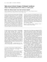
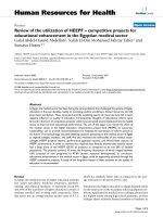
to the use of RHA as the reactive silica source in the precursor solution. Fully crystallized zeolite L was achieved after 24 h resulting
in a product with a mean crystallite size of 210 nm. TEM images
(Fig. 6) confirmed the arrangement of hexagonal pattern, which is
the distinctive feature of zeolite L.
5. Organic–inorganic hybrid catalysts
5.1. One-pot synthesis via sol–gel method
There are various synthesis methods that have been utilized to
attach organic groups to silica surface via the formation of covalent bonds. These are post-synthetic functionalization (grafting),
co-condensation (direct synthesis), production of periodic mesoporous organosilanes (PMO) and “ship-in-bottle” techniques. More
recently, Adam et al. had successfully immobilized chloropropyltriethoxysilane (CPTES) onto the silica network via a one-pot
synthesis using the sol–gel method [61].
The 29 Si MAS NMR spectrum of the resulting organo-silica
product, RHACCl (Fig. 7(a)) shows chemical shifts attributed to Q4
and Q3 [Qn = Si(Osi)n (OH)4−n ], i.e. at ı = −109.92 and −100.65 ppm.
A chemical shift at −65.2 ppm indicates the formation of Si O Si
linkage of CPTES to the silicon atom of the silica via three siloxane
Fig. 6. HR TEM images of solid after heating at (a) 0 h, (b) 4 h, (c) 8 h, and (d) 12 h [60].
F. Adam et al. / Catalysis Today 190 (2012) 2–14
11
Fig. 7. The MAS NMR spectra of RHACCl: (a) the 29 Si MAS NMR spectrum for RHACCl and (b) the 13 C MAS NMR spectrum for RHACCl [61].
bonds, SiO2 ( O )3 Si CH2 CH2 CH2 Cl (T3 ). The chemical shift at
−57.4 ppm was due to two siloxane bonds to the silica matrix,
i.e. SiO2 ( O )2 Si(OH)CH2 CH2 CH2 Cl. The 13 C MAS NMR of RHACCl
(Fig. 7(b)) showed three peaks with chemical shift at 10.37, 26.70
and 47.69 ppm which corresponds to the C1, C2 and C3 carbons
from CPTES respectively [61].
5.2. Grafting method
Grafting is a method to functionalize or modify the surface of
mesostructured silica with organic groups. This process was carried
out using RHACCl with saccharine (Sac) (an artificial sweetening
agent) [62] and melamine (Mela) [63]. The synthesis of silicasaccharine (RHAC-Sac) and silica-melamine (RHAPrMela) catalysts
were carried out using dry toluene and triethylamine (deprotonating agent) under reflux conditions at 110 ◦ C.
EDX confirmed the presence of chlorine (RHACCl; 3.07%), nitrogen (RHAPrMela; 3.65%) and sulfur (RHAC-Sac; 2.29%) respectively.
RHAPrMela exhibited a hollow nanotube like structure and RHACSac showed agglomerated particles.
The results of 29 Si MAS NMR studies for both RHA-Sac
and RHAPrMela indicated the successful immobilization
of these organic molecules on the solid support. Chemical shifts were observed which were attributed to Q4 and
Q3 silicon atoms. A chemical shift at −64.78 and −57.41
(ppm) indicates the formation of Si O Si linkages via
three siloxane bonds, (SiO2 )( O )3 Si CH2 CH2 CH2 Sac and
(SiO2 )( O )3 Si CH2 CH2 CH2 Mela (T3 ) respectively. A chemical shift at −57.4 and −49.16 (ppm) indicates the formation of
two siloxane linkages, i.e. (SiO2 )( O )2 Si(OH)CH2 CH2 CH2 Sac
and (SiO2 )( O )2 Si(OH)CH2 CH2 CH2 Mela (T2 ), to the silica
respectively.
The 13 C MAS NMR of RHA-Sac is shown in Fig. 8(a). Several broad
chemical shifts at 124 and 130 ppm which were easily assignable to
the aromatic carbon at C8, C4, C6 and C9 are apparent. The chemical
shift of the carbon of the lactam ring (C10) can be seen at 160 ppm.
The 13 C MAS NMR for RHAPrMela shows two strong chemical
shifts at 161.52 and 169.67 ppm with their respective spinning side
bands (marked *), indicating that the carbon atoms in melamine are
not equivalent. To prove the existence of the spinning side bands,
the 13 C MAS NMR was recorded at different spin frequencies of
7 MHz (Fig. 8(b)), and 5 MHz (Fig. 8(c)). The result clearly showed
the shifting in the spinning side bands while the main chemical
shifts of the melamine ring were not affected. The chemical shift at
161.52 ppm was assigned to the two carbon atoms with free amine
groups C5 (Scheme 3) which are chemically equivalent. The second
chemical shift at 169.67 ppm was assigned to the carbon atom of the
melamine ring which is bonded to the propyl group C4 (Scheme 3)
through the C3 carbon atom.
5.3. Esterification using organic–inorganic hybrid catalysts
A simple, environmentally friendly, cheap, time-saving and nontoxic catalyst (RHA-Sac [62] and RHAPrMela [63]) was used for the
esterification reaction using ethanol and acetic acid. A conversion of
66% was achieved at 85 ◦ C, and 6 h reaction time with (acid:alcohol)
1:1 molar ratio. The catalyst contains weak basic sites (strong conjugate acid) and the amine group which was believed to play an
important role in this catalytic activity. However, similar catalytic
activity was also obtained when the homogeneous catalyst (Sac)
was used. Minimal loss of catalytic efficiency was observed when
the solid catalyst was reused after regeneration at 150 ◦ C.
The esterification of acetic acid with ethanol was also studied at 85 ◦ C using RHAPrMela. About 73% conversion with 100%
selectivity (ethyl acetate) was achieved in the esterification.
The higher conversion was obtained due to the strong basic
character of the secondary amine in RHAPrMela compared to
RHA-Sac. The esterification of several alcohols were also studied over RHAPrMela. The alcohols studied were 1-propanol
(conversion = 47%), 1-butanol (conversion = 42%), 2-propanol (conversion = 25%), tert-butanol (conversion = 14%) and benzyl alcohol
(conversion = 20%). The conversion generally decreased as the relative molecular mass of the alcohol increased. Primary alcohols
also showed a higher conversion rate compared to the 2◦ or the
3◦ derivatives as shown for propanol and butanol. These variations
could be due to stearic effects as demonstrated for 1-propanol,
2-propanol, tert-butanol and benzyl alcohol. However, it must be
noted that these studies were not carried out at the optimal conditions for the respective alcohols, but rather the conditions for
ethanol was used.
5.4. Silica from rice husk ash immobilized with
7-amino-1-naphthalene sulfonic acid
RHA was functionalized with 3-(chloropropyl)triethoxysilane
and 7-amino-1-naphthalene sulfonic acid to prepare a heterogeneous catalyst for the esterification of n-butyl alcohol with different
mono- and di-acids with strong Brønsted acid sites. Even though
the surface area of the catalyst was only 111 m2 g−1 , it gave a
conversion of 88% and 100% selectivity toward the ester. The
esterification reaction was proposed to take place at the terminal
SO3 H group. The sulfonic group can adsorb the carboxylic acid
and form an eight membered transition state for subsequent attack
12
F. Adam et al. / Catalysis Today 190 (2012) 2–14
Fig. 8. The 13 C MAS NMR spectrum of (a) RHA-Sac [62], (b) RHAPrMela at 7 kHz and (c) RHAPrMela at 5 kHz [63].
by n-butanol. The prepared catalyst was reusable without loss in
catalytic activity [64].
5.5. Silica from rice husk ash immobilized with sulfanilic acid
RHA was immobilized with sulfanilic acid via 3(chloropropyl)triethoxysilane to prepare acidic heterogeneous
catalyst for the solvent free liquid phase alkylation of phenol.
Kinetic studies conducted at 100, 110 and 120 ◦ C showed that the
alkylation of phenol followed a pseudo-first order rate law. The
activation energy deduced from the Arrhenius plot was found to
be 10.4 kcal mol−1 . The hydroxyl group in tertiary butyl alcohol
(TBA) can easily be protonated by the strong Brønsted acid sites
in the catalyst to form the oxonium ion. This oxonium ion can
form a carbocation when water was removed as by-product. The
carbocation formed can attack the ortho- or para-position of phenol
via formation of transition state to give the ortho- or para-alkyl
phenol in a seemingly pseudo-first order reaction. The carbocation
can undergo a proton elimination to form an alkene which can
further attack the ortho- or para-position of phenol as described
by Adam et al. [65].
6. Current and future progress
Catalysts with ordered and oriented pore system and narrow pore size distribution were synthesized recently. Mesoporous
molecular sieves such as MCM-41 incorporated with metals and
organic ligands for catalysis studies have been undertaken. Even
tough, over the past 20 years, there has been a dramatic increase in
the literature on the synthesis, characterization and application of
these molecular sieve materials in catalysis, separation, adsorption
and host–guest chemistry, more research needs to be undertaken
Scheme 3. The prepared catalysts: (a) RHA-Sac [62] and (b) RHAPrMela [63].
F. Adam et al. / Catalysis Today 190 (2012) 2–14
13
Fig. 9. The characterization of RHA-MCM-41: (a) the N2 sorption isotherm, at 77 K. The inset shows the corresponding BJH pore size distribution, (b) the low angle X-ray
diffraction spectra, (c) 29 Si MAS NMR spectra, and (d) TEM micrographs at 450 K [66].
due to the promising application of these materials. Various factors,
such starting material, structure-directing agent (SDA), reaction
parameters (pH, temperature, solvent, etc.) influence the formation
of these mesoporous structure.
RHA-MCM-41 with a high specific surface area (1115 m2 g−1 )
and narrow pore size distribution (PSD) (2.3 nm) with a hexagonal
arrangement of the mesopores has been synthesized using CTAB
as a SDA at 80 ◦ C. The characterization of this material is shown
in Fig. 9. The low angle X-ray diffractogram of RHA-MCM-41 contained four crucial peaks at 2Â 2.43◦ , 4.20◦ , 4.84◦ and 6.30◦ which
can be attributed to the (1 0 0), (1 1 0), (2 0 0) and (2 1 0) diffraction planes [66]. These prominent peaks are clear evidence for the
presence of a highly ordered mesoporous hexagonal phase with
long-range order which was later proved by TEM images.
MCM-41 prepared from rice husk ash was used as a catalyst for
the synthesis of -amino alcohols at 70 ◦ C with toluene as solvent.
A high selectivity of 94.0% of 2-phenylamino-2-phenylethanol (isomer I) and 5.3% of 2-phenylamino-1-phenylethanol (isomer II) was
produced from aminolysis of styrene oxide (SO) [66].
As for the future application of the mesoporous molecular
sieves, MCM-41 can be immobilized with other organic moieties via
post-synthetic methods. The goal is to utilize the organic moieties
as the active site and the solid to provide the support to convert
homogeneous catalysts into heterogeneous ones.
7. Closing remarks
Silica from rice husk obtained through the methods described in
this review has shown great potential to be developed and utilized
in many silica related industries, thus, gradually replacing commercial silica. From the industrial viewpoint, this cheaper silica
precursor has made the mass production of expensive heterogeneous catalysts possible. From the environmental point of view,
the extraction of silica from rice husk is safe and does not harm the
environment.
Acknowledgments
We would like to thank the Malaysian Government for a
Research University Grant (Ac. No. 1001/PKIMIA/811092) and
USM-RU-PRGS grant (1001/PKIMIA/832027) which partly supported this work. We would also like to thank the Malaysian
Ministry of Higher Education for MyBrain15 (MyPhd) scholarship to
J. Nelson and International Islamic University Malaysia for a scholarship to A. Iqbal.
References
[1] D.J. Londeree, Silica–titania composites for water treatment, M. Eng. Thesis,
University of Florida, 2002.
[2] T.W. Dijkstra, R. Duchateau, A. Rutger, van Santen, A. Meetsma, G.P.A. Yap, J.
Am. Chem. Soc. 124 (2002) 9856–9864.
[3] J.A.J. Conner, W.A. Mallow, R.S. Rieber, Patent Genius 6524543.
[4] Z. Xinhong, W. Xiaolai, J. Mol. Catal. A: Chem. 261 (2007) 225–231.
[5] E.A.M.S. Adil, Aluminium, gallium, indium and iron supported onto rice husk
ash silica as catalysts for the Friedel–Craft alkylation reactions of aromatic compounds, PhD Thesis, School of Chemical Sciences, Universiti Sains Malaysia,
Malaysia, 2008.
[6] H. Nakashima, K. Omae, T. Takebayashi, C. Ishizuka, T. Uemura, J. Occup. Health
40 (1998) 270–275.
[7] S.M. Venkat, P.V. Vijay Babu, Desalination 273 (2011) 321–329.
[8] G.W. Seung, Y.C. Byung, G.L. Yoon, J.Y. Duck, B. Hyeun-Jong, Bioresour. Technol.
102 (2011) 5788–5793.
[9] Rice Husk Ash, 2011, available from: />(aaccessed 20.08.2011).
[10] J. James, M.S. Rao, Am. Ceram. Soc. Bull. 65 (1986) 1177–1180.
14
F. Adam et al. / Catalysis Today 190 (2012) 2–14
[11] F. Adam, K. Kandasamy, S. Balakrishnan, J. Colloid Interface Sci. 304 (2006)
137–143.
[12] S. Maiti, S. Dey, S. Purakayastha, B. Ghosh, Bioresour. Technol. 97 (2006)
2065–2070.
[13] T.J. Hyun, K.P. Yoon, S.K. Young, Y.L. Ji, M. Bhagiyalakshmi, Int. J. Greenh. Gas
Control 3 (2009) 545–549.
Husk
Ash
Market
Study,
2011,
available
from:
[14] Rice
(accessed 16.07.2011).
[15] M.-T. Tsay, F.-W. Chang, J. Catal. Commun. 2 (2001) 233–239.
[16] W.-S. Chen, F.-W. Chang, L.S. Roselin, T.-C. Ou, S.-C. Lai, J. Mol. Catal. A: Chem.
318 (2010) 36–43.
[17] F.-W. Chang, H.-C. Yang, L.S. Roselin, W.-Y. Kuo, Appl. Catal. A: Gen. 304 (2006)
30–39.
[18] N. Grisdanurak, S. Chiarakorn, J. Wittayakun, Korean J. Chem. Eng. 20 (5) (2003)
950–955.
[19] S. Artkla, W. Kim, W. Choi, J. Wittayakun, Environ. Asia 1 (2009) 41–48.
[20] S. Artkla, W. Kim, W. Choi, J. Wittayakun, Appl. Catal. B: Environ. 91 (2009)
157–164.
[21] T.R. Gaydhankar, P.N. Joshi, P. Kalita, R. Kumar, J. Mol. Catal. A: Chem. 265 (2007)
306.
[22] S. Chiarakorn, T. Areerob, N. Grisdanurak, Sci. Technol. Adv. Mater. 8 (2007)
111.
[23] H.-T. Jang, Y.K. Park, Y.-S. Ko, J.-Y. Lee, B. Margandan, Int. J. Greenh. Gas Control
3 (2009) 545–549.
[24] F. Adam, J.N. Appaturi, R. Thankappan, M.A.M. Nawi, Appl. Surf. Sci. 257 (2010)
811–816.
[25] F. Adam, H.K. Fua, Production of silica from biogenic material, Malaysian Patent
MY-136715-A (2008).
[26] S. Chandrasekhar, P.N. Pramada, J. Majeed, J. Mater. Sci. 41 (2006) 7926–7933.
[27] C.K. Lambert, R.D.J. Gonzalez, Solid State Commun. 158 (2001) 154–161.
[28] J.Y. Ying, Nanostructured Materials, Academic Press, USA, 2001, pp. 9–10.
[29] F.-W. Chang, M.-T. Tsay, S.-P. Liang, Appl. Catal. A: Gen. 209 (2001) 217–227.
[30] F. Adam, L.F. Cheah, J. Porous Mater. 16 (2008) 291–298.
[31] F. Adam, P. Retnam, A. Iqbal, Appl. Catal. A: Gen. 357 (2009) 93–99.
[32] F. Adam, A. Iqbal, Chem. Eng. J. 160 (2010) 742–750.
[33] Heterogeneous catalysts from rice husk modified with chromium, molybdenum and tungsten: synthesis, characterization and application in styrene
oxidation, Ph.D. Thesis, Universiti Sains Malaysia, 2011.
[34] F. Adam, A. Iqbal, Microporous Mesoporous Mater. 141 (2011) 119–127.
[35] C.J. Brinker, G.M. Scherer, Sol–Gel Science: The Physics and Chemistry of
Sol–Gel Processing, Academic Press, New York, 1990.
[36] X. Wang, W. Li, G. Zu, S. Qiu, D. Zhao, B. Zhong, Microporous Mesoporous Mater.
71 (2004) 87–97.
[37] F. Adam, A. Iqbal, Chem. Eng. J. 117 (2011) 1379–1386.
[38] E. Briot, J. Piquemal, M. Vennat, J. BreÂgeault, G. Chottardb, J. Manoli, J. Mater.
Chem. 10 (2010) 953–958.
[39] W.L. Dai, H. Chen, Y. Cao, H. Li, S. Xie, K. Fan, Chem. Commun. 7 (2003) 892–893.
[40] X.L. Yang, W.L. Dai, H. Chen, J.H. Xu, Y. Cao, He Li, K. Fan, Appl. Catal. A: Gen.
283 (2005) 1–8.
[41] E.A.M.S. Adil, F. Adam, Microporous Mesoporous Mater. 103 (2007) 284–295.
[42] F. Adam, J. Andas, J. Colloid Interface Sci. 311 (2007) 135–143.
[43] F. Adam, J. Andas, Chem. Eng. J. 165 (2010) 658–667.
[44] V. Umamaheswari, W. Bohlmann, A. Poppl, A. Vinu, M. Hartmann, Microporous
Mesoporous Mater. 89 (2006) 47–57.
[45] J.S. Choi, S.S. Yoon, S.H. Jang, W.S. Ahn, Catal. Today 111 (2006) 280–287.
[46] L. Wang, A. Kong, B. Chen, H. Ding, Y. Shan, M. He, J. Mol. Catal. A: Chem. 230
(2005) 143–150.
[47] C. Liu, Y. Shan, X. Yang, X. Ye, Y. Wu, J. Catal. 168 (1997) 35–41.
[48] F. Adam, J. Andas, A.B. Ismail, Open Colloid Sci. J. 4 (12–18) (2011) 1876–5300.
[49] M.S. Ghattas, Microporous Mesoporous Mater. 97 (2006) 107–113.
[50] M. Salavati-Niasari, Z. Fereshteh, F. Davar, Polyhedron 28 (2009) 1065–1068.
[51] K.J. Klabunde, Nanoscale Materials in Chemistry, Wiley Interscience, New York,
2001, p. 198.
[52] L. Zhang, D. Xue, C. Guo, J. Magn. Magn. Mater. 267 (2003) 111–114.
[53] J.S. Hong, J. Pyun, Y.W. Park, C.S. Kim, I. Shin, IEEE Trans. Magn. 45 (2009)
2464–2466.
[54] F. Adam, S. Balakrishanan, P.-L. Wong, J. Phys. Sci. 17 (2) (2006) 1–13.
[55] F. Adam, A.E. Ahmed, J. Chem. Eng. 145 (2008) 328–334.
[56] A.E. Ahmed, F. Adam, Microporous Mesoporous Mater. 118 (2009) 35–43.
[57] A.E. Ahmed, F. Adam, J. Sol–Gel Sci. Technol. 54 (2010) 9–18.
[58] F. Adam, R. Thankappan, J. Chem. Eng. 160 (2010) 249–258.
[59] F. Adam, I.A. Hassan, R. Thankappan, Open Colloid Sci. J. 3 (2010) 15–24.
[60] J.-T. Wong, E.-P. Ng, F. Adam, J. Am. Chem. Soc. 95 (2012) 805–808.
[61] F. Adam, H. Osman, K.M. Hello, J. Colloid Interface Sci. 331 (2009) 143–147.
[62] F. Adam, H. Osman, K.M. Hello, Appl. Catal. A: Gen. 365 (2009) 165–172.
[63] F. Adam, H. Osman, K.M. Hello, Appl. Catal. A: Gen. 382 (2010) 115–121.
[64] F. Adam, K.M. Hello, M.R.B. Aisha, J. Taiwan Inst. Chem. Eng. 42 (2011) 843–851.
[65] F. Adam, K.M. Hello, T.H. Ali, Appl. Catal. A: Gen. 399 (2011) 42–49.
[66] J.N. Appaturi, F. Adam, Z. Khanam, Microporous Mesoporous Mater. 156 (2012)
16–21.