Modeling and simulation of an active robotic device for flexible needle insertion
Bạn đang xem bản rút gọn của tài liệu. Xem và tải ngay bản đầy đủ của tài liệu tại đây (6.38 MB, 143 trang )
MODELING AND SIMULATION
OF AN ACTIVE ROBOTIC DEVICE
FOR FLEXIBLE NEEDLE INSERTION
Nader Hamzavi Zarghani
NATIONAL UNIVERSITY OF SINGAPORE
2009
MODELING AND SIMULATION
OF AN ACTIVE ROBOTIC DEVICE
FOR FLEXIBLE NEEDLE INSERTION
Nader Hamzavi Zarghani
A THESIS SUBMITTED
FOR THE DEGREE OF MASTER OF ENGINEERING
MECHANICAL ENGINEERING DEPARTMENT
NATIONAL UNIVERSITY OF SINGAPORE
2009
This thesis is dedicated to
my parents
Acknowledgments
I wish to thank a number of people who advocate and help me with supportive suggestions and encouraging assertions throughout my Master’s program. My
foremost thank goes to my supervisor Dr. Chui Chee-Kong. I thank him for his
complete understanding and support that carried me through all the difficult times
in my research period, and for his suggestions which helped me to shape my independent research. I should also express my thanks to Dr. Chui Chee-Cheon with
his valuable opinions and suggestions in clarifying difficulties in this research.
I am honored to say my special thanks to all the students and staff in Mechatronics & Control Lab, particularly Dr.Chui’s students whose presence and funloving spirit made the otherwise grueling experience tolerable.
Last but not least, I would like to thank my parents, my brothers, Navid and
Nima, for always being with me when I needed them, and for supporting me through
all these years, and my wonderful girlfriend, Ladan, for tolerating my difficult times
and soothing me by her uncountable valuable supports.
i
Contents
Acknowledgments
i
Abstract
iv
List of Figures
x
List of Tables
xi
List of symbols
xii
1 Introduction
1
1.1
Motivation and Background . . . . . . . . . . . . . . . . . . . . . .
1
1.2
Objectives and Scopes . . . . . . . . . . . . . . . . . . . . . . . . .
4
1.3
Thesis Organization . . . . . . . . . . . . . . . . . . . . . . . . . . .
5
2 Literature Review
2.1
6
Robotics in Surgery and Computer Aided Surgery . . . . . . . . . .
6
2.1.1
Classification of Medical Robots . . . . . . . . . . . . . . . .
8
2.1.2
Application of Medical Robots . . . . . . . . . . . . . . . . .
9
2.2
Percutaneous Insertion Therapy Constraints . . . . . . . . . . . . .
10
2.3
Modeling of Needle Deflection . . . . . . . . . . . . . . . . . . . . .
11
ii
2.3.1
Rigid Needle . . . . . . . . . . . . . . . . . . . . . . . . . . .
11
2.3.2
Flexible Needle . . . . . . . . . . . . . . . . . . . . . . . . .
12
Tissue Deformation Modeling . . . . . . . . . . . . . . . . . . . . .
16
2.4.1
Soft Tissue Biomechanical Properties . . . . . . . . . . . . .
16
2.4.2
Tissue Modeling . . . . . . . . . . . . . . . . . . . . . . . . .
19
2.5
Modeling Needle Insertion Forces . . . . . . . . . . . . . . . . . . .
22
2.6
Tracking of Needle Navigation . . . . . . . . . . . . . . . . . . . . .
29
2.4
3 Theoretical Modeling of Active Needle
32
3.1
Design Considerations of Active Needle . . . . . . . . . . . . . . . .
32
3.2
Modeling of Active Needle . . . . . . . . . . . . . . . . . . . . . . .
33
3.2.1
Kinematic Analysis of Active Needle . . . . . . . . . . . . .
34
3.2.2
Dynamic Analysis of Active Needle . . . . . . . . . . . . . .
43
3.2.3
Lagrangian Equation of Active Needle . . . . . . . . . . . .
47
Implementation of Active Needle . . . . . . . . . . . . . . . . . . .
50
3.3
4 Motion Path Planning and Simulation
4.1
4.2
55
Motion Planning . . . . . . . . . . . . . . . . . . . . . . . . . . . .
55
4.1.1
Identification of the Path . . . . . . . . . . . . . . . . . . . .
56
4.1.2
Modification of the Proposed Path . . . . . . . . . . . . . .
58
4.1.3
Identification of Optimal Path . . . . . . . . . . . . . . . . .
59
Simulation . . . . . . . . . . . . . . . . . . . . . . . . . . . . . . . .
62
iii
5 Active Needle Simulation using SimMechanics
65
5.1
Computer Aided Design of Active Needle . . . . . . . . . . . . . . .
65
5.2
Interfacing Solidworks with SimMechanics . . . . . . . . . . . . . .
66
5.3
Simulation Design Considerations in SimMechanics . . . . . . . . .
68
5.4
Simulation Methods . . . . . . . . . . . . . . . . . . . . . . . . . . .
69
5.5
Simulation Results . . . . . . . . . . . . . . . . . . . . . . . . . . .
71
6 Experiment of an Active Needle Prototype
6.1
6.2
Active Needle Prototype Development . . . . . . . . . . . . . . . .
81
6.1.1
Mechanical Structure . . . . . . . . . . . . . . . . . . . . . .
82
6.1.2
Actuating System . . . . . . . . . . . . . . . . . . . . . . . .
84
6.1.3
DAQ Programming for Driving Motors . . . . . . . . . . . .
87
Experiment Methodology and Results . . . . . . . . . . . . . . . . .
89
6.2.1
Swim-Wave Motion Experiment . . . . . . . . . . . . . . . .
90
6.2.2
Active Needle Prototype Experiment . . . . . . . . . . . . .
91
6.2.3
Experiment Results . . . . . . . . . . . . . . . . . . . . . . .
93
7 Discussion and Conclusion
7.1
81
98
Discussion . . . . . . . . . . . . . . . . . . . . . . . . . . . . . . . .
98
7.1.1
Kinematic and Dynamic Analysis . . . . . . . . . . . . . . .
98
7.1.2
Path Planning and Simulation of Tissue-Needle Interaction
Using SimMechanics . . . . . . . . . . . . . . . . . . . . . .
99
7.1.3
Experiment . . . . . . . . . . . . . . . . . . . . . . . . . . . 101
7.1.4
Application . . . . . . . . . . . . . . . . . . . . . . . . . . . 102
7.2
Future Works . . . . . . . . . . . . . . . . . . . . . . . . . . . . . . 102
7.3
Conclusion . . . . . . . . . . . . . . . . . . . . . . . . . . . . . . . . 103
Reference
105
Appendix
117
iv
Summary
Minimally Invasive Surgery (MIS) is more efficient than open surgery because the
recovery and hospitalization time of MIS is considerably less than conventional
surgical techniques. An active robotic needle is proposed for flexible needle insertion in MIS. The active needle is designed to improve flexibility and reachability
of needle insertion.
With the active needle, we hope to achieve the flexibility to reach otherwise
inaccessible clinical targets. We have investigated the kinematics and dynamics of
the active needle. Based on a flexible swim-wave travelling path, we developed a
new path planning algorithm for the active needle. The needle insertion path could
be modified in accordance with the needle-tissue interaction force. We determine
the optimal needle insertion path using energy minimization method. This is based
on the hypothesis that an optimal path will transfer the minimum energy to the
surrounding tissue and hence, cause less tissue injury.
Simulation based design methodology is used in this study. A computer aided
design model of the active needle is developed using Solidworks. The sophistical
active needle model is then exported to SimMechanics and Matlab for computer
simulation of its interaction with the biological tissue during needle insertion. The
simulation result agrees with the proposed needle insertion path derived from the
path planning algorithm.
v
The active needle prototype has been fabricated for experimental investigation.
The feasibility of the active needle prototype is demonstrated. The active needle
is motorized with two actuators for forward and swim-wave motions. The active
needle comprises the main body and the closed-loop mechanism. The closed-loop
mechanism is a driving system which produces swim-wave motion of the active
needle. This mechanism enables the active needle to be sufficiently small for MIS.
We have found that the active needle can be steered towards the predefined targets
accurately.
Although we have demonstrated theoretically and experimentally the feasibility
of the active needle for flexible needle insertion, further study will be required to
determine the clinical viability of the proposed active needle device.
vi
List of Figures
1.1
Da Vinci Surgical System . . . . . . . . . . . . . . . . . . . . . . .
2
2.1
Mechanical model of viscoelastic material . . . . . . . . . . . . . . .
19
2.2
Force measurement during needle insertion and retraction for liver
tissue . . . . . . . . . . . . . . . . . . . . . . . . . . . . . . . . . . .
23
Needle insertion direction: before puncture, puncture and post puncture . . . . . . . . . . . . . . . . . . . . . . . . . . . . . . . . . . .
25
2.4
The modified Karnopp friction model . . . . . . . . . . . . . . . . .
26
2.5
Shaft force distribution into inhomogeneous phantom . . . . . . . .
28
3.1
Configuration of the active needle model . . . . . . . . . . . . . . .
35
3.2
Workspace of articulated links of the active needle model . . . . . .
36
3.3
Workspace of the active needle; with x translational step . . . . . .
37
3.4
Small diameter active catheter using shape memory alloy coils [93] .
50
3.5
Prototype active needle device . . . . . . . . . . . . . . . . . . . . .
51
3.6
Closed-loop mechanism . . . . . . . . . . . . . . . . . . . . . . . . .
54
4.1
Implementation of the proposed motion path . . . . . . . . . . . . .
59
4.2
Modeling visco-elastic material of soft tissue with Kelvin Model . .
60
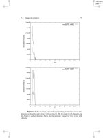
4.3
Simulation result for needle insertion, 1cm increment, until 20cm
depth . . . . . . . . . . . . . . . . . . . . . . . . . . . . . . . . . . .
62
2.3
vii
4.4
Simulation results for insertion depth of 24cm . . . . . . . . . . . .
63
4.5
Simulation results for insertion depth of 30cm . . . . . . . . . . . .
63
5.1
CAD design of active needle prototype . . . . . . . . . . . . . . . .
66
5.2
Diagram of converting of CAD assembly to SimMechanics model . .
67
5.3
Active needle model in SimMechanics software for simulation . . . .
70
5.4
Scope of first joint sensor, forward motion displacement and velocity 71
5.5
Scope of second joint sensor, angle of rotation and angular velocity
72
5.6
Scope of third joint sensor, angle of rotation and angular velocity .
73
5.7
SimMechanics block diagram of active needle with modeling needletissue interaction forces . . . . . . . . . . . . . . . . . . . . . . . . .
74
Displacement of needle tip vs. normal direction to forward motion
of needle, dimensions in mm . . . . . . . . . . . . . . . . . . . . . .
75
Displacement of needle tip vs. direction of needle forward motion,
dimensions in mm . . . . . . . . . . . . . . . . . . . . . . . . . . .
76
5.10 Case I, needle tip displacement vs. time . . . . . . . . . . . . . . .
77
5.11 Case I, needle tip displacement vs. time, displacement along forward
motion direction, dimensions inmm . . . . . . . . . . . . . . . . . .
77
5.12 Case II, needle tip displacement vs. time . . . . . . . . . . . . . . .
78
5.13 Case II, needle tip displacement vs. time, displacement along forward motion . . . . . . . . . . . . . . . . . . . . . . . . . . . . . . .
78
5.14 Case III, needle tip displacement vs. time . . . . . . . . . . . . . .
79
5.15 Case III, needle tip displacement vs. time, direction along forward
motion . . . . . . . . . . . . . . . . . . . . . . . . . . . . . . . . . .
79
5.16 Case IV, needle tip displacement vs. time
. . . . . . . . . . . . . .
80
5.17 Case IV, needle tip displacement vs. time, displacement along forward motion . . . . . . . . . . . . . . . . . . . . . . . . . . . . . . .
80
6.1
82
5.8
5.9
Active needle insertion system . . . . . . . . . . . . . . . . . . . . .
viii
6.2
Main body: physical and CAD model . . . . . . . . . . . . . . . . .
83
6.3
Closed-loop mechanism: physical and CAD model . . . . . . . . . .
84
6.4
Actuating system for active needle prototype . . . . . . . . . . . . .
85
6.5
Stepper motor and driver for forward motion . . . . . . . . . . . . .
86
6.6
Stepper motor and driver for swim wave motion . . . . . . . . . . .
87
6.7
L297 and L298N driving a bipolar stepper motor . . . . . . . . . . .
88
6.8
Circular disk connected to closed-loop mechanism . . . . . . . . . .
89
6.9
Initial position of needle tip before swim-wave motion . . . . . . . .
90
6.10 swim-wave motion under positive rotation of stepper motor . . . . .
91
6.11 Swim-wave motion under clockwise rotation of stepper motor . . . .
92
6.12 Experiment of simultaneous movement to reach pre-defined target,
CCW rotation for swim-wave motion . . . . . . . . . . . . . . . . .
93
6.13 Needle tip position, deviation from predefined target on left-side of
the needle . . . . . . . . . . . . . . . . . . . . . . . . . . . . . . . .
94
6.14 Needle tip position, deviation from predefined target on right-side
of the needle . . . . . . . . . . . . . . . . . . . . . . . . . . . . . . .
95
6.15 Needle tip position in xy plane for counter-clockwise swim wave motion 97
6.16 Needle tip position in xy plane for clockwise swim wave motion . .
97
7.1
Distance error from predefined target- counter-clockwise rotation of
swim wave motion . . . . . . . . . . . . . . . . . . . . . . . . . . . 101
7.2
Distance error from predefined target- clockwise rotation of swim
wave motion . . . . . . . . . . . . . . . . . . . . . . . . . . . . . . . 102
7.3
First link of main body connected to stepper motor . . . . . . . . . 120
7.4
Second link of main body
7.5
Third link of main body . . . . . . . . . . . . . . . . . . . . . . . . 122
7.6
First link of closed-loop mechanism connected to stepper motor . . 123
. . . . . . . . . . . . . . . . . . . . . . . 121
ix
7.7
Second link of closed-loop mechanism . . . . . . . . . . . . . . . . . 124
7.8
Last link of closed-loop mechanism . . . . . . . . . . . . . . . . . . 125
7.9
Pins for connecting closed-loop mechanism to main body . . . . . . 126
7.10 Assembly of closed-loop mechanism . . . . . . . . . . . . . . . . . . 127
x
List of Tables
6.1
Stepper motor unit PK256 . . . . . . . . . . . . . . . . . . . . . . .
85
6.2
Stepper motor unit 103-540-26 STEP-SYN . . . . . . . . . . . . . .
86
6.3
XY displacement of needle tip under actuation of stepper motor,
dimensions in cm . . . . . . . . . . . . . . . . . . . . . . . . . . . .
96
xi
List of symbols
M
Bending moment
c1 , c2
Constant coefficients
C
Coriolis and centrifugal forces
C, S
Cos, sin
V
Cutting force of needle tip
γ
Euler angle about x-axis
β
Euler angle about y-axis
α
Euler angle about z-axis
G
Gravity forces
D
Inertia matrix
J
Jacobian
q
Joint variables
k
Kinetic energy
L
Length of active needle link
E
Modulus of elasticity
I
Moment of inertia
ω
Motion frequency
bn , bp
Negative and positive damping coefficients
Cn , Cp
Negative and positive value of dynamic friction
Dn , Dp
Negative and positive value of static friction
u
Potential energy
xii
M
Resolution of motion
θ2 , θ3 , θ4
Rotational displacement of joints
E1 , E2
Stiffness of tissue
Fa
Sum of nonfrictional forces applied to the system
tp
Time of puncture
∆ v2
Threshold velocity
0
iT
Transformation matrix
λ
Wave length
k
Wave number
xiii
Chapter 1
Introduction
1.1
Motivation and Background
The application of engineering in medicine is promising and demanding. Although
surgery has advanced significantly, surgical outcome is still very much dependent
on the skill of the surgeon. Engineers can develop new devices that could assist
physicians to perform surgeries accurately and less invasively. Medical robotics is an
engineering solution that has improved the capabilities of physicians in healthcare
delivery. Robotics in surgery has been expanding over the past decade despite
concerns of their effectiveness, safety and high cost. [1].
A medical robot can perform a surgical operation continuously, precisely, and
tirelessly for long period with programming. It can place cutting tool at a predefined clinical target precisely. The precision can be improved further when the
medical robot is used with surgical navigation system. A robot can also be programmed to restrict the motion of the surgeon in order to perform operation with
high level of safety [2]. The effectiveness of a surgery is measured by its safety, invasiveness, accuracy, duration and cost. Engineering in medicine, and specifically
robotics in surgery could help the goal of achieving effective surgery.
1
CHAPTER 1. INTRODUCTION
Robotics in surgery includes the usage of robotic and vision systems to interactively assist a medical team both in planning and executing a surgery [3].
These new techniques can minimize the side effects of surgery by providing smaller
incisions, shorter operation time, higher precision, and lower costs than that of conventional methods. Surgical robots are being utilized in remote surgery, minimally
invasive surgery and unmanned surgery. The focus of our research is on minimally
invasive surgery. Less pain and faster recovery can be achieved by minimally invasive surgery. Unlike a minor surgery, minimally invasive surgery requires general
anesthesia before operation.
Figure 1.1: Da Vinci Surgical System
[3]
Well known example of a commercially successful surgical robot is da Vinci
surgical system. Ninety five percent of patients, underwent prostate operations with
this device, came back home after hospitalizing for only one day [4]. In addition
to the da Vinci system, there are other robotic systems developed commercially
and academically for specialized medical procedures from biopsy to retinal surgery.
Early usage of industrial robots was to hold heavy devices at rest during surgical
2
CHAPTER 1. INTRODUCTION
operations. At that time, robots cannot be used for surgery due to safety reasons.
Robodoc is the first robotic system that performed an operation on human to
remove the tissue from the patient in late 1991. After that, a robotic system was
designed in Imperial Collage of London [5], which enhances precision of surgical
operations. In this system, heavy basement with a large workspace is designed to
be situated at rest and a smaller device is connected to the heavy base for the
minimal operation.
Surgical robots can be dichotomized as either passive or active [2]. The passive
type has been used to hold fixtures at an appropriate situation while the active
robot can produce more flexible movements when interacting with the patient.
Active robots are specifically designed for the task. In our research, a novel type
of active robot is introduced for minimally invasive surgery, using active robotic
elements.
Our research concerns modeling needle insertion into a soft tissue and simulating path planning. Three major challenges in needle insertion are deformations,
uncertainty and optimality [6].
Deformation: When the needle is inserted into a soft tissue, soft tissue will deform
due to its interaction with the needle. Therefore, in order to precisely and
successfully steer the needle into the target, soft tissue deformation should
be considered for percutaneous insertion surgery.
Uncertainty: The needle might not perform action commands accurately with
complete certainty in a clinical operation. Clinicians have to make provision
for available uncertainties, such as the flexure of the needle due to its interaction with the tissue, to insert the needle into the target with highest possible
accuracy.
3
CHAPTER 1. INTRODUCTION
Optimality: There could be more than one possible path for the needle to reach
the clinical target. Among these possible paths, the optimal path should be
selected in accordance with an optimization criteria. Energy optimization is
the optimization criterion used in our research.
Our research addresses new flexible robotic system which can follow complex
paths. The reachability of the robotic system is improved with the mechanical
structure of the flexible needle. A closed-loop mechanism is designed to transfer
motion from the base joint to revolute joints. This mechanism is small in size
since the actuating system of the mechanism is set on the first link of the needle.
However, kinematic analysis of the system becomes complex. This research also
investigates path planning and simulation of needle-tissue interaction in order to
find an optimal path for needle insertion. Experiment of the active needle prototype
investigates the accuracy of needle insertion towards predefined targets.
1.2
Objectives and Scopes
A new surgical robotic needle known as the active needle, is proposed to improve
the accuracy of needle insertion during surgery. This study focuses on the modeling
and simulation of the active needle. By modeling the needle using fish-like robotic
elements, path planning algorithm for the active needle is derived and validated
with simulation result of needle-tissue interaction. Experiment is conducted to
investigate the feasibility of developing an active needle prototype.
The scope of this research covers the following issues:
• Kinematic and dynamic analysis of the active needle,
• Needle insertion; path planning and dynamics,
4
CHAPTER 1. INTRODUCTION
• Optimization of required energy for needle steering,
• Simulation of active needle,
• Experiment of active needle prototype.
1.3
Thesis Organization
This thesis describes kinematic analysis, dynamic analysis, path planning, simulation, implementation and experiment of the active needle model. A complete research review on the needle insertion is presented in Chapter 2. Chapter 3 presents
kinematic, dynamic analysis and implementation of the active needle. In Chapter
4, path planning, identification of path parameters and optimization of the bending energy are investigated. Chapter 5 covers simulation analysis of the active
needle’s trajectory with SimMechanics. In Chapter 6, accuracy of needle insertion
is investigated by conducting experiment with the active needle prototype. Finally,
discussion on results and future works for this research are summarized in Chapter
7.
5
Chapter 2
Literature Review
Many surgical robots have been used to perform or assist needle insertion during
surgery. Problems of needle insertion including reachability due to uncertainty of
needle steering have been extensively investigated [7–11]. However, an engineering
solution that can effectively address the complex problems of needle insertion during surgery has yet to be found. We have proposed to overcome these problems
using computer modeling and simulation after an extensive review of the existing
literature.
2.1
Robotics in Surgery and Computer Aided
Surgery
Computer Aided Surgery(CAS) is defined as a set of methods for preplanning,
performing surgical intervention and post-operative procedures [12]. Extracting
3D model from medical images in late 1980s is the early application of CAS for
surgical simulation [13]. CAS has three different phases for planning and operation.
6
CHAPTER 2. LITERATURE REVIEW
These three phases are: pre-operative planning, intra-operative intervention, postoperative assessment. Robotics in surgery can be integrated with these phases of
CAS.
In computer assisted robotic surgery, computer technology is utilized for planning, executing and following up of surgical procedures. In this study, surgical
robots are not considered to replace the surgeon, but to provide the surgeon with
a new set of versatile tools that can extend his or her ability to treat patients.
In our terminology, medical robotic systems serve as surgical assistants that work
cooperatively with surgeons. Computer integrated robot assisted surgery includes
the concept that the robot itself is just one element of CAS, which is designed to
assist a surgeon in carrying out a surgical procedure [14].
The robot is used directly in the intervention aspects of the intraoperative
phase. However, when a robot is to be used, the planning aspect can also include a
computer simulation sequence of robot motions. When the surgeon is satisfied that
the sequence is correct and the robot will not impinge on the patient or adjacent
equipment, then the motion sequence can be downloaded directly to the robot
controller.
In the intraoperative phase, it is necessary to fix the robot with reference to the
patient and then register the robot to specific markers or fiducials on the patient,
usually by touching the robot tip to the markers [2]. These same fiducials will have
been observable in the pre-operative imaging and three-dimensional models, and
so this process can register the current patient fiducial location to that on the preoperative images and models, as well as to the intraoperative robot location. The
fiducials are usually small screws inserted into the bone in the orthopaedic surgery
or are small discs stuck to the skin, e.g. over boney prominences in neurosurgery.
To ensure that the robot is being correctly employed, an intraoperative display
of robot motions is required to guide the surgeon. The robotic display provides
7
CHAPTER 2. LITERATURE REVIEW
a three-dimensional schematic of the correct position of the tool superimposed
over simplified views of the tissue. These simplified schematic views are necessary
for real-time viewing of often complex motions. Simple schematic are required
for robotic display with only basic robot parameters on the screen, because the
surgeon can perform properly in an emergency [15]. In an emergency, it may be
necessary to abort the robotic procedure and it must be ensured that at all times
it is possible to finish the surgery using a safe manual procedure. However, full
diagnostics should be available on the screen when the full status of procedure is
required to judge for next motion of robotic device.
An immediate assessment phase is usually required post-operatively. This requires that the robot can be readily removed and the patient unclamped so that the
patient can be moved around. Rapid robot removal is also essential for safety reasons, so that if the robot malfunctions, it can be quickly removed and the procedure
completed manually. In order to perform further action based on the assessment, it
will be necessary to re-clamp the patient and reposition and re-register the robot.
Clinicians have been referring to CAS as medical robotics [16]. Medical robotics
have vision from medical imaging as well as intelligence through computing. The
market of medical robotics is expanding worldwide and is employing different technologies including surgical robots, control, imaging, surgical simulators, safety devices for computer-assisted surgery. CAS is using novel technologies to improve
accuracy and precision and also to reduce invasiveness and cost of surgery [17].
2.1.1
Classification of Medical Robots
Surgical robots can be classified with respect to their technology basis [2]. The
powered robot can be used in either passive mode or active mode to perform an
operation. Using powered robots passively was the earliest applications of surgical
8
CHAPTER 2. LITERATURE REVIEW
robots as a means of holding fixtures at an appropriate location, so that the surgeon
could insert tools into the fixture [18]. These systems have the potential to provide
a more stable platform to be more accurate for deep-seated tumors than equivalent
camera-based localizers or localizers based on unpowered manipulator arms. A
powered robot can be used to interact with the patient actively and create more
complex motions potentially than that of a powered robot used passively. Most
active robots have been developed specifically for the task and safety level has been
set high.
2.1.2
Application of Medical Robots
Probably the largest sales of a commercial system for robotic surgery have been in
the area of the manipulation of laparoscopes, mostly for abdominal, minimally invasive surgery [19,20]. There are also many clinical operations which require percutaneous diagnosis and therapies. In these operations, a thin device(needles, catheters,
and ablation probes) will be inserted into a non-homogenous tissue. Application
for percutaneous insertion are blood sampling [21], biopsy [22], brachytherapy [23]
and neurosurgery [24].
The accuracy of an operation may vary for different applications. In eye, brain
and ear procedures micro-millimeter is the required accuracy while placement accuracy for biopsy, brachytherapy and anesthetic in millimeter scale is satisfactory.
It has been revealed that imaging misalignments, imaging deficiency, target displacement due to tissue deformation, needle deflection and target uncertainty are
the main reasons for missing the target [25–30].
9