- Trang chủ >>
- Khoa Học Tự Nhiên >>
- Vật lý
DISTRIBUTION OF THE LASER INTENSITY AND THE FORCE ACTING ON DIELECTRIC NANO PARTICLE IN THE 3d OPTICAL TRAP USING COUNTER PROPAGATING PULSED LASER BEAMS
Bạn đang xem bản rút gọn của tài liệu. Xem và tải ngay bản đầy đủ của tài liệu tại đây (688.72 KB, 7 trang )
Proc. Natl. Conf. Theor. Phys. 35 (2010), pp. 243-249
DISTRIBUTION OF THE LASER INTENSITY AND THE FORCE
ACTING ON DIELECTRIC NANO-PARTICLE IN
THE 3D-OPTICAL TRAP USING COUNTER-PROPAGATING
PULSED LASER BEAMS
HO QUANG QUY
Academy of Military Science and Technology; Email:
BUI SY KHIEM
Second High Secondary School of Tinh Gia, Thanh Hoa
NGUYEN THI HA TRANG, MAI VAN LUU, CHU VAN LANH, DOAN HOAI SON
University of Vinh
Abstract. In this article the 3D-optical trap using counter-propagating laser beams is proposed.
The expressions described the space-distribution of laser total intensity, and related optical forces
acting on the dielectric nano-particle are derived. Some simulated results are presented and discussed.
I. INTRODUCTION
Up to now, the optical trap using one Gaussian beam [1, 2] and two counterpropagating Gaussian pulsed beams [3, 4, 5] are interested in many works. Those traps
will be used for manipulation particles in stable spicement, only, but not for particles in
3D-space embedded by gas or fuild. In this case it is needed to use three pairs of counterpropagating laser beams. This optical trap is called 3D-trap, which is used to design the
atom cooler [6]. In this article we present the distribution of the total intensity and the
optical forces acting on dielectric nanoparticle.
II. DISTRIBUTION OF TOTAL INTENSITY
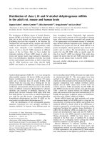
A 3D-trap designed from three pairs of counter-propagating pulsed Gaussian beams
(PGB) is presented in Fig.1a. For example, the pair of PGB propagating in Z-direction is illustrated in Fig.1b. We consider the optical forces are induced by two counter-propagating
PGBs acting on a Rayleigh dielectric particle, i.e. the dimension of particle is more smaller
than laser wavelength (a << λ). The polarization direction of the electric field is assumed
to be along the x-axis.
244
H. Q. QUY, B. S. KHIEM, N. T. H. TRANG, M. V. LUU, C. V. LANH, D. H. SON
Fig. 1. (a) Sketch of 3D-Optical trap: 1- Laser source, 2- Beam expander, 3Steering mirror, 4- Beam Focus, and 5- Dielectric nanoparticle. (b) Sketch of one
pair of counter-propagating beams with optical acting on nanoparticle (example
for pair in z-axis).
The expression for the electric field of the above PGB is defined by [1], for the left
PGB
→
E lz (ρz , z, t, d) =xE0
ikw02
ikw02 + 2 z +
× exp −i
× exp −
× exp −
d
2
exp −i k z +
2k z +
2
kw02
t−
1
2
2
d 2
2
2 2
ρ
+4 z+
z+
τ2
d
2
− ω0 t
ρz
+4 z+
kw02
kw02
d
2
d
2
d 2
2
2
,
(1)
DISTRIBUTUION OF THE LASER INTENSITY AND THE FORCE ACTING ON...
245
and for the right PGB
→
E rz (ρz , z, t, d) =xE0
ikw02
ikw02 + 2 z −
× exp −i
× exp −
× exp −
exp −i k z −
d
2
2k z −
2
kw02
2
t+
1
2
− ω0 t
ρz
+4 z−
d 2
2
2 2
ρ
kw02
kw02
d
2
d
2
+4 z−
z−
τ2
d
2
(2)
d 2
2
2
,
where w0 is the spot radius of the beam waist at the plane z = 0, ρ is the radial coordinate,
x is the unit vector of the polarization along the x direction, k = 2π
λ is the wave number,
ω0 is the carrier frequency, and τ is the pulse duration, d is the distance between two beam
waists of the pair. For the fixed
√ input energy U of a single pulsed beam, the constant E0
4 2U
2
is determined by E0 =
3/2 . Here n2 is the refractive index of the surrounding
2
n2
0 cw0 (π)
τ
medium.
From the definition of the Pointing vector, we can readily obtain the intensity distribution for the left PGB as follows:
→
I lz (ρz , z, t, d) = S (ρz , z, t, d)
t
P
2ρ2z
=
exp
−
2
2
1+4 z+d
1+4 z+d
2
z + d kw02
,
× exp −2 t −
cτ
(3)
and for the right PGB
→
I rz (ρz , z, t, d) = S (ρz , z, t, d)
t
P
2ρ2z
=
exp
−
2
2
1+4 z−d
1+4 z−d
2
2
z − d kw0
,
× exp −2 t +
cτ
where P =
√
2 2U
3/2 2 ,
(π) w0 τ
√
z=
z
,
kw02
ρz =
ρz
w0
=
x2 +y 2
w0
and t = τt .
(4)
246
H. Q. QUY, B. S. KHIEM, N. T. H. TRANG, M. V. LUU, C. V. LANH, D. H. SON
From (3) and (4) the total intensity of one pair of PGB is given by
Iz (ρz , z, t, d) = I lz (ρz , z, t, d) + I rz (ρz , z, t, d) .
(5)
Similarly for two pairs of PGB propagating in X-axis and Y-axis, and then the
distribution of total intensity in trap is given by
Itotal (x, y, z, t, d) = Ix (ρx , x, t, d) + Iy (ρy , y, t, d) + Iz (ρz , z, t, d) .
(6)
For simplicity, we assume that the radius (a) of the particle is much smaller than
the wavelength of the laser (i.e., a << λ), in this case we can treat the dielectric particle
as a point dipole. We also assume that the refractive index of the glass particle is n1
and n1 >> n2 . By argument similar to that shown in work of Zhao [1] for one PGB, the
optical force acting on dielectric particle of two counter-propagating PGBs are given by
for the pair propagating in Z-axis
→
n2
F scat = z σI (x, y, z, t) ,
c
2
→
∂I (x, y, z, t)
2πa3 m2 − 1
,
=
z
F grad,z
(7)
2+2
c
m
∂z
2
→
2πa3 m2 − 1
∂I (x, y, z, t)
z
=
x
(y)
F
,
grad,x(y)
c
m2 + 2
∂x(y)
4πn2
a3
2
5 6
2
2
m −1
a
m −1
2 0
is the scattering cross section, σ = 128π
is the
where β =
c
m2 +2
3λ4
m2 +2
n1
poarizability, and m = n2 .
All optical forces in (7) are similar to those of two other pairs propagating in X-axis
and Y-axis. So, on particle act three total forces, which belong to three axises X, Y, Z. It
means that
→
→
→
→
→
y
z
F X =F scat,x + F grad,x + F grad,x + F grad,x
→
→
→
→
→
z
x
(8)
+
F
=
+
+
F
F
F
F
scat,y
Y
grad,y
grad,y
grad,y
→
→
→
→
→
y
x
F Z =F scat,z + F grad,z + F grad,z + F grad,z
Using (3), (4), (5), (7), (8), the force in X-axis is given by
2αIrx (ρx ,x,t,d)
n2
σI
(ρ
,
x,
t,
d)
+
x
lx
2
2
c
cn2 0 kw0
→
2
2
2
2
x−
d
1+4
x−
d
−2ρ
F X= x
(
)
(
)
k w04 (x−d)
x
kw02 t
×
−
+
2 2
cτ
c2 τ 2
1+4(x−d)
2αIlx (ρx ,x,t,d)
n2
σI
(ρ
,
x,
t,
d)
+
rx
x
2
2
(9)
c
cn2 0 kw0
2
2
× 2(x+d) 1+4(x+d) −2ρx + k2 w04 (x+d) − kw02 t + 2αkx
2
2
2
2
2
cτ
c τ
− x
cn2 0
1+4(x+d)
Ily (ρy ,y,t,d)
Iry (ρy ,y,t,d)
Ilz (ρz ,z,t,d)
Irz (ρz ,z,t,d)
×
,
2 +
2 +
2 +
2
1+4(y+d)
1+4(y−d)
1+4(z+d)
1+4(z−d)
where ρx =
y2 + z2.
DISTRIBUTUION OF THE LASER INTENSITY AND THE FORCE ACTING ON...
Similarly, replacing x by y or z, and ρx = y 2 + z 2 by ρy =
x2 + y 2 we have total optical forces in y-axis or z-axis.
√
247
x2 + z 2 or ρz =
III. SIMULATED RESULTS AND DISCUSSION
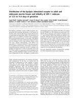
In Fig.2 the distribution of total intensity in phase plane (x,y) (it is similar in other
phase planes) is simulated for the collection of parameters given as: w0 = 1.0 × 10⁻⁶ m
dimension of particle a = 10 × 10−9 m, refractive index of particle n1 = 1.59, refractive of
surrounding medium n2 = 1.33, energy of every beam U = 0.1 × 10⁻⁶ J, laser wavelength
λ = 0.8 × 10⁻⁶ m, distance between two beam waist of every pair d = 20 × 10−6 m, duration
od pulse τ = 1×10⁻¹² s, radius of beam waist changes from w0 = 1.0×10⁻⁶ m (a), through
w0 = 1.5 × 10⁻⁶ m (b) to w0 = 2.0 × 10⁻⁶ m (c).
Fig. 2. Distribution of total intensity (W/m2 ) in phase plane (X,Y) with different
beam waist’s radius. (a) w0 = 1.0 × 10⁻⁶ m. (b) w0 = 1.5 × 10⁻⁶ m. (c) w0 =
2.0 × 10⁻⁶ m.
The intensity of laser pulsed beam is chosen at time, when it reaches a peak, it means
at t = 0. The simulations show that the total intensity focuses on five space regions: four
of them is around waist’s position, and the firth one around the cross position. The total
intensity redistributes with increasing of beam waist, its magnitude increases at cross
position, from 3.0 × 10¹⁰ W/m2 through 4.5 × 10¹⁰ W/m2 to 5.0 × 10¹⁰ W/m2 , and decreases
at waist positions.
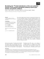
→
In Fig.3 the distribution of total optical force in X-axis (F x ) is simulated for above
collection of parameters. The simulations show that the total optical force acting on the
dielectric particle are divided into two parts whose directions are opposite to each other
and magnitudes are distributed as Gaussian functions of radial distance. With increasing
of beam waist the peak of force decreases from 5.0 × 10⁻⁶ N through 1.5 × 10⁻⁶ N to
6.0 × 10⁻⁷ N , meanwhile the stable region (a microsphere with radius from coordination
origin to position where optical force is maximum) increases.
248
H. Q. QUY, B. S. KHIEM, N. T. H. TRANG, M. V. LUU, C. V. LANH, D. H. SON
Fig. 3. Distribution of total optical force (N) in X-axis with different beam waist’s
radius: (a) w0 = 1.0 × 10⁻⁶ m; (b) w0 = 1.5 × 10⁻⁶ m; and (c) w0 = 2.0 × 10⁻⁶ m.
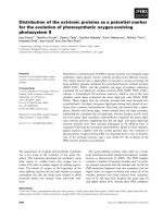
The distribution of the optical force is similar for other axis through the origin of
trap. This means that the stable region is a sphere, in whose surface there are maximum
centripetal forces. In every cross-section through the origin of trap, the distribution of the
optical force creates a potential cone, in which the particle always trends to fall down to
the bottom (see Fig.4).
Fig. 4. State of particle in the stable sphere.
DISTRIBUTUION OF THE LASER INTENSITY AND THE FORCE ACTING ON...
249
IV. CONCLUSION
In conclusion, we find that the total intensity and total optical forces in 3D-trap
using counter-propagating laser Gaussian beams are symmetrically distributed and depends on beam waist, firstly. But, the magnitude of optical force and the stable region
depend on many principle parameters as radius of particle, refractive index of particle and
of surrounding medium, distance between beam waists,...As shown in this article the total
optical force depends on the polarization vector, which plays an important role in process
for atom cooling. So it is necessary to discuss in the future. Moreover, from results for
3D-trap, some questions for 2D-trap can be answered easily.
REFERENCES
[1] C. L. Zhao, L. G. Wang, “Dynamic radiation force of a pulsed Gaussian beam acting on a Rayleigh
dielectric sphere”, Optical Society of America 32 (2007) 1393-1395.
[2] C. L. Zhao, L. G. Wang, X. H. Lu, “Radiation forces on a dielectric sphere produced by highly focused
hollow Gaussian beams”, Phys. Lett. A (2006) 502-506.
[3] Ho Quang Quy, Mai Van Luu, “Radiation Force Distribution of Optical Trapping by Two Counterpropagating CW Gaussian Beams Acting on Rayleigh Dielectric Sphere”, Comm. in Phys. 19 (2009)
174-180.
[4] Ho Quang Quy, Mai Van Luu, Hoang Dinh Hai, “Influence of Energy and Duration of Laser Pulses
on Stability of Dielectric Nanoparticles in Optical Trap”, Commun. in Phys. 20 (2010) 37-44.
[5] Ho Quang Quy, Mai Van Luu, Hoang Dinh Hai, Donan Zhuang, “Simulation of stability process of
dielectric nanoparticle in optical trap using counter-propagating pulsed laser Beams”, Chinese Optical
Letters 8 (2010) 332-334.
[6] A. A. Ambardekar, Y. Q. Li, “Optical levitation and manipulation of stuck particles with pulsed
optical tweers”, Opt. Lett. 30 (2005) 1797-1799.
Received 18-4-2011.