Low noise amplifier design and noise cancellation for wireless hearing aids
Bạn đang xem bản rút gọn của tài liệu. Xem và tải ngay bản đầy đủ của tài liệu tại đây (1.66 MB, 116 trang )
LOW NOISE AMPLIFIER DESIGN AND NOISE
CANCELLATION FOR WIRELESS HEARING AIDS
ZHANG LIANG
NATIONAL UNIVERSITY OF SINGAPORE
2005
LOW NOISE AMPLIFIER DESIGN AND NOISE
CANCELLATION FOR WIRELESS HEARING AIDS
ZHANG LIANG
A THESIS SUBMITTED
FOR THE DEGREE OF MASTER OF ENGINEERING
DEPARTMENT OF ELECTRICAL AND COMPUTER ENGINEERING
NATIONAL UNIVERSITY OF SINGAPORE
2005
Acknowledgements
I would like to thank my supervisors, Dr. Ram Singh Rana and A/Prof. Hari
Krishna Garg. They gave me opportunities to blossom my research ideas. Their research
attitudes and inspirations are impressed deeply on me. During the two years study, they
helped me open my mind and be an independent researcher. I learnt a lot from them not
only how to think about problems but also how to do the research work. I hope they are
proud of having me as research scholar as I am proud to have them as my supervisors.
Specifically thank to my colleague, TangBin who is pursuing his Graduate Program
in Bioengineering. I really appreciate many valuable discussions held with him.
Furthermore, I would like to thank the Institute of Microelectronics (IME) for providing
the scholarship in the past two years. This work has been supported by IME and NUS
(National University of Singapore). The infrastructure and the fabrication support
provided by IME are greatly acknowledged.
Finally, I thank my families for their never-ending support who had patience while I
was away from them during this research work.
i
Table of Contents
Acknowledgements
Summary
Table of Contents
List of Tables
List of Figures
Chapter 1
Introduction………………………………………………………………1
1.1
Introduction……………………………………………………………………1
1.2
Design Challenges of Hearing Aid Device ……………………………………10
1.3
Objective and Scope of Thesis ………………………………………………17
1.4
Organization of Thesis ………………………………………………………17
Chapter 2
Low Noise Amplifier Design and Optimization ………………………19
2.1
Introduction………………………………………………………………… 19
2.2
RF Models for LNA Design…………………………………………………19
2.3
LNA Design Topologies ………… …………………………………………24
2.4
Specification Freezing and Design Target ……………………………………26
2.5
Low Noise Amplifier Design………………………………… ………………28
2.6
LNA Simulation Results……………………………………………………35
2.7
Conclusions……………………………………………………………………38
Chapter 3 Low Noise Amplifier Measurement and Discussions…………………40
3.1
Introduction……………………………………………………………………40
3.2
LNA Chip Layout Development……………………………………………40
3.3
LNA PCB Layouts……………………………………………………………42
ii
3.4
LNA Measurement Setup and Testing ……………………………………47
3.5
LNA PCB Measurement Results and Discussion……………………………51
3.6
LNA Performance Comparison with Others Works…………………………57
3.7
Conclusions……………………………………………………………………58
Chapter 4
Noise Cancellation for Wireless Hearing Aid Devices…………………60
4.1 Introduction to Background Noise Cancellation ……………………………60
4.2
Behavior Model Development…………………………………………………67
4.3
Behavioral Simulation and Model Validation…………………………………71
4.4
Noise Cancellation Simulation in Wireless Hearing Aid……………………79
4.5
Conclusions……………………………………………………………………82
Chapter 5 Conclusions and Future Works…………………………………………84
5.1
New Development……………………………………………………………84
5.2
Main Conclusions……………………………………………………………84
5.3
Future Works…………………………………………………………………85
References
Appendices
A. LPLV LNA Design and Optimization Steps…………………………………92
B. Proof of Two-element Microphone Array Beamformer Limitation…………95
C. MATLAB Simulation Program for Noise Cancellation………………………98
D. Author’s Related Publications ………………………………………………103
iii
Summary
Wireless technology is one of the most promising approaches for future hearing
aids research. Compared to the conventional hearing aids, wireless hearing aids provide a
clearer voice, longer operation time, easy communication with other audio devices, and
so on. Although the advantages of the wireless hearing aids, noise cancellation and power
consumption are still the key issues in research, which require more efficient noise
cancellation method and lower power consumption circuit design.
Receiving the processed audio signal within the power budget of the wireless
hearing aid earpiece is one of the inherent design challenges. Low noise amplifier (LNA)
is the first stage to receive the signal, which is embedded in the earpiece of a wireless
hearing aid. There has been not much attempts to implement a CMOS receiver for the
earpiece of wireless hearing aid systems. As an attempt towards its CMOS
implementation, an integrated single-ended CMOS LNA with inductive degeneration at
the source is presented. The power consumption is the key issue to concern in this design.
Because the earpiece and the body unit for hearing aid device are separated within about
one meter, the noise figure and gain is not as important as power consumption. With the
small power consumption, the LNA should have good linearity also. According to the
normal hearing aid battery capacity, the total power consumption of an earpiece, where
receiver is the most power hungry block, should be as low as possible but below 3.0 mW
[1]. The recently reported 0.9 GHz CMOS receiver consumes 2.2 mW, out of which LNA
alone consumes 1.44 mW [2]. Reducing LNA power consumption will extend the battery
life. A single ended low voltage and low power LNA was implemented in CSM 0.18 µm
iv
CMOS technology. The LNA is powered at 1.0 V supply and drains only 0.95 mA. The
LNA provides a forward gain of 11.91 dB with a noise figure of only 2.41 dB operating
in the 0.9 GHz band. The IIP3 is 0.7 dBm and the P1dB is -12 dBm. The proposed design
also meets requirements on noise, linearity and gain for 0.9 GHz low power applications,
specifically suitable for CMOS wireless hearing aids.
Another consideration in this research work is about canceling the environmental
noise. Normally, an input to hearing aids is often associated with the environmental noise.
For instance, due to the environmental noise, a hearing-impaired person not only feels
severe hearing loss but also is unable to perceive desired speech from the noisy
environment. Thus, the noise cancellation is a primary concern, particularly for hearing
impaired. In this thesis, a modified two-element beamforming method for noise
cancellation is introduced, which helps reduce the surrounding environment noise. This
method needs to be verified before physical implementation. So, the behavior model for
this method is also presented, which shows a better noise cancellation performance. In
addition, the whole wireless hearing aid system is simulated using the proposed noise
canceling model. The simulation satisfies the proposed method.
v
Nomenclatures
ADC: Analog-to-Digital Converter
ADS: Advance Design System
BSIM: Berkeley Short-channel IGFET Model
BSIM3: third generation BSIM
CAD: Computer Aided Design
CIC: Completely In Canal hearing aid
CMOS: Complimentary Metal Oxide Semiconductor
CSM: Charted Semiconductor Manufacturer
DC: Direct Current
DAC: Digital-to-Analog Converter
DRC: Design Rule Check
DSP: Digital Signal Processing
DUT: Device Under Test
EDA: Electronics Design Automation
HA: Hearing Aid
IEEE: Institute of Electrical and Electronic Engineer
IIP3: Input-referred third-order Intercept Point
IME: Institute of Microelectronics, Singapore
ITC: In The Canal hearing aid
LNA: Low Noise Amplifier
LPLV: Low Power consumption Low Voltage
MIM: Metal Insulator Metal
vi
MOSFET: Metal-Oxide-Semiconductor Field Effect Transistor
NF: Noise Figure
NMOSFET: Negative Channel MOSFET
NQS: Non-Quasi-Static
PMOSFET: Positive Channel MOSFET
P1dB: 1 dB compressor Point
QPFSK: Quadrature Phase-Shift Keying
RF: Radio Frequency
SMA: SubMiniature version A
SNR: Signal to Noise Ratio
SPICE: Simulation Program for Integrated Circuits Emphasis
SPL: Sound Pressure Level
vii
List of Figures
Fig. 1.1 Some conventional hearing aids ………………………………………………4
Fig. 1.2
An analog hearing aid system…………………………………………………5
Fig. 1.3 A digital hearing aid system……………………………………………………6
Fig. 1.4 Typical wireless hearing aid principle …………………………………………8
Fig. 1.5
Typical wireless hearing aids system construction……………………………9
Fig. 1.6 Typical RF receiver architecture………………………………………………13
Fig. 1.7 Example for noise cancellation application situation in hearing aids design …16
Fig. 2.1
NMOSFET model for RF circuit design……………………………………21
Fig. 2.2 Layout of circular spiral inductors……………………………………………22
Fig. 2.3 Circular spiral inductor model…………………………………………………22
Fig. 2.4
Layout of MIM capacitors structure…………………………………………23
Fig. 2.5 MIM capacitor model…………………………………………………………24
Fig. 2.6 Different LNA topologies ……………………………………………………25
Fig. 2.7
LNA circuit schematic……………………………………… ………………29
Fig. 2.8
Noisy two ports network driven by noisy source……………………………31
Fig.2.9
Small equivalent circuit for CMOS LNA……………………………………33
Fig. 2.10 S-parameter input and output matching simulation results…………………36
Fig. 2.11 S-parameter noise figure simulation results…………………………………37
Fig. 2.12 S-parameter power gain simulation results…………………………………37
Fig. 3.1
LNA chip bounding diagram…………………………………………………42
Fig. 3.2
PCB description for LNA testing……………………………………………43
viii
Fig.3.3
Transmission line Z0 terminated with ZL……………………………………44
Fig. 3.4
Cross-section of symmetric coplanar waveguide with ground plane………45
Fig. 3.5
DC measurement setup………………………………………………………48
Fig. 3.6
S-parameters measurement setup……………………………………………48
Fig. 3.7
Noise figure measurement setup……………………………………………49
Fig. 3.8
Linearity measurement setup…………………………………………………50
Fig. 3.9
CMOS LNA noise figure measured results…………………………………51
Fig. 3.10 CMOS LNA gain measured results…………………………………………52
Fig. 3.11 CMOS LNA P1dB measured results…………………………………………52
Fig. 3.12 CMOS LNA input and output matching measured results……………………53
Fig. 3.13
LNA chip microphotograph…………………………………………………54
Fig. 4.1
Filter bank for noise cancellation……………………………………………60
Fig. 4.2
Two-element beamformer……………………………………………………63
Fig. 4.3
A two-element microphone array beamformer……………………………63
Fig. 4.4
Directivity pattern of two-element beamformer……………………………65
Fig. 4.5
A modified two-element beamformer………………………………………66
Fig. 4.6
Directivity pattern of modified two-element beamformer…………………67
Fig. 4.7
A typical system using noise cancellation in an audio device………………68
Fig. 4.8
Extended block diagram of single path beamforming………………………70
Fig.4.9
Directivity pattern of modified two-element beamformer with different
direction angle between noise and voice signal θ0 which is for constructing model……72
Fig. 4.10 Directivity pattern of modified two-element beamformer with different input
SNR………………………………………………………………………………………74
ix
Fig. 4.11
Directivity pattern of modified two-element beamformer with different
variances of signal σα and different variances of noise σβ………………………………75
Fig. 4.12
Directivity pattern of modified two-element beamformer with different center
frequency of signal and noise……………………………………………………………76
Fig. 4.13
Difference between input SNR and output SNR of modified two-element
beamformer for different frequency……………………………………………………77
Fig. 4.14
Difference between input SNR and output SNR of modified two-element
beamformer for different input SNR (noise frequency is at 1 kHz) …………………78
Fig. 4.15
Output SNR versus input SNR for typical wireless hearing aids……………81
Fig. 4.16 Output SNR improvement for typical wireless hearing aids ………………82
x
List of Tables
Table 1.1
Hearing aid battery capacity in the market …………………………………11
Table 2.1
Advantages and disadvantages of LNA topologies………………………26
Table 2.2 LNA specifications design target……………………………………………27
Table 2.3
Component values of LNA…………………………………………………34
Table 2.4
Proposed LNA simulation performance summary …………………………38
Table 3.1
Pin description of the LNA test chip………………………………………43
Table 3.2
Double-Sided FR-4 PCB parameters………………………………………46
Table 3.3
Component sizes in the LNA test PCB design……………………………47
Table 3.4
DC measurement equipment list……………………………………………47
Table 3.5
S-parameters measurement equipment list…………………………………48
Table 3.6
Noise figure measurement equipment list…………………………………49
Table 3.7
Linearity measurement equipment list………………………………………50
Table 3.8
LNA measurement summary………………………………………………55
Table 3.9 A comparison of recent LVLP CMOS LNA designs………………………59
xi
Chapter 1 Introduction
1.1
Introduction
Keeping in view the global population of hearing impaired people in the world,
there is a huge market demand on hearing aid devices. Thanks to the microelectronics
development, it attracts more and more the interest of industries attempting to exploit the
micro-technologies for hearing aids devices [3].
A hearing aid is an electronic, battery-operated device that amplifies and changes
sound to allow for improved communication. Hearing aids receive sound through a
microphone, which then converts the sound waves into electrical signals. The amplifier
increases the loudness of the signals and then sends the sound to the ear through a
speaker. Every conventional electrical hearing aid has mainly three parts [4] :
(1) A microphone used to collect the sound and convert into electrical impulses.
Thus, reproduces the rise and fall of pitch of the sound (high or low) and the intensity
(loudness measured in decibels).
(2) An amplifier, modulates the electrical impulses, makes sounds louder. It has an
integrated circuit comprising of several transistors or a combination of integrated circuits.
(3) A speaker (earphone) converts the amplified signal into sounds and feeds them
into the ear.
Hearing aids have been developed for a long time since the year 1800 [4], [5]. The
Greeks used shells and Romans had bronze funnels, but it was only in the 1800’s that the
first ear horns or trumpets were developed. In 1800’s London F C Rein company
1
established itself as the first company to manufacture hearing aids on a commercial basis.
In 1892 the first hearing aid, a carbon hearing aid, was produced at the Pilitzer Clinic in
Vienna. It consists of an earphone connected to a carbon microphone fastened onto a
battery box. Alexander Graham Bell is also credited as the first to build an earphone
which amplifies sound for the hearing impaired. In 1901 the first commercial aid was the
Akoulallion 1899, but this carbon ball invented in 1901 led to an increase in the quality
and reliability of electrical hearing aids. An electrical hearing aid was used by the English
Queen Alexandra for her coronation of 1902. In 1934, the first vacuum tube aid was
developed in England, consisting of a microphone, an earphone, an amplifier and two
batteries. Vacuum tube technology rapidly became the hearing aid standard. However,
the new vacuum aid requires two large batteries which usually last one day only. The
transistor was invented by Bell laboratories in 1947 and in 1953 transistor hearing
instruments were fabricated to make them smaller, cheaper and more effective. The
transistors allow behind-the-ear aids to develop. Other head worn aids are often attached
to hair with a clip. In 1970 hybrid hearing aids combined both digital and analog circuitry.
These were the first to include a digital chip and were a fraction of the size of previous
hearing aids. Leading up to the 70’s, behind the ear aids (BTE) almost fit behind the ear.
In-the-ear aids (ITE) became popular in the late 70’s, which are more reliable and smaller.
In the 1980’s, the first programmable hearing aids were developed. First digital hearing
aid circuits are similar to those in personal computers. Programmable aids allow user to
control hearing in different situation. In 1990’s the first automatic aids without volume
control were made available. Moreover, the first fully digital hearing aid came out in
1997. The first completely digital CIC was also announced around the same time. The
2
CIC hearing aids now are smaller than ever before allowing truly “invisible” hearing for
all. In 2001, with the RF technology and IC design development a kind of wireless
hearing aid was invented [1]. At present, the wireless hearing aids are the research focus
which would bring many advantages over the traditional hearing aids. The CMOS
technology seems the most promising to provide high performance.
Hearing aid manufacturing is a highly technical and delicate task. Most of the
hearing impaired persons’ hearing losses are different from each other’s hearing loss, so
each hearing instrument has to be customized to match the user's exact needs. The
elements which go into making a hearing aid should not be compared to a pair of
spectacles, which have mass-produced frames and lenses, but are actually closer to that of
a sophisticated piece of specialist hi-fi equipment. As every customer's hearing loss is
unique, so every hearing aid is different. The type of hearing aid best suited to a customer
depends largely on their type of hearing loss, in addition to the physical and cosmetic
considerations [6]. In Fig. 1.1 a few sample of the range of styles and sizes of hearing
instrument available in the market are depicted [7].
3
Fig. 1.1
Some conventional hearing aids
Behind the ear hearing aids (BTE) are usually cheaper, easier to adjust than other
devices. It is fairly visible and usually more powerful, thus fewest number of problems
with wax or infections. Completely in the canal hearing aid (CIC) cannot be seen and
require tight fit. It is hard to adjust and remove. CIC aid is so small that it is invisible.
However, the battery capacity is limited, so the user needs to change the battery more
frequently. Behind the ear hearing aids are bigger in size than CIC aids. Hence more
circuits can be built in with more functions, such as clearer voice. In the ear hearing aid
(ITE) is less visible, harder to put in and adjust compared to the CIC aid. In the canal
4
hearing aid (ITC) is even less visible and consumes less power than ITE. As a result,
hearing-impaired patients with tremor or poor eyesight are not good candidates for
ITC/CIC aids. Cochlear implant hearing aids are more advanced, mostly recommended to
patients with profound loss/deaf [7]. First, sound is picked up by a directional
microphone and sent from the microphone to the speech processor. Then the speech
processor analyzes and digitizes the sound into coded signals. Third, coded signals are
sent to the transmitter via radio frequency. The transmitter sends the code across the skin
to the internal implant. Fourth, the internal implant converts the code to electrical
signals. The signals are sent to the electrodes to stimulate the corresponding hearing
nerve fibers. Finally, the signals are recognized as sounds by the brain, thus produce a
hearing sense.
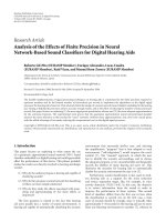
Fig. 1.2 An analog hearing aid system
For simplicity, among the above mentioned hearing aids, from circuit point of view
hearing aids can be categorized mainly of two kinds: (i) the conventional hearing aids and
(ii) wireless hearing aids. Wireless hearing aids using wireless technology are under
investigations [1]. From the circuit operation and signal processing point of view, the
conventional hearing aids are generally of two types: (i) analog hearing aid (Fig. 1.2) and
(ii) digital hearing aid (Fig. 1.3) [5], [7]. Analogue hearing aids use microphone to
convert sounds into an electric signal which is modified in a miniature amplifier and
converted back into sound by a receiver. That sound passes into the ear and is heard by
5
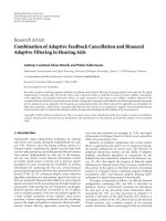
the patient. After 1996, with the rapid growth in digital communications, the first digital
hearing aid was fabricated. The digital hearing aid uses the microphone to get the
electrical signal. Then after A/D conversion, the digital signal processing (DSP) is
performed to get rid of the noise and modulate the signal. Finally, the digital signal is
converted to analog signal which is heard by the user. Hearing aids with digital
technology contain a very advanced degree of signal processing that can provide better
accuracy, sound quality, perception of loudness and environmental noise reduction [5],
[8]. At the same time, digital hearing aids can have many separate amplifier channels.
Most digital models are programmable using personal computers and can offer a high
degree of flexibility and precision. Moreover, the digital hearing aid, which is so small as
to be practically invisible out of canal, could be compared to a contact lens.
Fig. 1.3 A digital hearing aid system
Because of the advantages of the digital hearing aid, many researchers focus on the
digital hearing aid. The major concerns in the hearing aid design are noise and echo
cancellation by DSP and the whole system power consumption budget. However, taking
into account the limited size and battery supply in hearing aid devices, putting DSP chip
in the earpieces perhaps is intuitively not the best choice. For traditional hearing aids, the
battery capacity is limited, such as one kind of 600 mAh battery in the market [9],
because of the small size of hearing aids. It is difficult to build complex circuits for the
hearing aids, because of the limited power supply, especially for the CIC. For example,
some good noise cancellation performance method can not be built in the hearing aid
6
(HA), which needs more circuits to be implemented. Usually, conventional hearing aids
use the filter banks to cancel the noise, so the noise cancellation performance is limited.
To solve this problem, some manufactures use bipolar technology in their hearing
products, because the bipolar technology consumes less power to get the similar
performance compared to the CMOS technology. However, the hearing aids built with
bipolar technology are more expensive than those with the CMOS technology.
The size of the hearing aid is small, such as CIC, so it is not practical to design a
hearing aid in only one part with the trade off in size, power consumption, and efficiency.
It faces challenges to improve the hearing aids performances further.
The integrated circuits design has been scaled down to deep submicron (DSM)
technology. Analog, digital, mixed signals and radio frequency signals processing circuits
can be built into one chip. Digital signal processing methods are more advanced than
before, better noise canceling circuits can be implemented in a DSP chip. Considering
recent evolutions, the wireless hearing aids having multi-microphones, analog, digital and
mixed signals and radio frequency signals processing circuits, DSP and programmable
unit seem to be promising to provide enhanced performance [1], [10].
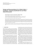
A typical wireless hearing aid scheme is shown in Fig. 1.4. It has a body unit and an
earpiece [1]. The earpiece communicates with the body unit by a RF link. The earpiece
receives the audio signal and converts it into an electrical signal. After A/D conversion,
the signal processing is done in the body unit and transmits back into the earpiece using
RF link. The earpiece converts the RF signal into audio signal and feeds it into the
patient’s ear. This kind of wireless hearing aid has several characteristics. It gives better
noise cancellation, easy trade off in hearing aid earpiece power consumption and size etc.
7
Fig. 1.4 Typical wireless hearing aid principle
Based on the concept of RF link as shown in Fig. 1.5 [1], a typical wireless hearing
aid can be configured as shown in Fig. 1.5. In this architecture, the wireless hearing aid
has two separate parts, a body unit and an earpiece with RF wireless links connecting
between them. The voice sound is received by the microphones in the earpiece. In order
to get a clearer voice, only one microphone is not enough [5]. So, in the wireless hearing
aids, there are two omni-directional microphones built in the body unit, which not only
provide a good noise cancellation performance, but also help the users locate the sound.
The microphone outputs are amplified to feed forward into the following AD converter.
After AD conversion, the data are transmitted into a RF receiver in the body unit. The
DSP block following the RF receiver lies in the body unit and functions to eliminate
unwanted surrounding noise, reverberations and echo. Various DSP algorithms are
implanted to realize complex functions [11], [12]. The noise cancellation output is
transmitted between earpiece and body unit via RF wireless link. Modulation methods are
optimized for a tradeoff between size, complexity and power. After the RF receiver
receives the RF signal from RF transmitter in the body unit, the signal is down converted
8
to low frequency signal. Then the digital signal is converted to analog signal by D/A
converter to drive the earpiece speaker.
Fig. 1.5 Typical wireless hearing aids system construction
Some characteristics of a wireless hearing aid, compared to the conventional
hearing aids, as discussed below:
(1) Wireless hearing aids primarily have two parts, body unit and earpiece,
connected by a RF link. The body unit size is bigger than conventional hearing aid size.
The bigger battery with higher capacity is used in the body unit. The power hungry
circuits for hearing aids can be built in body unit. As a result, the earpiece can be built
with less power consumption circuits and of the smaller size.
(2) Better noise cancellation method is implemented in DSP part in the body unit
for clear voice. There are several good noise cancellation performance methods based on
adaptive signal processing, which are built in the DSP block. Moreover, two microphone
inputs and binaural configuration also help noise cancellation and sound localization.
(3) In order to be compatible with other audio device, these functions can be
realized in DSP block inside body unit. As is a trend to be all-in-one, the features of the
body unit can be embedded with other audio devices, such as mobile phone, MP3 player,
FM receiver and other handheld audio devices.
9
(4) HA circuit noise is one of the most stringent problems for the HA users, if the
circuit noise is so large that makes the useful signal distortion. It is possible to design
more compensation circuits for less noise in body unit, because of more power capacity
and larger size of body unit.
Keeping above in view, wireless hearing aids seem quite promising, which are
currently under research and investigations.
1.2 Design Challenges of Hearing Aid Device
For a long time, hearing impairment has been an inevitable severe problem in the
medical community. However with technological evolutions, attempts have been made to
provide hearing aids. With the increase of IC technology development, currently
available hearing aid devices, such as analog hearing aids, though help the patients up to
certain extent, have the severe problems related with noise and echo. They do not satisfy
users’ need. With time, technology has been further advanced and it has opened a wider
window to overcome such problems. More and more researchers [1], [3] show their
interests in the study of advanced hearing aid devices which give more benefit to the
hearing impaired. Many of them focused on the issue of digital signal processing (DSP)
method for noise cancellation, speech quality improvement, ultra low power consumption
and lower price, etc. However, there are a number of design challenges to bring the
technology to the end user. It includes issues related with minimum power consumption,
noise cancellation, size and portability, etc.
10
1.2.1 Size and Power Consumption
A hearing aid system invisible to other people like CIC or ITC hearing device is
more acceptable to the impaired nowadays. However, the limited size of hearing devices
is not able to hold current complex functions, which needs more complicated circuits and
power consumption.
The problem is how to realize a tiny hearing aid with complex function. While
highly integrated circuit is needed to realize complex functions, separating redundant
components from ear-piece to a body unit can be a choice [10].
Battery life is a crucial characteristic of hearing aid devices. Worn by the patients
throughout the day, hearing devices are expected to maintain a longer working life. Some
researches [13] focus on developing long-lasting batteries which are out of the scope of
this thesis. Another way is using rechargeable battery that is recharged when it has no
power. In the market, there are different kinds of batteries for hearing aids.
Unfortunately, the power capacity of battery for hearing aid is limited, even for BTE
hearing aids. In Table 1.1, some hearing aids battery capacities are shown [9]. At the one
side, investigations are needed to enhance the battery capacity, at the other side, circuit
design researches are focused on reducing power consumption of the hearing aid systems.
Table 1.1 Hearing aid battery capacity in the market
Battery model number
H.A. type
Capacity / mAH
A675
BTE
600
A13
BTE/ITE
260
A312
ITE/ITC
150
A10
ITC/CIC
80
A675P
Cochlear
520
The present hearing aids are built using microchip and other electronic components.
Obviously, the microchip power consumption should be reduced. In the conventional
11
hearing aids, especially digital hearing aids, noise cancellation method is implemented in
the chip. Since the complexity of noise cancellation algorithm should be increased for
improved noise cancellation performance, so as the power consumption. With the
development of semiconductor technology, especially submicron technology, the circuits
can be built with much less power consumption to realize same function. To further
reduce the circuit power consumption, the number of off-chip components should be
reduced. The system power cost is greatly reduced to a much lower level by integrating
components to one silicon chip. Current technique on semiconductor has been used in
hearing aid device to reduce both its size and power consumption. However, even with
these methods to reduce circuit power consumption, it is still difficult to get a better noise
cancellation in with limited power budget.
Many researchers have shown their interests in monolithic hearing aid design with
technology of 0.6 µm CMOS [3] and 0.8 µm BiCMOS [1] in the past 3 years. However,
these have inherent limitations. Normally, the price for implementing circuits in
BiCMOS technology is higher than implementing circuits in CMOS technology. Hence,
wireless hearing aid implemented in CMOS technology may be a more economic
solution.
Digital circuits are designed in CMOS technology, such as DSP chip, because of the
higher speed and lower power consumption. At present, the CMOS technology has
already reached the 0.18 µm. In some situations, the analog circuit and RF circuit can be
implemented in CMOS technology with the similar performance compared to the one
with bipolar technology. In the wireless hearing aid design, it includes not only digital
circuit part but also analog circuit, RF circuit part. So when the chip, which includes
12