tài liệu biến tần CUTES CT2000F
Bạn đang xem bản rút gọn của tài liệu. Xem và tải ngay bản đầy đủ của tài liệu tại đây (1.06 MB, 136 trang )
C.TY TNHH TỰ ĐỘNG HÓA VIỆT TRUNG
02413.281.181-0989.984.666
Cutes Corporation
CT-2000F Series
AC MOTOR DRIVER
Instruction
Head Office : 2-22, Nan Yuan Road, Chung Li City, Taiwan
TEL: 886 3 4612333 or 886 3 4526161 ext. 275, 266, 512
FAX: 886 3 4526227 or 886 3 4511347
E-mail:
URL: www.cutes.com.tw
Website:www.viet-trung.com.vn
Đ/c:194-Nguyễn Trãi-Võ Cường-TP.Bắc Ninh 1
C.TY TNHH TỰ ĐỘNG HÓA VIỆT TRUNG
bsite:www.viet-trung.com.vn
02413.281.181-0989.984.666
Đ/c:194-Nguyễn Trãi-Võ Cường-TP.Bắc Ninh 2
C.TY TNHH TỰ ĐỘNG HÓA VIỆT TRUNG
02413.281.181-0989.984.666
Introduction / Table of Contents
Introduction
Thank you for choosing the CT-2000 inverter unit, this inverter unit is suitable for operating
squirrel cage induction motors. Please read this instruction manual carefully before actual
usage in order to ensure proper operation and suit your needs.
Table of Contents
1. Inspection upon receiving…………………………………………………. 4
2. Installation and Storage…………………………………………………… 4
A. Installation and………………………………………………………….. 4
B. Storage…………………………………………………………………… 4
3. Application notes…………………………………………………………… 5
4. Block diagram and Wiring ………………………………………………… 5
A. Wiring of main and control circuit …………………………………… 5
B. Signal circuit……………………………………………………………. 5
C. Connecting the power supply and the AC motor…………………… 6
D. R.S.T. for Power source reactor……………………………………… 7
E. Standard external connection diagram……………………………… 8
F. Control circuit specification………………………………………….... 9
G. Terminal specifications……………………………………………….. 10
5. Operation Test……………………………………………………………… 11
6. Function Setup and Specification.……………………………………….. 13
A. Keypad operation………………………………………………………. 13
B. Display specification…………………………………………………… 14
C. Keypad specification…………………………………………………… 14
D. Function Code………………………………………………………….. 15
7. Description of alarm display indications ………………………………… 45
8. Troubleshooting……………………………………………………………. 47
9. Maintenance and Inspection……………………………………………… 49
10. Standard Specification…………………………………………………….. 50
A. 200V series……………………………………………………………… 50
B. 400V series……………………………………………………………… 50
C. Standard specification………………………………………………….. 51
D. Outline dimension………………………………………………………. 52
11. Function code Table……..………………………………………………. 53
12. Modbus Address of Display Data….…………………………………… 60
13. Series Communication User Manual..…………………………………. 62
A. The physical link………………………………………………………… 62
B. Data structure in communication……………………………………… 63
Website:www.viet-trung.com.vn
Đ/c:194-Nguyễn Trãi-Võ Cường-TP.Bắc Ninh 3
C.TY TNHH TỰ ĐỘNG HÓA VIỆT TRUNG
02413.281.181-0989.984.666
C. Function code in Modbus……………………………………………… 66
D. Error check generation………………………………………………… 67
E. Group & global broadcasting…………………………………………. 69
- 3 -
Website:www.viet-trung.com.vn
Đ/c:194-Nguyễn Trãi-Võ Cường-TP.Bắc Ninh 4
C.TY TNHH TỰ ĐỘNG HÓA VIỆT TRUNG
02413.281.181-0989.984.666
Inspection upon receiving / Installation and storage
1. Inspection upon receiving
A. Check that the model, the capacity and power voltage specifications are as
ordered.
B. Check that no damage has occurred during transportation.
C. Check that none of the internal parts have been damaged or have fallen off.
D. Check that none of the connectors have been damaged or have fallen off.
E. Check that there is no loosening of the terminals or screws of each of the parts.
2. Installation and Storage
A. Storage:
If the equipment is not to be installed immediately, it should be stored in a clean and
dry location at ambient temperatures from 20℃to 55℃. The surrounding air must
be free of corrosive contaminants.
B. Installation place:
Places where the peripheral temperature is from -10℃to 40℃, and where the
relative humidity is 90% or less. Avoid installing at places where there is dust, iron
particles, corrosive gas, water spray, direct sunlight or too much vibration. And
places where has good ventilation.
10cm
min.
10cm
min.
10cm
min.
10cm
min.
Website:www.viet-trung.com.vn
Đ/c:194-Nguyễn Trãi-Võ Cường-TP.Bắc Ninh 5
C.TY TNHH TỰ ĐỘNG HÓA VIỆT TRUNG
02413.281.181-0989.984.666
- 4 -
Website:www.viet-trung.com.vn
Đ/c:194-Nguyễn Trãi-Võ Cường-TP.Bắc Ninh 6
C.TY TNHH TỰ ĐỘNG HÓA VIỆT TRUNG
02413.281.181-0989.984.666
Block diagram, wiring
3. Application notes
A. Concerning the inverter unit:
(1) Do not fit capacitors to the output side of the inverter in order to improve the
power ratio.
(2) In case of fitting MC between inverter and motor to control motor operation,
then the capacity of inverter must be 6 times the capacity of motor.
(3) Run a motor that is within the capacity of the inverter unit, light load current and
no-load current will cause the motor to develop ripple current.
(4) This unit is provided with a current limiting function. The starting torque is
assumed to be from 80% to 100%.
B. Concerning the AC motor
(1) When general-purpose motors are operated at low speeds, there is a reduced
cooling effect, please apply the special purpose motor.
(2) Operation at frequencies exceeding 60 Hz requires caution, as there is the
danger of the mechanical strength failure of the motor.
(3) When motors with brakes are being operated, the power for the brake and
inverter should be taken from the same power supply and the brake operation
must be in phase when the unit is started and stopped.
4. Block diagram, Wiring
A. Wiring of main and control circuit
Wire according to the standard connection diagram. On using the external
sequence control, please use small signal relay or double terminal relay to avoid
relay terminal malfunction.
B. Signal circuit
The signal circuit uses either shielded pairs or twisted pairs, should be wired either
using a wiring duct separated from that for the power circuit, or with the wiring
conduit isolated as much as possible.
Website:www.viet-trung.com.vn
Đ/c:194-Nguyễn Trãi-Võ Cường-TP.Bắc Ninh 7
C.TY TNHH TỰ ĐỘNG HÓA VIỆT TRUNG
02413.281.181-0989.984.666
- 5 -
Website:www.viet-trung.com.vn
Đ/c:194-Nguyễn Trãi-Võ Cường-TP.Bắc Ninh 8
C.TY TNHH TỰ ĐỘNG HÓA VIỆT TRUNG
02413.281.181-0989.984.666
Block diagram, wiring
C. Connecting the power supply and the AC motor
Connect the main circuit, by wiring according to the main circuit terminal connection
diagram. Care is required not to make a mistake when connecting the input and
output terminals, lest it will cause inverter damage. Specifications of main circuit
path and NFB are as follow:
Voltage (V)
220
380
|
440
Website:www.viet-trung.com.vn
Model
NFB (A)
CT-2002-A75
CT-2002-1A5
CT-2002-2A2
CT-2002-3A7
CT-2002-5A5
CT-2002-7A5
CT-2002-011
CT-2002-015
CT-2002-022
CT-2002-030
CT-2002-037
CT-2002-045
CT-2002-055
CT-2002-075
CT-2002-093
CT-2004-A75
CT-2004-1A5
CT-2004-2A2
CT-2004-3A7
CT-2004-5A5
CT-2004-7A5
CT-2004-011
CT-2004-015
CT-2004-022
CT-2004-030
CT-2004-037
CT-2004-045
CT-2004-055
CT-2004-075
CT-2004-093
CT-2004-112
6A
10A
15A
20A
30A
40A
60A
80A
120A
150A
200A
250A
300A
400A
500A
5A
5A
7.5A
10A
15A
20A
30A
40A
60A
80A
100A
120A
150A
200A
250A
300A
Wire size for
circuit (mm2)
2~5.5
2~5.5
3.5~5.5
5.5
5.5~8
5.5~8
22
30
38
38~100
38~100
60~100
100
100~200
100~200
2~5.5
2~5.5
2~5.5
3.5~5.5
3.5~5.5
5.5
8~14
8~14
22
22
30
50
38~100
38~100
60~100
100
Đ/c:194-Nguyễn Trãi-Võ Cường-TP.Bắc Ninh 9
C.TY TNHH TỰ ĐỘNG HÓA VIỆT TRUNG
02413.281.181-0989.984.666
- 6 -
Website:www.viet-trung.com.vn
Đ/c:194-Nguyễn Trãi-Võ Cường-TP.Bắc Ninh 10
C.TY TNHH TỰ ĐỘNG HÓA VIỆT TRUNG
02413.281.181-0989.984.666
Block diagram, wiring
D. Instantaneous current and to improve power ratio, it should be fitted the A.C.L. to
R.S.T. input side under the following circumstance:
a. Where power supply capacity is larger than 500 KVA.
b. Using thyrister, phase advance capacitor etc. from the same power supply.
A.C.L. Specifications table:
Voltage (V)
Model
CT-2002-A75
CT-2002-1A5
CT-2002-2A2
CT-2002-3A7
CT-2002-5A5
CT-2002-7A5
220
CT-2002-011
CT-2002-015
CT-2002-022
CT-2002-030
CT-2002-037
CT-2002-045
CT-2002-055
CT-2002-075
CT-2002-093
CT-2004-A75
CT-2004-1A5
CT-2004-2A2
CT-2004-3A7
CT-2004-5A5
CT-2004-7A5
380
CT-2004-011
|
CT-2004-015
440
CT-2004-022
CT-2004-030
CT-2004-037
CT-2004-045
CT-2004-055
CT-2004-075
CT-2004-093
CT-2004-112
Current (Ar.m.s)
6A
10A
15A
20A
30A
40A
60A
80A
120A
150A
200A
250A
300A
400A
500A
5A
5A
7.5A
10A
15A
20A
30A
40A
60A
80A
100A
120A
150A
200A
250A
300
Induction Value
1.8mH
1.1mH
0.71mH
0.53mH
0.35mH
0.26mH
0.18mH
0.13mH
0.09mH
70uH
50uH
44uH
35uH
27uH
21uH
4.2mH
4.2mH
3.6mH
2.2mH
1.42mH
1.0mH
0.7mH
0.53mH
0.36mH
0.26mH
0.21mH
0.18mH
0.14mH
0.11mH
0.10mH
70uH
Notes: The A.C.L. for 220V and 380V/460V have different induction values, please does
not mix up.
Website:www.viet-trung.com.vn
Đ/c:194-Nguyễn Trãi-Võ Cường-TP.Bắc Ninh 11
C.TY TNHH TỰ ĐỘNG HÓA VIỆT TRUNG
02413.281.181-0989.984.666
- 7 -
Website:www.viet-trung.com.vn
Đ/c:194-Nguyễn Trãi-Võ Cường-TP.Bắc Ninh 12
C.TY TNHH TỰ ĐỘNG HÓA VIỆT TRUNG
02413.281.181-0989.984.666
Block diagram, wiring
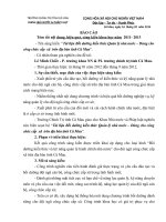
E. Standard External Connection Diagram
(Note: While external is required for DBR, disconnect inter DBR first
TM
DBR
P
PR
Adaptor
ACL
N
Convertor
3-phase power
200V/50Hz
200~230V/50,60Hz
R
U
S
V
400V/50Hz
400~460V/50,60Hz
T
W
IM
E
Voltage detect
Current detect
Ext. Operation
controller
5KΩ 1/2W
Ext. Operation
controller
5KΩ 1/2W
Braking
control
10V
IN3
CC
interface
10V
CPU
VOUT
CC
IN2
Analog output
terminal
Power control
CC
External signal 4〜20mA
IN1
Operational
panel
0V
Terminal 1
DI1
Terminal 2
DI2
C1
Terminal 3
DI3
NO1
Terminal 4
DI4
NC1
Terminal 5
DI5
Terminal 6
DI6
Reverse operation
Forward operation
Twisted or shield wires
C2
NO2
RR
NC2
FR
COM
Multi-function Relay
output terminal 1
Multi-function Relay
output terminal 2
RJ45
REMOTE
A+ A- B+ B-
RS422/485 Series communication interface terminal
Website:www.viet-trung.com.vn
Đ/c:194-Nguyễn Trãi-Võ Cường-TP.Bắc Ninh 13
C.TY TNHH TỰ ĐỘNG HÓA VIỆT TRUNG
02413.281.181-0989.984.666
- 8 -
Website:www.viet-trung.com.vn
Đ/c:194-Nguyễn Trãi-Võ Cường-TP.Bắc Ninh 14
C.TY TNHH TỰ ĐỘNG HÓA VIỆT TRUNG
02413.281.181-0989.984.666
Block diagram, wiring
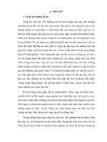
F. Control circuit
C1
NO1 NC1
No.1
Multifunctional
relay output
terminal
Vout
IN1
IN2
C2
NO2 NC2
No.2
Multifunctional
relay output
terminal
IN3
VC
CC
1/2W
5K ohm
4-20mA
Current
0-10V Set
DC
Voltage
Output
Accessory
Voltage
Set
1/2W
5K ohm
Main Voltage Set
COM
AC2
DC2
3DF
JOG
2DF
RST
1
2
3
4
5
6
Multifunctional
input
terminal
Website:www.viet-trung.com.vn
Multifunctional
input
terminal
Multifunctional
input
terminal
RR
FR
COM
Reverse Forward
operation operation
Đ/c:194-Nguyễn Trãi-Võ Cường-TP.Bắc Ninh 15
C.TY TNHH TỰ ĐỘNG HÓA VIỆT TRUNG
02413.281.181-0989.984.666
- 9 -
Website:www.viet-trung.com.vn
Đ/c:194-Nguyễn Trãi-Võ Cường-TP.Bắc Ninh 16
C.TY TNHH TỰ ĐỘNG HÓA VIỆT TRUNG
02413.281.181-0989.984.666
Block diagram, wiring
G. Terminal Specifications
Main
R.S.T AC power input terminal
Circuit
U.V.W Inverter output terminal
E
Ground terminal
P.PR Brake resistor connecting
terminal
Control
VC Power speed output setting
Terminal IN1 Current speed input setting
(1)
IN2 Voltage speed input setting
IN3 Voltage speed input setting
VOUT Operation (Frequency
/Current) output indication
CC Common input control
terminal
Control COM Sequence control common
Terminal
terminal
(2)
FR Forward operation input
terminal
RR Reverse operation input
terminal
DI1 2nd acceleration input
terminal (AC2)
DI2 2nd deceleration input
terminal (DC2)
DI3 3rd speed input terminal
(3DF)
DI4 Jogging operation or 5th
speed (JOG/5DF)
DI5 2nd speed input terminal
(2DF)
DI6 Free-run operation or alarm
reset (MBS/RST)
A+,AC1,
B+,B- SG
NC1,
NO1,
C2,
NC2,
NO2
Website:www.viet-trung.com.vn
3∮AC power 200-230V/50,60Hz
380-460V/50,60Hz
3-phase induction motor
Ground terminal of inverter chassis
Connected proper brake resistor
according to rated ampere
DC 10V
DC 4-20mA, CD01=2 or 5
DC 0-10V/5KΩVR, CD01=1,4,3 or 6
DC 0-10V/5KΩVR, CD01=3 or 6
Analog Output 0~10V DC,
Frequency/Current set by CD54
Ground terminal for speed setting
Ground terminal for sequence control
Forward operation by FR-COM shorted
Reverse operation by RR-COM shorted
Select 2nd acceleration time mode by
shorting 1-COM, set CD10
Select 2nd deceleration time mode by
shorting 2-COM, set CD11
Select 3rd operation speed by shorting
3-COM, frequency is set by CD13
Shorting 4-COM, JOG/5DF is set by
CD59
Select 2nd operation speed by shorting
5-COM, frequency is by CD12
Shorting 6-COM, MBS/RST is set by
CD59
Control output terminal
NO
NC
C1
Đ/c:194-Nguyễn Trãi-Võ Cường-TP.Bắc Ninh 17
C.TY TNHH TỰ ĐỘNG HÓA VIỆT TRUNG
Serial
communication
terminal
02413.281.181-0989.984.666
Multifunctional
relay
output
terminal
Connector
capacity
AC
220V,
0.1A
While normal
C-X
closed
and
NC-X
Closed
While operating C-X
open and NO-X
closed
Functions of C1, NC1,
NO1 are set by
CD47
Functions of C2, NC2,
NO2 are set by
CD48
Refer to Serial
Communications User
Manual.
SG is 0 volt terminal of
the digital signal.
- 10 -
Website:www.viet-trung.com.vn
Đ/c:194-Nguyễn Trãi-Võ Cường-TP.Bắc Ninh 18
C.TY TNHH TỰ ĐỘNG HÓA VIỆT TRUNG
02413.281.181-0989.984.666
Operation Test
5. Operational Test
A. Check before test
Please check the following:
(1) Is wiring correct? Check especially the input and output terminals.
(2) Is there a short-circuit or ground connection on external wiring?
(3) Make sure there is no loosening of screws.
(4) Check external sequence control circuit.
(5) Check voltage of power supply.
B. Operation Method
CT-2000 series inverter unit has both operator panel and external operation methods.
(1) Operator panel
M
PANEL INPUT
CT2000
FN-800
(2) External signal operation
MCB
M
SWITCH CONTROL
CT2000
FN-800
Website:www.viet-trung.com.vn
Đ/c:194-Nguyễn Trãi-Võ Cường-TP.Bắc Ninh 19
C.TY TNHH TỰ ĐỘNG HÓA VIỆT TRUNG
02413.281.181-0989.984.666
- 11 -
Website:www.viet-trung.com.vn
Đ/c:194-Nguyễn Trãi-Võ Cường-TP.Bắc Ninh 20
C.TY TNHH TỰ ĐỘNG HÓA VIỆT TRUNG
02413.281.181-0989.984.666
Operational Test
C. Operational test
Test according to the following procedure and be aware of indications.
(1) Basic operational test
-Operational procedure
I. Connect power supply
II. Monitor glittering indicates frequency
III. Press either FWD or REV key, motor starts running. It will stop accelerating
after reaching set frequency
IV. After pressing STOP key, motor stops and indicating frequency steps down.
The set frequency starts glittering after the motor stops.
V. Repeat procedures III and IV to test forward and reverse operations.
-Operation monitor display
I. STOP display, with reciprocal glittering indicated HZ LED and factory setting
10.00HZ.
II. Hz display, with FWD (or REV) LED lighted up steadily; indication goes up
according to frequency until reaching value 10.00 Hz
III. Indication goes down according to operation frequency, and returns to
situation ” I ” after stop
(2) Frequency change test
- Operational procedure
I. Exercise the above operation test procedures I, II, III
II.
Adjust VR on the panel to change frequency command
III. Repeat procedures II to increase or decrease frequency
-Operation monitor display
I. The same as the above basic test of I, II
II. Monitor display indicates the current new setting value
Note:
1. Is motor operation direction correct? (Changing any two of U.V.W output
terminals to change motor operation direction)
2. Is there any noise or vibration on motor?
3. Is it run smoothly during acceleration and deceleration?
4. Is there any power failure?
Website:www.viet-trung.com.vn
Đ/c:194-Nguyễn Trãi-Võ Cường-TP.Bắc Ninh 21
C.TY TNHH TỰ ĐỘNG HÓA VIỆT TRUNG
02413.281.181-0989.984.666
- 12 -
Website:www.viet-trung.com.vn
Đ/c:194-Nguyễn Trãi-Võ Cường-TP.Bắc Ninh 22
C.TY TNHH TỰ ĐỘNG HÓA VIỆT TRUNG
02413.281.181-0989.984.666
Adjust and Function Specification
6. Adjust and Function Specification
A. Keypad operation
Operator panel parts
names and functions
READY
7-segement
monitor
Displays that the panel is
ready to accept key input
1.Displays frequency
Cd02=0
Displays current Cd02=1
Displays RPM NO2=2
Displays various readings
see Cd02
2. After indicates alarm,
ignore Cd02, directly
displays
failure status
Operation monitor
display
Monitor mode
display
Displays monitor status
Ten-key pad
Data input key
Cutes Corporation
。READY
。HZ
。A
。ALARM
Displays forward/reverse/stop status
Operation instruction
keys
Control from keyboard
External control operation, stop
mode by set Cd04=1
STOP key
1. Stops inverter operation
2. Resets function
3. Resets alarm indication
FWD
REV
STOP
1
PROG
READ
SET
1
7
8
9
4
5
6
1
2
3
0
.
Step keys
1. To change frequency
2. Select function items
Function setting keys
These three keys offer selecting
read or setting value of function
Website:www.viet-trung.com.vn
Đ/c:194-Nguyễn Trãi-Võ Cường-TP.Bắc Ninh 23
C.TY TNHH TỰ ĐỘNG HÓA VIỆT TRUNG
02413.281.181-0989.984.666
- 13 -
Website:www.viet-trung.com.vn
Đ/c:194-Nguyễn Trãi-Võ Cường-TP.Bắc Ninh 24
C.TY TNHH TỰ ĐỘNG HÓA VIỆT TRUNG
02413.281.181-0989.984.666
Adjust and Function Specification
B. Display specification
LED
Display specification
READY
READY LED means the Keyboard working normally.
HZ
Hz LED means of recent revolution frequency.
A
A LED means of recent revolution current.
FWD
FWD LED means motor operate at forward direction.
REV
REV LED means motor operate at reverse direction.
STOP
STOP LED means motor operate at stop.
C. Keyboard specification
Bottom
Function
MOTOR RUN
FWD
Bottom specification
Push keypad to control forward of motor, and screen
display main display content (Cd02 setting).
MOTOR RUN
Push keypad to control reverse of motor, and screen
display main display content (Cd02 setting).
STOP
Stop motor revolution when push STOP key, and on the
mean time screen flashing with commanding
instruction.
While failure occurred, press STOP key to re-start
inverter and save failure in failure memory.
REV
STOP
RESET
SELECT
FUNCTION
PROG
In display mode, press PROG key and screen shows
Cd00 (General parameter input area). Press
PROG/SET key again and screen shows CE-00 (failure
and engineering mode). If pressed PROG/SET key
now, screen would return to display mode.
SET
READ
Website:www.viet-trung.com.vn
Đ/c:194-Nguyễn Trãi-Võ Cường-TP.Bắc Ninh 25