tài liệu biến tần EURA f1000g
Bạn đang xem bản rút gọn của tài liệu. Xem và tải ngay bản đầy đủ của tài liệu tại đây (255.94 KB, 5 trang )
F1000-G Series AC Drives(0.4-400KW)
F1000-G Series AC Drives(0.4-400KW)
F1000-G Series of AC drives is our excellent product of general type. By blocking design,
the system function is enriched and the anti-jamming capacity and maneuver-ability is
improved too. F1000-G series of AC drives is a kind of high-quality and multifunction
general-type AC drives that can meet wide-ranging application.
Characteristic
● 16 bytes microprocessor. Optimizing and combining the space voltage vector control
and random PWM control.
● Torque promotion function.
● Output frequency is 0.50~400Hz, the highest resolution is 0.01Hz.
● Low-noise and random carrier.
● keypad and terminal jogging speed control function.
● Three-stage speed running by terminal control, Seven-stage speed running by binary
coding, definable max seven-stage speed automatic circular running.
● DC braking and stalling adjustment.
● Standard MODBUS port.
● Programmable multi-function output terminals.
Technical Specifications
Items
Contents
Rated Voltage
3-phase 400V±15%; single-phase 230V±15%
Range
Input
Rated Frequency 50/60Hz
Rated Voltage
3-phase 0~400V; 3-phase 0~230V
Range
Output
Frequency Range 0.50~400.0Hz
Space voltage vector control and random PWM
Control Mode
control
Frequency
Max 0.01Hz, adjustment is allowed
Resolution
Torque promotion curve (V/F) can be random
V/F Control Torque Promotion set within 1~16 and definable torque
promotion curve is also allowed.
Stalling
Current output is restricted and threshold
Prevention
current can be adjusted.
Overload
150% rated current, 1minute
Capacity
Potentiometer or external analog signal (0~
Frequency
5V, 0~10V, 0~20mA); keypad (terminal)▲/
Setting
▼ keys, terminal control setting and MODBUS
Operation
PLC/PC control.
Function
Start/Stop
terminal control, keypad control and MODBUS
Control
PLC/PC control.
Input out-phase, input under-voltage, DC over-voltage,
Protection
over-current, over-load, current stalling,
Function
over-heat,external disturbance etc.
LED nixie tube showing present output frequency, present
rotate-speed(rpm), present output current, present output
Display voltage, present linear-velocity, types of faults, and
parameters for the system and operation; LED indicators
showing the current working status of AC drives.
Environment
Equipment
Free of tangy caustic gases or dust
Conditions
Location
Environment
-10℃~+50℃
Temperature
Environment
Below 90% (no water-bead coagulation)
Humidity
Vibration
Below 0.5g (acceleration)
Strength
Height above sea
1000m or below
level
Applicable
Motor
0.4~400KW
Product list/technical Data
Rated
Lead
Applicabl Curren
Section Structur Cooling
Model
e Motor
t
Remarks
Area(mm2 e Code
Mode
(kw)
Output
)
(A)
F1000-G0004S2
Self-coolin
0.4
2.5
1.5
B0
B
g
Single-Phas
F1000-G0007S2
0.75
4.5
2.5
B0
Air Cooling e Without
B
built-in
F1000-G0015S2
1.5
7
2.5
B2
Air Cooling braking
B
unit
F1000-G0022S2
2.2
10
4.0
B3
Air Cooling
B
F1000-G0004XS
Self-coolin
0.4
2.5
1.5
B0
Single-phas
2B
g
e With
F1000-G0007XS
0.75
4.5
2.5
B0
Air Cooling built-in
2B
braking
F1000-G0015XS
unit
1.5
7
2.5
B2
Air Cooling
2B
F1000-G0007T3
Self-coolin Three-Phase
0.75
2
1.5
B2
B
g
With
built-in
F1000-G0015T3
1.5
4
2.5
B2
Air Cooling
braking
B
unit
F1000-G0022T3
2.2
6.5
2.5
B2
Air Cooling
B
F1000-G0037T3
3.7
8
2.5
B4
Air Cooling
B
F1000-G0040T3
4.0
9
2.5
B4
Air Cooling
B
F1000-G0055T3
5.5
12
4.0
B5
Air Cooling
B
F1000-G0075T3
B
F1000-G0110T3
C
F1000-G0150T3
C
F1000-G0185T3
C
F1000-G0220T3
C
F1000-G0300T3
C
F1000-G0370T3
C
F1000-G0450T3
C
F1000-G0550T3
C
F1000-G0750T3
C
F1000-G0900T3
C
F1000-G1100T3
C
F1000-G1320T3
C
F1000-G1600T3
C
F1000-G1800T3
C
F1000-G2000T3
C
F1000-G2200T3
C
F1000-G1100T3
D
F1000-G1320T3
D
F1000-G1600T3
D
F1000-G1800T3
7.5
17
4.0
B5
Air Cooling
11
23
6.0
C1
Air Cooling
15
32
10
C2
Air Cooling
18.5
38
16
C3
Air Cooling
22
44
16
C3
30
60
25
C4
Three-Phase
Without
built-in
Air Cooling
braking
unit
Air Cooling
37
75
25
C5
Air Cooling
45
90
35
C5
Air Cooling
55
110
35
C6
Air Cooling
75
150
50
C6
Air Cooling
90
180
70
C7
Air Cooling
110
220
70
C7
Air Cooling
132
265
95
C8
Air Cooling
160
320
120
C8
Air Cooling
180
360
150
C9
Air Cooling
200
400
150
CA
Air Cooling
220
440
185
CA
Air Cooling
110
220
70
D0
Air Cooling
132
265
95
D1
Air Cooling
160
320
120
D1
Air Cooling
180
360
150
D1
Air Cooling
D
F1000-G2000T3
200
D
F1000-G2200T3
220
D
F1000-G2500T3
250
D
F1000-G2800T3
280
D
F1000-G3150T3
315
D
F1000-G3550T3
355
D
F1000-G4000T3
400
D
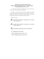
Basic Wiring Diagram
400
150
D2
Air Cooling
440
185
D2
Air Cooling
480
240
D3
Air Cooling
520
240
D3
Air Cooling
550
300
D3
Air Cooling
595
300
D3
Air Cooling
650
400
D4
Air Cooling