AN0853 PIC18XXX8 CAN driver with prioritized transmit buffer
Bạn đang xem bản rút gọn của tài liệu. Xem và tải ngay bản đầy đủ của tài liệu tại đây (211.29 KB, 38 trang )
M
AN853
PIC18XXX8 CAN Driver with Prioritized Transmit Buffer
Author:
Gaurang Kavaiya
Microchip Technology Inc.
INTRODUCTION
The Microchip PIC18XXX8 family of microcontrollers
provide an integrated Controller Area Network (CAN)
solution along with other PICmicro® features. Although
originally intended for the automotive industry, CAN is
finding its way into other control applications. In CAN, a
protocol message with highest priority wins the bus
arbitration and maintains the bus control. For minimum
message latency and bus control, messages should be
transmitted on a priority basis.
Because of the wide applicability of the CAN protocol,
developers are faced with the often cumbersome task
of dealing with the intricate details of CAN registers.
This application note presents a software library that
hides the details of CAN registers, and discusses the
design of the CAN driver with prioritized Transmit buffer
implementation. This software library allows
developers to focus their efforts on application logic,
while minimizing their interaction with CAN registers.
If the controller has heavy transmission loads, it is
advisable to use software Transmit buffers to reduce
message latency. Firmware also supports user defined
Transmit buffer size. If the defined size of a Transmit
buffer is more than that available in hardware (3), the
CAN driver will use 14 bytes of general purpose RAM
for each extra buffer.
For details about the PIC18 family of microcontrollers,
refer to the PIC18CXX8 Data Sheet (DS30475), the
PIC18FXX8 Data Sheet (DS41159), and the PICmicro®
18C MCU Family Reference Manual (DS39500).
2002 Microchip Technology Inc.
CAN MODULE OVERVIEW
The PIC18 family of microcontrollers contain a CAN
module that provides the same register and functional
interface for all PIC18 microcontrollers.
The module features are as follows:
• Implementation of CAN 1.2, CAN 2.0A and
CAN 2.0B protocol
• Standard and extended data frames
• 0 - 8 bytes data length
• Programmable bit rate up to 1 Mbit/sec
• Support for remote frame
• Double-buffered receiver with two prioritized
received message storage buffers
• Six full (standard/extended identifier) acceptance
filters: two associated with the high priority
receive buffer, and four associated with the low
priority receive buffer
• Two full acceptance filter masks, one each
associated with the high and low priority receive
buffers
• Three transmit buffers with application specified
prioritization and abort capability
• Programmable wake-up functionality with
integrated low-pass filter
• Programmable Loopback mode and
programmable state clocking supports
self-test operation
• Signaling via interrupt capabilities for all CAN
receiver and transmitter error states
• Programmable clock source
• Programmable link to timer module for
time-stamping and network synchronization
• Low Power SLEEP mode
DS00853A-page 1
AN853
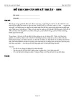
FIGURE 1:
CAN BUFFERS AND PROTOCOL ENGINE BLOCK DIAGRAM
Acceptance Mask
RXM1
BUFFERS
Acceptance Filter
RXF2
Message
Queue
Control
MESSAGE
MSGREQ
TXABT
TXLARB
TXERR
MTXBUFF
TXB2
MESSAGE
MSGREQ
TXABT
TXLARB
TXERR
MTXBUFF
TXB1
MESSAGE
MSGREQ
TXABT
TXLARB
TXERR
MTXBUFF
TXB0
A
c
c
e
p
t
R
X
B
0
Transmit Byte Sequencer
Acceptance Mask
RXM0
Acceptance Filter
RXF3
Acceptance Filter
RXF0
Acceptance Filter
RXF4
Acceptance Filter
RXF1
Acceptance Filter
RXF5
M
A
B
Identifier
Data Field
Data Field
PROTOCOL
ENGINE
Transmit
Logic
TX
DS00853A-page 2
RXERRCNT
TXERRCNT
Transmit
Error
Counter
CRC Generator
R
X
B
1
Identifier
Receive
Error
Counter
Transmit Shift
A
c
c
e
p
t
ErrPas
BusOff
Receive Shift
Protocol
Finite
State
Machine
CRC Check
Bit
Timing
Logic
Bit Timing
Generator
RX
2002 Microchip Technology Inc.
AN853
Bus Arbitration and Message Latency
In the CAN protocol, if two or more bus nodes start their
transmission at the same time, message collision is
avoided by bit-wise arbitration. Each node sends the
bits of its identifier and monitors the bus level. A node
that sends a recessive identifier bit, but reads back a
dominant one, loses bus arbitration and switches to
Receive mode. This condition occurs when the message identifier of a competing node has a lower binary
value (dominant state = logic 0), which results in the
competing node sending a message with a higher priority. Because of this, the bus node with the highest priority message wins arbitration, without losing time by
having to repeat the message. Transmission of the
lower priority message is delayed until all high priority
traffic on the bus is finished, which adds some latency
to the message transmission. This type of message
latency cannot be avoided.
Depending on software driver implementation,
additional latency can be avoided by proper design of
the driver. If CAN is working at low bus utilization, then
the delay in message transmission is not a concern
because of arbitration. However, if CAN bus utilization
is high, unwanted message latency can be reduced
with good driver design.
Additionally, consider the case where all buffers are
occupied with a low priority message and the controller
wants to transmit a high priority message. Since all
buffers are full, the high priority message will be
blocked until one of the low priority messages is
transmitted. The low priority message will be sent only
after all the high priority messages on the bus are sent.
This can considerably delay the transmission of high
priority messages.
How then, can this problem be solved? Adding more
buffers may help, but most likely the same situation will
occur. What then, is the solution? The solution is to
unload the lowest priority message from the transmit
buffer and save it to a software buffer, then load the
transmit buffer with the higher priority message. To
maintain bus control, all n Transmit buffers should be
loaded with n highest priority messages. Once the
transmit buffer is emptied, load the lower priority
message into the transmit buffer for transmission. To
do this, intelligent driver software is needed that will
manage these buffers, based on the priority of the
message (Lower binary value of identifier -> Higher
priority, see "Terminology Conventions" on page 5).
This method minimizes message latency for higher
priority messages.
To illustrate this point, let us examine latency that
occurs because of the implementation of driver
software. Consider the case when a buffer contains a
low priority message in queue and a high priority
message is loaded. If no action is taken, the
transmission of the high priority message will be
delayed until the low priority message is transmitted. A
PIC18CXX8 device provides a workaround for this
problem.
In PIC18CXX8 devices, it is possible to assign priority
to all transmit buffers, which causes the highest priority
message to be transmitted first and so on. By setting
the transmit buffer priority within the driver software,
this type of message latency can be avoided.
2002 Microchip Technology Inc.
DS00853A-page 3
AN853
EXAMPLE 2:
Macro Wrappers
One of the problems associated with assembly
language programming is the mechanism used to pass
parameters to a function. Before a function can be
called, all parameters must be copied to a temporary
memory location. This becomes quite cumbersome
when passing many parameters to a generalized
function. One way to facilitate parameter passing is
through the use of “macro wrappers”. This new concept
provides a way to overcome the problems associated
with passing parameters to functions.
A macro wrapper is created when a macro is used to
“wrap” the assembly language function for easy
access. In the following examples, macros call the
same function, but the way they format the data is
different. Depending on the parameters, different
combinations of macro wrappers are required to fit the
different applications.
Macro wrappers for assembly language functions
provide a high level ‘C-like’ language interface to these
functions, which makes passing multiple parameters
quite simple. Because the macro only deals with literal
values, different macro wrappers are provided to suit
different calling requirements for the same functions.
For example, if a function is used that copies the data
at a given address, the data and address must be supplied to the function.
#define
CODE WITH MACRO
WRAPPER
Address 0x1234
CopyData 0x56,
Address
The code in Example 3 shows variable data stored in
DataLoc.
EXAMPLE 3:
CODE WITHOUT MACRO
WRAPPER
#define
Address
UDATA
TempWord
DataLoc
RES
RES
banksel
movlw
movwf
movlw
movwf
banksel
movf
call
0x1234
02
01
TempWord
low(Address)
TempWord
high(Address)
TempWord+1
DataLoc
DataLoc,W
CopyDataFunc
Using a macro wrapper, the code shown in Example 4
supplies the memory address location for data instead
of supplying the data value directly.
EXAMPLES
Using standard methods, a call to the assembly language function CopyDataFunc might look like the
macro shown in Example 1.
EXAMPLE 1:
#define
UDATA
TempWord
banksel
movlw
movwf
movlw
movwf
movlw
call
CODE WITHOUT MACRO
WRAPPER
Address
RES
EXAMPLE 4:
#define
CODE WITH MACRO
WRAPPER
Address
UDATA
Dataloc
RES 01
CopyData_ID DataLoc,
0x1234
AddressLoc
0x1234
02
TempWord
low(Address)
TempWord
high(Address)
TempWord+1
0x56
;Copy data
CopyDataFunc
The code in Example 5 shows one more variation using
a macro wrapper for the code of both variable
arguments.
EXAMPLE 5:
UDATA
AddressLoc
Dataloc
CODE WITH MACRO
WRAPPER
RES 02
RES 01
CopyData_ID_IA DataLoc,
Using a macro wrapper, the code in Example 2 shows
how to access the same function that accepts the data
value directly.
DS00853A-page 4
AddressLoc
To summarize, the code examples previously
described call for the same function, but the way they
format the data is different. By using a macro wrapper,
access to assembly functions is simplified, since the
macro only deals with literal values.
2002 Microchip Technology Inc.
AN853
PIC18XXX8 CAN FUNCTIONS
All PIC18XXX8 CAN functions are grouped into the
following three categories:
• Configuration/Initialization Functions
• Module Operation Functions
• Status Check Functions
The following table lists each function by category,
which are described in the following sections.
TABLE 1:
FUNCTION INDEX
Function
Category
Page Number
CANInitialize
Configuration/Initialization
6
CANSetOperationMode
Configuration/Initialization
8
CANSetOperationModeNoWait
Configuration/Initialization
9
CANSetBaudRate
Configuration/Initialization
10
CANSetReg
Configuration/Initialization
12
CANSendMessage
Module Operation
16
CANReadMessage
Module Operation
19
CANAbortAll
Module Operation
22
CANGetTxErrorCount
Status Check
23
CANGetRxErrorCount
Status Check
24
CANIsBusOff
Status Check
25
CANIsTxPassive
Status Check
26
CANIsRxPassive
Status Check
27
CANIsRxReady
Status Check
28
CANIsTxReady
Status Check
30
Terminology Conventions
The following applies when referring to the terminology used in this application note.
TABLE 2:
TERMINOLOGY CONVENTIONS
Term
Meaning
xyzFunc
Used for original assembly language functions.
xyz
The macro that will accept all literal values.
xyz_I(First letter of argument)
The macro that will accept the memory address location for variable implementation.
xyz_D(First letter of argument) The macro that expects the user is directly copying the specified parameter at the
required memory location by assembly function.
LL:LH:HL:HH
bit 0
bit 31
HH
HL
LH
LL
8-bits
8-bits
8-bits
8-bits
2002 Microchip Technology Inc.
DS00853A-page 5
AN853
CONFIGURATION/INITIALIZATION FUNCTIONS
CANInitialize
This function initializes the PIC18 CAN module by the given parameters.
Function
CANInitializeFunc
Input
m_SJW
SJW value as defined in the PIC18CXX8 data sheet (must be between 1 and 4).
m_BRP
BRP value as defined in the PIC18CXX8 data sheet (must be between 1 and 64).
m_PHSEG1
PHSEG1 value as defined in the PIC18CXX8 data sheet (must be between 1 and 8).
m_PHSEG2
PHSEG2 value as defined in the PIC18CXX8 data sheet (must be between 1 and 8).
m_PROPSEG2
PROPSEG value as defined in the PIC18CXX8 data sheet (must be between 1 and 8).
m_Flags1
Flag value of type CAN_CONFIG_FLAGS.
This parameter can be any combination (AND’d together) of the following values:
TABLE 3: CAN_CONFIG_FLAG VALUES
Value
Meaning
Bit(s)
Position
Status(1)
CAN_CONFIG_DEFAULTS
Default flags
CAN_CONFIG_PHSEG2_
PRG_ON
Use supplied PHSEG2 value
1
CAN_CONFIG_PHSEG2_
PRG_BIT_NO
Set
CAN_CONFIG_PHSEG2_
PRG_OFF
Use maximum of PHSEG1 or
Information Processing Time
(IPT), whichever is greater
1
CAN_CONFIG_PHSEG2_
PRG_BIT_NO
Clear
CAN_CONFIG_LINE_
FILTER_ON
Use CAN bus line filter for
wake-up
1
CAN_CONFIG_LINE_
FILTER_BIT_NO
Set
CAN_CONFIG_LINE_
FILTER_OFF
Do not use CAN bus line
filter for wake-up
1
CAN_CONFIG_LINE_
FILTER_BIT_NO
Clear
CAN_CONFIG_SAMPLE_
ONCE
Sample bus once at the
sample point
1
CAN_CONFIG_SAMPLE_
BIT_NO
Set
CAN_CONFIG_SAMPLE_
THRICE
Sample bus three times prior
to the sample point
1
CAN_CONFIG_SAMPLE_
BIT_NO
Clear
CAN_CONFIG_ALL_MSG
Accept all messages
including invalid ones
2
CAN_CONFIG_MSG_BITS
CAN_CONFIG_VALID_
XTD_MSG
Accept only valid Extended
Identifier messages
2
CAN_CONFIG_MSG_BITS
CAN_CONFIG_VALID_
STD_MSG
Accept only valid Standard
Identifier messages
2
CAN_CONFIG_MSG_BITS
CAN_CONFIG_ALL_
VALID_MSG
Accept all valid messages
2
CAN_CONFIG_MSG_BITS
Note 1: If a definition has more than one bit, position symbol provides information for bit masking. ANDing it
with the value will mask all the bits except the required one. Status information is not provided, since
the user needs to use ANDing and ORing to set/get value.
DS00853A-page 6
2002 Microchip Technology Inc.
AN853
Return Values
None
Pre-condition
None
Side Effects
All pending CAN messages are aborted.
Remarks
This function does not allow the calling function to specify receive buffer mask and filter values. All mask registers are
set to 0x00, which essentially disables the message filter mechanism. If an application requires the message filter
operation, it must perform initialization in discrete steps. See CANSetReg for more information.
Macro
CANInitialize
SJW, BRP, PHSEG1, PHSEG2, PROPSEG, Flags
Input
SJW
SJW value as defined in the PIC18CXX8 data sheet (must be between 1 and 4).
BRP
BRP value as defined in the PIC18CXX8 data sheet (must be between 1 and 64).
PHSEG1
PHSEG1 value as defined in the PIC18CXX8 data sheet (must be between 1 and 8).
PHSEG2
PHSEG2 value as defined in the PIC18CXX8 data sheet (must be between 1 and 8).
PROPSEG
PROPSEG value as defined in the PIC18CXX8 data sheet (must be between 1 and 8).
Flags
Flag value of type CAN_CONFIG_FLAGS, as previously described.
Example 1
;Initialize for 125kbps@20MHz, all valid messages
CANInitialize 1, 5, 7, 6, 2, CAN_CONFIG_ALL_VALID_MSG
Example 2
;Initialize for 125kbps@20MHz, valid extended message and line filter on
CANInitialize 1, 5, 7, 6, 2, CAN_CONFIG_LINE_FILTER_ON & CAN_CONFIG_VALID_XTD_MSG
2002 Microchip Technology Inc.
DS00853A-page 7
AN853
CANSetOperationMode
This function changes the PIC18 CAN module Operation mode.
Function
CANSetOperationModeFunc
Input
W reg
Value of type CAN_OP_MODE.
This parameter must be only one of the following values:
TABLE 4: CAN_OP_MODE VALUES
Value
Meaning
CAN_OP_MODE_NORMAL
Normal mode of operation
CAN_OP_MODE_SLEEP
SLEEP mode of operation
CAN_OP_MODE_LOOP
Loopback mode of operation
CAN_OP_MODE_LISTEN
Listen Only mode of operation
CAN_OP_MODE_CONFIG
Configuration mode of operation
Return Values
None
Pre-condition
None
Side Effects
If CAN_OP_MODE_CONFIG is requested, all pending messages will be aborted.
Remarks
This is a blocking function. It waits for a given mode to be accepted by the CAN module and then returns the control. If
a non-blocking call is required, see the CANSetOperationModeNoWait function.
Macro
CANSetOperationMode OpMode
Input
OpMode
Value of type CAN_OP_MODE.
This parameter must be only one of the values listed in Table 4.
Example
...
CANSetOperationMode
CAN_OP_MODE_CONFIG
; Module is in CAN_OP_MODE_CONFIG mode.
...
DS00853A-page 8
2002 Microchip Technology Inc.
AN853
CANSetOperationModeNoWait
This macro changes the PIC18 CAN module Operation mode.
Macro
CANSetOperationModeNoWait
Input
W reg
Value of type CAN_OP_MODE.
This parameter must be only one of the values listed in Table 4.
Return Values
None
Pre-condition
None
Side Effects
If CAN_OP_MODE_CONFIG is requested, all pending messages will be aborted.
Remarks
This is a non-blocking function. It requests a given mode of operation and immediately returns the control. Caller must
make sure that the desired mode of operation is set before performing any mode specific operation. If a blocking call is
required, see the CANSetOperationMode function.
Example
...
CANSetOperationModeNoWait CAN_OP_MODE_CONFIG
2002 Microchip Technology Inc.
DS00853A-page 9
AN853
CANSetBaudRate
This function programs the PIC18 CAN module for given bit rate values.
Function
CANSetBaudRateFunc
Input
m_SJW
SJW value as defined in the PIC18CXX8 data sheet (must be between 1 and 4).
m_BRP
BRP value as defined in the PIC18CXX8 data sheet (must be between 1 and 64).
m_PHSEG1
PHSEG1 value as defined in the PIC18CXX8 data sheet (must be between 1 and 8).
m_PHSEG2
PHSEG2 value as defined in the PIC18CXX8 data sheet (must be between 1 and 8).
m_PROPSEG2
PROPSEG value as defined in the PIC18CXX8 data sheet (must be between 1 and 8).
m_Flags1
Flag value of type CAN_CONFIG_FLAGS.
This parameter can be any combination (AND’d together) of the values listed in Table 3.
Return Values
None
Pre-condition
PIC18 CAN module must be in the Configuration mode or else given values will be ignored.
Side Effects
None
Remarks
None
Macro
CANSetBaudRate
SJW, BRP, PHSEG1, PHSEG2, PROPSEG, Flags
Input
SJW
SJW value as defined in the PIC18CXX8 data sheet (must be between 1 and 4).
BRP
BRP value as defined in the PIC18CXX8 data sheet (must be between 1 and 64).
PHSEG1
PHSEG1 value as defined in the PIC18CXX8 data sheet (must be between 1 and 8).
PHSEG2
PHSEG2 value as defined in the PIC18CXX8 data sheet (must be between 1 and 8).
PROPSEG
PROPSEG value as defined in the PIC18CXX8 data sheet (must be between 1 and 8).
Flags
Flag value of type CAN_CONFIG_FLAGS as previously described.
DS00853A-page 10
2002 Microchip Technology Inc.
AN853
Example
...
CANSetOperationMode CAN_OP_MODE_CONFIG
;Set 125bps at 20MHz oscillator frequency
CANSetBaudRate 1, 5, 7, 6, 2,
CAN_CONFIG_SAMPLE_ONCE &
CAN_CONFIG_PHSEG2_PRG_OFF &
CAN_CONFIG_LINE_FILTER_ON
CANSetOperationMode CAN_OP_MODE_NORMAL
...
2002 Microchip Technology Inc.
DS00853A-page 11
AN853
CANSetReg
This function sets the PIC18 CAN module mask/filter values for the given receive buffer.
Function
CANSetRegFunc
Input
FSR0H:FSR0L
Starting address of 32-bit buffer to be updated.
Reg1:Reg1+3
32-bit mask/filter value that may correspond to 11-bit Standard Identifier or 29-bit Extended Identifier, with binary zero
padded on left. Reg1 = LL, Reg1+1 = LH, Reg1+2 = HL and Reg1+3 = HH byte (see "Terminology Conventions" on
page 5).
m_Flags1
Type of message Flag.
This parameter must be only one of the following values:
TABLE 5: CAN_CONFIG_MSG VALUES
Value
Meaning
Bit(s)
Position
CAN_CONFIG_STD_MSG
CAN_CONFIG_XTD_MSG
Status
Standard Identifier message
1
CAN_CONFIG_MSG_TYPE_BIT_NO
Set
Extended Identifier message
1
CAN_CONFIG_MSG_TYPE_BIT_NO
Clear
Return Values
None
Pre-condition
PIC18 CAN module must be in the Configuration mode or else given values will be ignored.
Side Effects
None
Remarks
None
Macro
CANSetReg RegAddr, val, Flags
Input
RegAddr
This parameter must be only one of the following values:
TABLE 6: REGISTER ADDRESS VALUES
Value
Meaning
CAN_MASK_B1
Receive Buffer 1 mask value
CAN_MASK_B2
Receive Buffer 2 mask value
CAN_FILTER_B1_F1
Receive Buffer 1, Filter 1 value
CAN_FILTER_B1_F2
Receive Buffer 1, Filter 2 value
CAN_FILTER_B2_F1
Receive Buffer 2, Filter 1 value
CAN_FILTER_B2_F2
Receive Buffer 2, Filter 2 value
CAN_FILTER_B2_F3
Receive Buffer 2, Filter 3 value
CAN_FILTER_B2_F4
Receive Buffer 2, Filter 4 value
DS00853A-page 12
2002 Microchip Technology Inc.
AN853
val
32-bit mask/filter value that may correspond to 11-bit Standard Identifier, or 29-bit Extended Identifier, with binary
zero padded on left.
Flags
Value of CAN_CONFIG type.
This parameter must be only one of the values listed in Table 6.
Macro
CANSetReg_IF RegAddr, val, FlagsReg
Input
RegAddr
This parameter must be only one of the values listed in Table 6.
val
32-bit mask/filter value that may correspond to 11-bit Standard Identifier, or 29-bit Extended Identifier, with binary
zero padded on left.
FlagsReg
Memory Address location that contains the Flag information. This parameter must be only one of the values listed
in Table 6.
Macro
CANSetReg_IV RegAddr, Var, Flags
Input
RegAddr
This parameter must be only one of the values listed in Table 6.
Var
Starting address of 32-bit buffer containing mask/filter value. Buffer storage format should be Low -> High
(LL:LH:HL:HH) byte (see "Terminology Conventions" on page 5).
32-bit mask/filter value that may correspond to 11-bit Standard Identifier, or 29-bit Extended Identifier, with binary
zero padded on left.
Flags
Value of CAN_CONFIG type. This parameter must be only one of the values listed in Table 6.
Macro
CANSetReg_IV_IF
RegAddr, Var, FlagsReg
Input
RegAddr
This parameter must be only one of the values listed in Table 6.
Var
Starting address of 32-bit buffer containing mask/filter value. Buffer storage format should be Low -> High
(LL:LH:HL:HH) byte (see "Terminology Conventions" on page 5).
32-bit mask/filter value that may correspond to 11-bit Standard Identifier, or 29-bit Extended Identifier, with binary
zero padded on left.
FlagsReg
Memory Address location that contains the Flag information. This parameter must be only one of the values listed
in Table 6.
2002 Microchip Technology Inc.
DS00853A-page 13
AN853
Macro
CANSetReg_DREG_IV_IF
Var, FlagsReg
Input
FSR0H:FSR0L
FSR0 contains starting address of 32-bit buffer to be updated. This buffer must be of the mask/filter type. The
starting address is the address of the SIDH register for that mask/filter.
Var
Starting address of 32-bit buffer containing mask/filter value. Buffer storage format should be Low -> High
(LL:LH:HL:HH) byte (see "Terminology Conventions" on page 5).
32-bit mask/filter value that may correspond to 11-bit Standard Identifier, or 29-bit Extended Identifier, with binary
zero padded on left.
FlagsReg
Memory Address location that contains the Flag information. This parameter must be only one of the values listed
in Table 6.
Macro
CANSetReg_DREG_DV_IF
FlagsReg
Input
FSR0H:FSR0L
FSR0 contains starting address of 32-bit buffer to be updated. This buffer must be of the mask/filter type. The
starting address is the address of the SIDH register for that mask/filter.
Reg1:Reg1+3
Starting address of 32-bit buffer containing mask/filter value. Buffer storage format should be Low -> High
(Reg1 = LL:Reg1+1 = LH:Reg1+2 = HL:Reg1+3 = HH) byte (see "Terminology Conventions" on page 5).
32-bit mask/filter value that may correspond to 11-bit Standard Identifier, or 29-bit Extended Identifier, with binary
zero padded on left.
FlagsReg
Memory Address location that contains the Flag information. This parameter must be only one of the values listed
in Table 6.
Example
...
CANSetReg
CANSetReg
CANSetReg
CANSetReg
CANSetReg
CANSetReg
CANSetReg
CANSetReg
CAN_MASK_B1, 0x00000001, CAN_STD_MSG
CAN_MASK_B2, 0x00008001, CAN_XTD_MSG
CAN_FILTER_B1_F1, 0x0000, CAN_STD_MSG
CAN_FILTER_B1_F2, 0x0001, CAN_STD_MSG
CAN_FILTER_B2_F1, 0x8000, CAN_XTD_MSG
CAN_FILTER_B2_F2, 0x8001, CAN_XTD_MSG
CAN_FILTER_B2_F3, 0x8002, CAN_XTD_MSG
CAN_FILTER_B2_F4, 0x8003, CAN_XTD_MSG
UDATA
Flags
RES
01
;Memory location Flags contains configuration flags
;information (Indirect Flag info (pointer to Flag))
CANSetReg_IF CAN_MASK_B1, 0x00000001, Flags
DS00853A-page 14
2002 Microchip Technology Inc.
AN853
UDATA
IDVal
RES
04
;32-bit memory location IDVal contains 32-bit mask
;value (Indirect value info (pointer to value))
CANSetReg_IV CAN_MASK_B2, IDVal, CAN_XTD_MSG
UDATA
Flags
IDVal
RES
RES
01
04
;32-bit memory location IDVal contains 32-bit mask
;value (Indirect value info (pointer to value))
;Memory location Flags contains configuration flags
;information (Indirect Flag info (pointer to Flag))
CANSetReg_IV_IF CAN_FILTER_B1_F1, IDVal, Flags
UDATA
Flags
IDVal
RES
RES
01
04
;32-bit memory location IDVal contains 32-bit mask
;value (Indirect value info (pointer to value))
;Memory location Flags contains configuration flags
;information (Indirect Flag info (pointer to Flag))
movlw
movwf
movlw
movwf
low(RxF0SIDH)
FSR0L
high(RxF0SIDH)
FSR0H
;Because of above or some other operation FSR0
;contains starting address of buffer (xxxxSIDH reg.)
;for mask/filter value storage.
CANSetReg_DREG_IV_IF IDVal, Flags
UDATA
Flags
RES
01
;32-bit memory location IDVal contains 32-bit mask
;value (Indirect value info (pointer to value))
;Memory location Flags contains configuration flags
;information (Indirect Flag info (pointer to Flag))
movlw
movwf
movlw
movwf
low(RxF0SIDH)
FSR0L
high(RxF0SIDH)
FSR0H
;Because of above or some other operation FSR0
;contains starting address of buffer (xxxxSIDH reg.)
;for mask/filter value storage.
;Reg1:Reg1+3 contains 32-bit ID value.
CANSetReg_DREG_DV_IF Flags
2002 Microchip Technology Inc.
DS00853A-page 15
AN853
MODULE OPERATION FUNCTIONS
CANSendMessage
This function copies the given message to one of the empty transmit buffers and marks it as ready to be transmitted.
Function
CANSendMessageFunc
Input
Reg1:Reg1+3
32-bit identifier value that may correspond to 11-bit Standard Identifier, or 29-bit Extended Identifier, with binary zero
padded on left. Exact number of bits to use depends on M_TxFlags. Buffer storage format should be Low -> High
(Reg1 = LL:Reg1+1 = LH:Reg1+2 = HL:Reg1+3 = HH) byte (see "Terminology Conventions" on page 5).
FSR1H:FSR1L
Starting address of data buffer.
m_DataLength
Number of bytes to send.
m_TxFlags
Value of type CAN_TX_MSG_FLAGS.
This parameter can be any combination (AND’d together) of the following group values:
TABLE 7: CAN_TX_MSG_FLAGS VALUES
Value
Meaning
Bit(s)
Position
Status
CAN_TX_STD_FRAME
Standard Identifier message
1
CAN_TX_FRAME_BIT_NO
CAN_TX_XTD_FRAME
Extended Identifier message
1
CAN_CONFIG_MSG_TYPE_BIT_NO Clear
CAN_TX_NO_RTR_FRAME
Regular message - not RTR
1
CAN_TX_RTR_BIT_NO
Set
CAN_TX_RTR_FRAME
RTR message
1
CAN_TX_RTR_BIT_NO
Clear
Set
Return Values
W =1, if the given message was successfully placed in one of the empty transmit buffers.
W= 0, if all transmit buffers were full.
Pre-condition
None
Side Effects
None
Remarks
None
Macro
CANSendMessage
msgID, DataPtr, DataLngth, Flags
msgID
32-bit identifier value that may correspond to 11-bit Standard Identifier, or 29-bit Extended Identifier, with binary zero
padded on left. Exact number of bits to use depends on Flags.
DS00853A-page 16
2002 Microchip Technology Inc.
AN853
DataPtr
Pointer to zero or more of data bytes to send.
DataLngth
Number of bytes to send.
Flags
Value of type CAN_TX_MSG_FLAGS.
This parameter can be any combination (AND’d together) of the group values listed in Table 7.
Macro
CANSendMessage_IID_IDL_IF
msgIDPtr, DataPtr, DataLngthPtr, FlagsReg
msgIDPtr
Starting address of memory location containing 32-bit message ID. Buffer storage format should be Low -> High
(LL:LH:HL:HH) byte (see "Terminology Conventions" on page 5).
32-bit identifier value that may correspond to 11-bit Standard Identifier, or 29-bit Extended Identifier, with binary zero
padded on left. Exact number of bits to use depends on FlagsReg.
DataPtr
Pointer to zero or more of data bytes to send.
DataLngth
Memory Address location having data of number of bytes to send.
FlagsReg
Memory Address location that contains the Flag information. Flags must be of type CAN_TX_MSG_FLAGS.
This parameter can be any combination (AND’d together) of the group values listed in Table 7.
Example A
UDATA
MessageData
call
bnc
movlw
movwf
movlw
movwf
RES
02
CANIsTxReady
TxNotRdy
0x01
MessageData
0x02
MessageData+1
;Copy Data byte 1
;Copy Data byte 2
CANSendMessage 0x20,
MessageData,
2,
CAN_TX_STD_FRAME &
CAN_TX_NO_RTR_FRAME
TxNotRdy:
;All Buffer are full, Try again
2002 Microchip Technology Inc.
DS00853A-page 17
AN853
Example B
UDATA
MessageData
movlw
movwf
movlw
movwf
RES
02
0x01
MessageData
0x02
MessageData+1
;Copy Data byte 1
;Copy Data byte 2
CANSendMessage 0x20,
MessageData,
2,
CAN_TX_STD_FRAME &
CAN_TX_NO_RTR_FRAME
addlw
0x00
;Check for return value 0 in W
bz
TxNotRdy
;Buffer Full, Try again
;Message is copied in buffer for Transmission. It will be
;transmitted based on priority and pending messages in
;buffers
nop
;Application specific code
TxNotRdy:
;All Buffer are full, Message was not copied in buffer for
;Transmission
...
UDATA
MessageData
RES
02
Idval
RES
04
DataLength
RES
01
Flags
RES
01
call
bnc
movlw
movwf
movlw
movwf
movwf
CANIsTxReady
TxNotRdy
0x01
MessageData
0x02
MessageData+1
DataLength
;Copy Data byte 1
;Copy Data byte 2
;Set Data length to 2
;IDval contains 32-bit message ID and Flags
;contains TX Flags info.
CANSendMessage_IID_IDL_IF
IDval,
MessageData,
DataLength,
Flags
TxNotRdy:
;All Buffer are full, Try again
DS00853A-page 18
2002 Microchip Technology Inc.
AN853
CANReadMessage
This function copies the new available message to the user supplied buffer.
Function
CANReadMessageFunc
Input
FSR0H:FSR0L
Starting address for received data storage.
Output
Temp32Data:Temp32Data+3
Received Message ID. Buffer storage format is Low -> High (LL:LH:HL:HH) byte (see "Terminology Conventions"
on page 5).
32-bit identifier value that may correspond to 11-bit Standard Identifier, or 29-bit Extended Identifier, with binary zero
padded on left.
DataLen
Number of bytes received.
m_RxFlags
Value of type CAN_RX_MSG_FLAGS.
This parameter can be any combination (AND’d together) of the following values. If a flag bit is set, the
corresponding meaning is TRUE; if cleared, the corresponding meaning is FALSE.
TABLE 8: CAN_RX_MSG_FLAGS VALUES
Value
Meaning
Bit(s)
CAN_RX_FILTER_1,
CAN_RX_FILTER_2,
CAN_RX_FILTER_3,
CAN_RX_FILTER_4,
CAN_RX_FILTER_5,
CAN_RX_FILTER_6
Receive buffer filter that
caused this message to
be accepted.
3
CAN_RX_FILTER_BITS
CAN_RX_OVERFLOW
Receive buffer overflow
condition
1
CAN_RX_OVERFLOW_BIT_NO
Set
CAN_RX_INVALID_MSG
Invalid message
1
CAN_RX_INVALID_MSG_BIT_NO
Set
CAN_RX_XTD_FRAME
Extended message
1
CAN_RX_XTD_FRAME_BIT_NO
Set
CAN_TX_RTR_FRAME
RTR message
1
CAN_RX_RTR_FRAME_BIT_NO
Set
1
CAN_RX_DBL_BUFFERED_BIT_NO
Set
CAN_RX_DBL_BUFFERED This message was
double-buffered
Position
Status
Return Values
W =1, if new message was copied to given buffer.
W= 0, if no new message was found.
Pre-condition
id, Data, DataLen and MsgFlags pointers must point to valid/desired memory locations.
Side Effects
None
Remarks
This function will fail if there are no new message(s) to read. Caller may check the return value to determine new
message availability, or may call CANIsRxReady function.
2002 Microchip Technology Inc.
DS00853A-page 19
AN853
Macro
CANReadMessage msgIDPtr, DataPtr, DataLngth, Flags
msgIDPtr
Starting address of 32-bit buffer for message ID storage. Buffer storage format is Low -> High (LL:LH:HL:HH) byte
(see "Terminology Conventions" on page 5). 32-bit identifier value that may correspond to 11-bit Standard Identifier,
or 29-bit Extended Identifier, with binary zero padded on left.
DataPtr
Starting address of data buffer for storage of received data byte.
DataLngth
Address of the memory location for storage of number of bytes received.
Flags
Address of the memory location for storage of number of bytes received.
Value of type CAN_RX_MSG_FLAGS.
This parameter can be any combination (AND’d together) of the values listed in Table 8. If a flag bit is set, the
corresponding meaning is TRUE; if cleared, the corresponding meaning is FALSE.
Example A
UDATA
NewMessage
NewMessageData
NewMessageLen
NewMessageFlags
RxFilterMatch
04
08
01
01
01
call
bnc
CANIsRxReady
RxNotRdy
CANReadMessage
NewMessage,
NewMessageData,
NewMessageLen,
NewMessageFlags
banksel
NewMessageFlags
btfsc
bra
NewMessageFlags,CAN_RX_OVERFLOW_BIT_NO
RxOvrFlow
;Branch to Logic for Rx
;overflow occurred.
btfsc
bra
NewMessageFlags,CAN_RX_INVALID_MSG_BIT_NO
RxInvldMsg
;Branch to Logic for Invalid
;Message received
btfsc
nop
NewMessageFlags,CAN_RX_XTD_FRAME_BIT_NO
;Logic for Extended frame
;received
;Else logic for standard
;frame received
nop
btfsc
bra
nop
DS00853A-page 20
RES
RES
RES
RES
RES
NewMessageFlags,CAN_RX_RTR_FRAME_BIT_NO
RxRTRFrame
;Branch to Logic for RTR
;frame received
;Regular frame received
2002 Microchip Technology Inc.
AN853
movlw
andwf
movwf
CAN_RX_FILTER_BITS
NewMesageFlags,W
RxFilterMatch
;Save matched Filter ;number
RxNotReady:
;Receive buffer is empty, Wait for new message
...
Example B
UDATA
NewMessage
NewMessageData
NewMessageLen
NewMessageFlags
RxFilterMatch
CANReadMessage
RES
RES
RES
RES
RES
04
08
01
01
01
NewMessage,
NewMessageData,
NewMessageLen,
NewMessageFlags
xorlw
bnz
0x01
RxNotReady
banksel
NewMessageFlags
btfsc
bra
NewMessageFlags,CAN_RX_OVERFLOW_BIT_NO
RxOvrFlow
;Branch to Logic for Rx
;overflow occurred.
btfsc
bra
NewMessageFlags,CAN_RX_INVALID_MSG_BIT_NO
RxInvldMsg
;Branch to Logic for Invalid
;Message received
btfsc
nop
NewMessageFlags,CAN_RX_XTD_FRAME_BIT_NO
;Logic for Extended frame
;received
;Else logic for standard
;frame received
nop
btfsc
bra
;Check for Success code
nop
NewMessageFlags,CAN_RX_RTR_FRAME_BIT_NO
RxRTRFrame
;Branch to Logic for RTR
;frame received
;Regular frame received
movlw
andwf
movwf
CAN_RX_FILTER_BITS
NewMesageFlags,W
RxFilterMatch
;Save matched Filter ;number
RxNotReady:
;Receive buffer is empty, Wait for new message
2002 Microchip Technology Inc.
DS00853A-page 21
AN853
CANAbortAll
This macro aborts all pending messages from the PIC18 CAN module. See the PIC18CXX8 Data Sheet for rules
regarding message abortion.
Macro
CANAbortAll
Input
None
Return Values
None
Pre-condition
None
Side Effects
None
Remarks
None
Example
...
CANAbortAll
...
DS00853A-page 22
2002 Microchip Technology Inc.
AN853
STATUS CHECK FUNCTIONS
CANGetTxErrorCount
This macro returns the PIC18 CAN transmit error count, as defined by BOSCH CAN Specifications, in WREG. See the
PIC18CXX8 Data Sheet for more information.
Macro
CANGetTxErrorCount
Input
None
Return Values
WREG contains the current value of transmit error count.
Pre-condition
None
Side Effects
None
Remarks
None
Example
UDATA
TxErrorCount
RES
01
...
CANGetTxErrorCount
;Returns error count in W
banksel
TxErrorCount
movwf
TxErrorCount
...
2002 Microchip Technology Inc.
DS00853A-page 23
AN853
CANGetRxErrorCount
This macro returns the PIC18 CAN receive error count, as defined by BOSCH CAN Specifications, in WREG. See the
PIC18CXX8 Data Sheet for more information.
Macro
CANGetRxErrorCount
Input
None
Return Values
WREG contains the current value of receive error count.
Pre-condition
None
Side Effects
None
Remarks
None
Example
UDATA
RxErrorCount
RES
01
...
CANGetRxErrorCount
; Returns error count in W
banksel
RxErrorCount
movwf
RxErrorCount
...
DS00853A-page 24
2002 Microchip Technology Inc.
AN853
CANIsBusOff
This function returns the PIC18 CAN module On/Off state.
Function
CANIsBusOff
Input
None
Return Values
Carry C = 1, if PIC18 CAN module is in the Bus Off state.
Carry C = 0, if PIC18 CAN module is in the Bus On state.
Pre-condition
None
Side Effects
None
Remarks
None
Example
...
call
bnc
nop
CANBusNotOff
nop
2002 Microchip Technology Inc.
CANIsBusOff()
CANBusNotOff
;CAN Module is in Bus off state
;CAN Module isn’t in Bus off state
DS00853A-page 25