AN1247 communication device class (CDC) host
Bạn đang xem bản rút gọn của tài liệu. Xem và tải ngay bản đầy đủ của tài liệu tại đây (351.61 KB, 18 trang )
AN1247
Communication Device Class (CDC) Host
Author:
Amardeep Gupta
Microchip Technology Inc.
INTRODUCTION
With the introduction of Microchip’s microcontroller with
USB OTG (Universal Serial Bus On-The-Go) peripheral, implementing an embedded host has become
easier. USB is used in several types of communication
devices. The USB specification defines an architecture
that is capable of supporting most communication
devices which use the USB Communications Device
Class (CDC).
This application note describes how to develop a USB
CDC application using a Microchip USB OTG
microcontroller as the embedded host.
COMMUNICATIONS DEVICE
OVERVIEW
Several types of communication can benefit from USB.
The CDC specification provides a set of rules for all
communication devices. Three classes define
communication devices:
• Communications Interface Class (CIC) – The CIC
defines a general purpose mechanism that can be
used to enable all types of communication
services on the USB. This interface consists of
two elements:
- A management element
The management element configures and
controls the device; it consists of Endpoint 0.
- A notification element
The notification element is optional and is used
to handle transport events. The notification
element can be used to transfer information
from device to host, which may then prompt the
host to initiate a transfer over the management
element. For example, it can be used for flow
control signals for RS-232 emulation devices.
• Data Interface Class (DIC) – The DIC defines a
general purpose mechanism to enable bulk or isochronous transfer on the USB when the data does
not meet the requirements for any other class.
This interface is used to transmit/receive data
to/from the device. Endpoints belonging to a DIC
are either isochronous or bulk, and normally exist
in pairs of the same type (one IN and one OUT).
• Communications Device Class (CDC) – The CDC
is a device-level definition, and is used by the host
to identify a communications device that may
present several different types of interfaces.
© 2009 Microchip Technology Inc.
DS01247A-page 1
AN1247
Class-Specific Codes
This section provides CDC, CIC and DIC codes,
including the subclasses and protocols supported in
the current version of the stack. The current version
of Microchip CDC host stack supports RS-232 emulation over USB. The succeeding sections provide
codes to support this functionality.
Table 3 provides the currently supported subclass
codes for the CIC:
TABLE 3:
COMMUNICATIONS
SUBCLASS CODE
Code
02h
Class
Abstract Control Model
Table 1 provides the CDC code:
TABLE 1:
COMMUNICATIONS DEVICE
CLASS CODE
Code
Class
02h
Communications Device Class
COMMUNICATIONS
INTERFACE CLASS CODE
Code
02h
Class
Communications Interface Class
The CDC specification provides various subclasses.
The current version of the Microchip CDC host stack
supports below mentioned subclasses.
DS01247A-page 2
TABLE 4:
supported
COMMUNICATIONS CLASS
PROTOCOL CODE
Code
01h
Table 2 provides the CIC code:
TABLE 2:
Table 4
provides
the
currently
communications class protocol codes:
Class
AT Commands: V.250, etc.
Table 5 provides the DIC code:
TABLE 5:
Code
0Ah
DATA INTERFACE CLASS
CODE
Class
Data Interface Class
No specific subclass and protocol codes are required to
achieve RS-232 functionality over USB.
© 2009 Microchip Technology Inc.
AN1247
Communication and Data Transfer
Handling
USBHostCDC_Api_ACM_Request() interface function. The following standard class-specific requests are
currently implemented:
Communication Management: The CDC client driver
takes care of enumerating the device connected on the
bus. The application must define the line coding parameters in the usb_config.h file; the USBConfig utility
can be used to set these parameters. If the connected
device complies with the settings, then the device will
be successfully attached to the bus; otherwise, it will
not be attached. If the application needs to change the
settings dynamically after the device has been
successfully enumerated, it can be done using the
TABLE 6:
• Class-Specific Requests – An Abstract Control
Model (ACM) communications device uses a
CDC interface for device management with a
communications subclass code of abstract
control.
Table 6 provides the only class-specific request codes
that are valid, and are supported for a CDC interface
with a communications subclass code of ACM.
CLASS SPECIFIC REQUESTS
Command Name
bmRequestType bRequest wValue wIndex
Data
wLength
SendEncapsulatedCommand
0x21
0
0
Interface Amount of data in Control
bytes associated Protocol-Based
with this recipient Command
GetEncapsulatedResponse
0xA1
1
0
Interface Amount of data in Protocol
bytes associated Dependent Data
with this recipient
SetLineCoding
0x21
0x20
0
Interface
7
Line Coding Data
Structure
GetLineCoding
0xA1
0x21
0
Interface
7
Line Coding Data
Structure
SetControlLineState
0x21
0x22
2
Interface
0
None
SendEncapsulatedCommand
SetLineCoding
This request is used to issue a command in the format
of the supported control protocol of the communications class interface. The specification requires this
request support.
This request allows the host to specify character format
properties, which might be required by some applications. This is especially required in RS-232 emulation.
For this application, the host and device must be aware
of data rate, parity, number of Stop bits, etc. This
applies to data transfers from the host to the device,
and from the device to the host. The line coding data
structure is defined in Table 7.
GetEncapsulatedResponse
This request is used to request a response in the
format of the supported control protocol of the communications class interface. The specification requires this
request support.
© 2009 Microchip Technology Inc.
DS01247A-page 3
AN1247
GetLineCoding
SetControlLineState
This request allows the host to find currently configured
line coding parameters. The line coding data structure
is defined in Table 7.
This request generates flow control signals for RS-232
communications. Table 8 provides the bitmap details
for the Control Line Signal (CLS).
TABLE 7:
TABLE 8:
Offset
0
LINE CODING DATA DETAILS
Field
dWDTERate
Size
(Bytes)
4
Description
Bit Position
Data terminal rate
in bits per sec.
4
bCharFormat
1
Stop Bits
0-1 Stop Bit
1-1.5 Stop Bits
2-2 Stop Bits
5
bParityType
1
Parity
0 = None
1 = Odd
2 = Even
3 = Mark
4 = Space
6
bDataBits
1
Data bits (5, 6, 7,
8 or 16)
DS01247A-page 4
BITMAP DETAILS FOR
CONTROL LINE SIGNAL
15...2
Description
Reserved
1
Carrier control signal, corresponds
to RTS signal in RS-232.
0 = Deactivate Carrier
1 = Activate Carrier
0
Indicates to DCE if DTE is present
or not; corresponds to DTR signal in
RS-232.
0 = Not Present
1 = Present
Note:
For a detailed specification on Communications Device Class (CDC) and
Abstract Control Mode (ACM), refer to
“Universal Serial Bus Class Definitions for
Communication Devices” at:
.
© 2009 Microchip Technology Inc.
AN1247
THE CDC CLIENT DRIVER
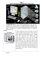
Architecture of CDC Client Driver
The host functionality is a multilayer stack (see
Figure 1) with different components of Microchip’s USB
embedded host support package contributing to different layers. The user application interacts with the CDC
client driver by using the interface function provided in
the usb_host_cdc_interface.h file.
FIGURE 1:
USB CDC HOST
ARCHITECTURE
Application Layer (RS-232 Emulation...)
CDC – ACM Interface Layer
USB EMBEDDED HOST LAYER
The USB embedded host layer provides basic USB
embedded host support. The interface to this layer is
provided automatically in the CDC client driver. For
more information about this layer, refer to Microchip's
AN1140, “USB Embedded Host Stack” and AN1141,
“USB Embedded Host Stack Programmer’s Guide”. It
is not necessary to be familiar with this layer’s
operation or configuration to use it with the CDC
application.
CDC – ACM CLASS CLIENT AND INTERFACE
LAYER
The next layer provides the client driver for the CDC
class. The current version of the stack supports the
ACM subclass only. The client driver enumerates the
connected device, and manages all the CDC related
transfers. This layer also provides interface functions to
the application layer. Each of these interface functions
is explained individually in subsequent sections.
Note:
CDC – ACM Class Client Driver
USB Embedded Host Layer
© 2009 Microchip Technology Inc.
For detailed information about the USB
host CDC driver APIs, refer to the API documentation provided in the Help directory
in the firmware download. The firmware is
available at www.microchip.com/usb.
DS01247A-page 5
AN1247
Using the CDC Client Driver
Configuring the USB CDC Class
This section provides a brief overview of the installation
and configuration procedures. For detailed information
on installation and configuration, refer to AN1140, “USB
Embedded Host Stack” and AN1141, “USB Embedded
Host Stack Programmer’s Guide”.
Use the configuration tool, USBConfig.exe, to
configure the CDC client driver for an application. This
tool is installed in the .\Microchip\USB
directory. Succeeding sections briefly describe the
configuration of USBConfig.exe.
Installing the CDC Client Driver
MAIN TAB
The CDC client driver is installed as part of the complete
USB embedded host support package, available on the
Microchip web site ( />
For the CDC Client driver for the USB embedded host,
the ‘USB Embedded Host’ radio button in the Main tab
will be selected by default, as displayed in Figure 2.
Select the Target Device Family.
FIGURE 2:
DS01247A-page 6
USB CONFIGURATION – MAIN TAB
© 2009 Microchip Technology Inc.
AN1247
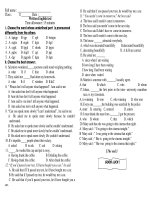
HOST TAB
1.
2.
3.
4.
Click the Host tab to configure basic host operation, as displayed in Figure 3. The CDC client
driver requires support for control and bulk
endpoints.
Under Transfer Types, select the Support Bulk
Transfers check box and enter the allowed
number of NAKs in the text box. If the report from
the device is not available, the device NAK would
be the response received by the host. Configure
the Number of NAKs Allowed field in sync with
the implementation on the device end.
Unselect the Support Interrupt Transfers and
Support Isochronous Transfers check boxes
if the application does not contain classes that
require interrupt or isochronous endpoints.
FIGURE 3:
5.
6.
Some devices also require longer than the USB
specification of 100 ms to initialize after powerup; it is recommended to increase the attach
debounce interval.
Enter the name of the function in the main
source file that serves as the application level
event handler.
Select the Generate Transfer Events check
box to use transfer events (EVENT_TRANSFER)
from the USB host layer. Refer to the “Event
Generation” section for more information on
transfer events.
USB CONFIGURATION – HOST TAB
© 2009 Microchip Technology Inc.
DS01247A-page 7
AN1247
CDC TAB
2.
The USB CDC client driver can either poll the USB host
driver for transfer status or respond to the USB host
driver transfer events.
3.
1.
Select the CDC tab.
FIGURE 4:
DS01247A-page 8
Select the CDC Client is used in Host mode
check box to enable support for a CDC
embedded host, as displayed in Figure 4.
Select the settings for RS-232 emulation. Select
Baud Rate, Data Bits, Parity and Stop Bits
default settings to be supported by the device.
USB CONFIGURATION – CDC TAB
© 2009 Microchip Technology Inc.
AN1247
TPL TAB
• Select the TPL tab and add support for the
CDC/ACM devices.
The standard ACM class supports two interfaces.
• Add TPL entries for the communication interface
and data interface.
FIGURE 5:
USB CONFIGURATION – TPL TAB
Client Driver Callback Handlers
The CDC client driver requires two callback handlers in
the interface layer. These callback handlers have been
defined in the file, usb_host_cdc.c.
• Initialization Event Handler
This is called after the peripheral has been
enumerated and initialized by the host layer. The
initialization handler is of the type defined by the
typedef:
typedef BOOL (*USB_CLIENT_INIT) (BYTE
address, DWORD flags);
This function performs initialization specific to the
device. If initialization occurs with no error, this
routine returns TRUE; otherwise, this routine
returns FALSE.
© 2009 Microchip Technology Inc.
• Event Handler
This is required to handle events that occur during
normal operation. This event handler is of the type
defined by the typedef:
typedef BOOL (*USB_CLIENT_EVENT_HANDLER)(BY
TE address, USB_EVENT event, void*data,
DWORD size);
For example, the EVENT_DETACH event occurs
when a device has detached from the bus. In this
case, the interface layer will update its status by
doing operations, such as removal of the device
from its list of attached devices. See the API documentation provided in the Help directory for a
complete list of events.
The host layer requires a list of the client driver’s
interfaces for peripheral initialization and event
handling. This list is defined automatically by the
configuration tool, USBConfig.exe, provided
with the stack.
DS01247A-page 9
AN1247
EVENT GENERATION
The CDC client driver can be configured to utilize transfer events (EVENT_TRANSFER) from the USB host layer
and CDC client driver layer. If the USB embedded host
transfer events are used, the application would require
more program and data memory, but the application
processing will be more efficient. The USB embedded
host transfer event configuration is transparent to the
interface layer.
Note:
Although the USB embedded host uses
USB interrupts, transfer event generation from the host driver layer to the
client driver is triggered by a polling
mechanism. This is to ensure that the
USB Interrupt Service Routine (ISR)
completes in a timely fashion. For more
information on the host driver, refer to
AN1140, “USB Embedded Host Stack”
and AN1141, “USB Embedded Host
Stack Programmer's Guide”.
DS01247A-page 10
The choice of whether or not to use the USB embedded
host transfer events depends on the implementation in
the application layer. The CDC client driver generates
the following events:
• EVENT_CDC_ATTACH – This event indicates
that a valid CDC device is attached and the
application can initiate transfers.
• EVENT_CDC_COMM_READ_DONE – This event
indicates that a Bulk IN transfer, initiated by the
application on the management interface, is
complete.
• EVENT_CDC_DATA_READ_DONE – This event
indicates that a Bulk IN transfer, initiated by the
application on the data interface, is complete.
• EVENT_CDC_COMM_WRITE_DONE – This event
indicates that a Bulk OUT transfer, initiated by the
application on the management interface, is
complete.
• EVENT_CDC_DATA_WRITE_DONE – This event
indicates that a Bulk OUT transfer, initiated by the
application on the data interface, is complete.
• EVENT_CDC_NAK_TIMEOUT – This event indicates that the NAK time-out has occurred. If the
IN transfer request rate is high, or the device does
not have any data to send, it will NAK the request.
The device will NAK unless it has data to transfer.
In this scenario, the CDC client will always be
busy and cannot service any other request. To
avoid this, it is advised to time-out the request.
The application must handle this time-out event
and re-initiate the IN transfer after an appropriate
delay. This delay can be calculated from the baud
rate defined by the application. It is recommended
to keep 5-10 number of NAKs allowed while configuring the stack. As explained in the previous section, this NAK count should be sufficient since the
application takes care of rescheduling the transfer.
In the demo application ‘USB Host – CDC – Serial
Demo’ the internal timer is used to schedule the
transfer. This is one of the ways that the application
periodically requests data from the device.
© 2009 Microchip Technology Inc.
AN1247
CLIENT DRIVER INITIALIZATION
The USB configuration tool provides a macro,
USBInitialize(), to call all of the initialization
routines required by the USB embedded host layer.
Normal Client Driver Operation
Normal background operation is performed by the void
USBHostCDCTasks(void); function.
This routine must be called on a regular basis to allow
device operation. The polling rate is not critical, since
most of the actual transfer of information is handled
through the USB interrupt. Since an application may
support multiple classes, this function does not call the
USBHostTasks() function. The USB configuration
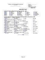
FIGURE 6:
tool will provide the USBTasks() macro to call all of
the background task routines required by the USB host
driver and the supported client drivers. This macro
must be called on a regular basis to ensure proper
functioning of host and client drivers. Once the device
is detected, the host layer enumerates the device and
calls back the CDC client layer to initialize the
interfaces.
CDC/ACM class is used to emulate the virtual COM
port. The CDC/ACM client enumerates the attached
CDC device. The client driver validates the COM port
settings on the attached device against the settings
configured on the client using the USBConfig.exe
utility. Figure 6 illustrates the enumeration process of
the CDC/ACM device.
USB CDC DEVICE ENUMERATION FLOW
USBHostCDCInitialize
Parse Communications Interface
(This includes Function Header,
Call Management Header,
ACM Header, Union Descriptors)
Parse Data Interface
(This includes Endpoint Descriptor)
GET_LINE_CODING
(Request for COM Port Settings
on the Device)
Check if COM Port
Settings are as Expected
by the Host
NO
SET_LINE_CODING
(Send COM Port Setting to the Device)
If Device can Support
the Requested Settings
YES
NO
Do Not Connect the Device on the Bus
STATE_RUNNING
Device is Ready for
Data Transfers
© 2009 Microchip Technology Inc.
DS01247A-page 11
AN1247
PERFORMING A TRANSFER
Normal communication with the device can be initiated
after the device is enumerated.
• USBHostCDC_ApiDeviceDetect()
This function is used to get the status of the device.
If the device is connected and ready for transfer,
then the function returns TRUE. If the transfer
events are enabled, then the application is notified
by the EVENT_CDC_ATTACH event.
Once the device is attached, the application is ready to
start data transfers. Usually two endpoints, one in each
direction, are supported by the device.
• BOOL USBHostCDC_Api_Get_IN_Data(BYTE
no_of_bytes, BYTE* data)
This function is used to receive data from the
device at a rate dependant on the baud rate settings. The application can use a timer interrupt to
precisely set up the request. A maximum of
64 bytes can be received in a single transfer.
Note:
The current version of the CDC client
driver is tested for full-speed Bulk
transfers, hence the maximum data
packet size is limited to 64 bytes.
• BOOL
USBHostCDC_Api_Send_OUT_Data(BYTE
no_of_bytes, BYTE* data)
This function is used to transmit data to the device.
Any amount of data can be transferred to the
device. The client driver takes care of sending the
data in 64-byte packets (see Example 1 and
Example 2).
• BOOL
USBHostCDC_ApiTransferIsComplete(BYTE
* errorCodeDriver, BYTE* byteCount);
This function indicates whether the last transfer is
complete. If the function returns TRUE, the
returned byte count and error code are valid. If the
last transfer was an IN transfer, then byteCount
returns the number of bytes received. If the last
transfer was an OUT transfer, then byteCount
returns the number of bytes transferred.
• BYTE USBHostCDC_Api_ACM_Request(BYTE
requestType, BYTE size, BYTE* data)
This function can be used by the application code
to dynamically access ACM-specific requests.
This function should be used only if the application
intends to modify, for example, the baud rate from
the previously configured rate. Data transmitted/
received to/from the device is an array of bytes.
The user must have a clear understanding of the
data format to use this function.
EXAMPLE 1:
CDC DATA TRANSFER FROM THE DEVICE TO THE HOST
error = USBHostCDC_Api_Get_IN_Data(no_of_bytes, &data);
if (!error)
{
while (!USBHostCDC_ApiTransferIsComplete (&error, &count))
{
USBTasks();
}
}
EXAMPLE 2:
CDC DATA TRANSFER FROM THE HOST TO THE DEVICE
error = USBHostCDC_Api_Send_OUT_Data(no_of_bytes, &data);
if (!error)
{
while (!USBHostCDC_ApiTransferIsComplete (&error, &count))
{
USBTasks();
}
}
DS01247A-page 12
© 2009 Microchip Technology Inc.
AN1247
DEMONSTRATION PROGRAM
FIGURE 7:
DEFAULT DIRECTORY
STRUCTURE FOR USB CDC
HOST DEMO
The USB CDC host demonstration application is available as part of Microchip’s complete USB embedded
host support package.
Local Hard Drive (C:)
Installing the USB Host Stack
+
Microchip Solutions
To install all the required project files on a host PC:
1.
2.
Download the installation file from the Microchip
web site: />Run the executable installer file.
Microchip
+
Common
+
Generic Microchip
Source Files
By default, the project and stack files will be
installed in the directory structure displayed in
Figure 7.
Include
+
USB
+
USB Header Files
Generic Microchip
Header Files
+
USB
+
Documents
+
Client Driver
Directories
USB Source Files
Help
+
Help Files
+
USB Host-CDC-Serial Demo
Project Files
+
USB Tools
USBConfig Tool
USBConfig.exe
© 2009 Microchip Technology Inc.
DS01247A-page 13
AN1247
TABLE 9:
FILES USED FOR USB CDC SERIAL DEMO
Layer
File Name
usb_host.c
Provides USB embedded host support for all
devices; does not provide class support.
usb_host.h
Header file with definitions required for USB
embedded hosts. It defines the interface to the
USB embedded host driver.
USB Embedded Host
Layer
usb.h, usb_ch9.h,
usb_common.h, usb_hal.h,
usb_hal_pic24.h
CDC Client/Interface
Layer
Application
Other USB support header files.
usb_host_cdc.c
Provides CDC class support to USB
embedded host.
usb_host_cdc.h
Header file with definitions for USB embedded
hosts supporting the CDC class. It defines the
interfaces to the CDC client driver.
usb_host_cdc_interface.c
Provides interface functions for the application
layer to access the CDC client driver.
usb_host_cdc_interface.h
Header file containing interface definitions
used to access the CDC client.
uart2.c
Provides an interface to UART2 to provide
RS-232 input and output to the application.
UART interface is used only in Debug mode.
uart2.h
Header file for UART2 functions.
usb_config.c
Configures the USB stack for this application;
it is generated by the configuration tool.
usb_config.h
Configures the USB stack for this application;
it is generated by the configuration tool.
system.h
Contains system level constants for libraries
to reference.
LCDBlocking.c
Contains LCD related routines.
LCDBlocking.h
Header file contains LCD related routines.
cdc_demo.c
DS01247A-page 14
Description
Contains main application code.
© 2009 Microchip Technology Inc.
AN1247
This is a simple demo to show how an embedded CDC
host can be implemented. When a CDC/RS-232 device
is attached to the bus, the demo application polls for
input data and displays the data on the LCD mounted
on the Explorer 16 board. When a switch, SW6, on the
Explorer 16 board is pressed, a test string is sent to the
attached device.
This demo runs on an Explorer 16 (DM240001) with a
PIC24FJ256GB110 (USB) PIM (MA240014) and a
USB PICtail™ Plus Daughter Board (AC164131).
Off-the-shelf USB/RS-232 dongles, that are available
in the market, generally do not comply with the CDC
specification; this demo is tested with the Microchip
USB Device-CDC-Serial Emulator demo.
• Program the FSUSB board for the Microchip
“USB Device-CDC-Serial Emulator demo”.
The FSUSB demo board acts as a device in this
configuration.
• Connect the serial port from the desktop to the
FSUSB board.
• Connect the USB cable between the FSUSB
board and the PICtail™ Daughter Board USB
connector (in Host mode).
• Open a HyperTerminal application to transfer
serial data to the FSUSB board.
© 2009 Microchip Technology Inc.
• Configure the HyperTerminal application for the
configuration that is the same as on the
embedded host controller.
Default Configuration:
- Baud Rate = 19200
- Data Bits = 8
- Parity Type = None
- Stop Bits = One
• Connect the FSUSB board and Explorer 16 demo
board.
The LCD display on the Explorer 16 board displays:
Host CDC Demo
Device Attached
The device is now enumerated and ready for data
transfers with the host.
• Enter any data on the HyperTerminal window; the
same data is displayed on the LCD mounted on
the Explorer 16 board.
• Press switch, SW6, on the Explorer 16 board and
a test string, ****Test Data*****, is
displayed on the HyperTerminal window.
DS01247A-page 15
AN1247
CONCLUSION
REFERENCES
The USB embedded host CDC-ACM class makes it
easy to migrate from the legacy RS-232 communication to the USB communication. The Microchip USB
embedded host CDC-ACM client provides an easy
solution to interface CDC class devices with an
embedded host. Embedded applications can now take
advantage of this and provide better connectivity
solutions on their applications.
•
• USB Embedded Host Library Help file,
.\Microchip\Help\
• AN1140, “USB Embedded Host Stack”,
• AN1141, “USB Embedded Host Stack
Programmer’s Guide”,
• “Universal Serial Bus Class Definitions for
Communication Devices” at
DS01247A-page 16
© 2009 Microchip Technology Inc.
Note the following details of the code protection feature on Microchip devices:
•
Microchip products meet the specification contained in their particular Microchip Data Sheet.
•
Microchip believes that its family of products is one of the most secure families of its kind on the market today, when used in the
intended manner and under normal conditions.
•
There are dishonest and possibly illegal methods used to breach the code protection feature. All of these methods, to our
knowledge, require using the Microchip products in a manner outside the operating specifications contained in Microchip’s Data
Sheets. Most likely, the person doing so is engaged in theft of intellectual property.
•
Microchip is willing to work with the customer who is concerned about the integrity of their code.
•
Neither Microchip nor any other semiconductor manufacturer can guarantee the security of their code. Code protection does not
mean that we are guaranteeing the product as “unbreakable.”
Code protection is constantly evolving. We at Microchip are committed to continuously improving the code protection features of our
products. Attempts to break Microchip’s code protection feature may be a violation of the Digital Millennium Copyright Act. If such acts
allow unauthorized access to your software or other copyrighted work, you may have a right to sue for relief under that Act.
Information contained in this publication regarding device
applications and the like is provided only for your convenience
and may be superseded by updates. It is your responsibility to
ensure that your application meets with your specifications.
MICROCHIP MAKES NO REPRESENTATIONS OR
WARRANTIES OF ANY KIND WHETHER EXPRESS OR
IMPLIED, WRITTEN OR ORAL, STATUTORY OR
OTHERWISE, RELATED TO THE INFORMATION,
INCLUDING BUT NOT LIMITED TO ITS CONDITION,
QUALITY, PERFORMANCE, MERCHANTABILITY OR
FITNESS FOR PURPOSE. Microchip disclaims all liability
arising from this information and its use. Use of Microchip
devices in life support and/or safety applications is entirely at
the buyer’s risk, and the buyer agrees to defend, indemnify and
hold harmless Microchip from any and all damages, claims,
suits, or expenses resulting from such use. No licenses are
conveyed, implicitly or otherwise, under any Microchip
intellectual property rights.
Trademarks
The Microchip name and logo, the Microchip logo, Accuron,
dsPIC, KEELOQ, KEELOQ logo, MPLAB, PIC, PICmicro,
PICSTART, rfPIC, SmartShunt and UNI/O are registered
trademarks of Microchip Technology Incorporated in the
U.S.A. and other countries.
FilterLab, Linear Active Thermistor, MXDEV, MXLAB,
SEEVAL, SmartSensor and The Embedded Control Solutions
Company are registered trademarks of Microchip Technology
Incorporated in the U.S.A.
Analog-for-the-Digital Age, Application Maestro, CodeGuard,
dsPICDEM, dsPICDEM.net, dsPICworks, dsSPEAK, ECAN,
ECONOMONITOR, FanSense, In-Circuit Serial
Programming, ICSP, ICEPIC, Mindi, MiWi, MPASM, MPLAB
Certified logo, MPLIB, MPLINK, mTouch, nanoWatt XLP,
PICkit, PICDEM, PICDEM.net, PICtail, PIC32 logo, PowerCal,
PowerInfo, PowerMate, PowerTool, REAL ICE, rfLAB, Select
Mode, Total Endurance, TSHARC, WiperLock and ZENA are
trademarks of Microchip Technology Incorporated in the
U.S.A. and other countries.
SQTP is a service mark of Microchip Technology Incorporated
in the U.S.A.
All other trademarks mentioned herein are property of their
respective companies.
© 2009, Microchip Technology Incorporated, Printed in the
U.S.A., All Rights Reserved.
Printed on recycled paper.
Microchip received ISO/TS-16949:2002 certification for its worldwide
headquarters, design and wafer fabrication facilities in Chandler and
Tempe, Arizona; Gresham, Oregon and design centers in California
and India. The Company’s quality system processes and procedures
are for its PIC® MCUs and dsPIC® DSCs, KEELOQ® code hopping
devices, Serial EEPROMs, microperipherals, nonvolatile memory and
analog products. In addition, Microchip’s quality system for the design
and manufacture of development systems is ISO 9001:2000 certified.
© 2009 Microchip Technology Inc.
DS01247A-page 17
WORLDWIDE SALES AND SERVICE
AMERICAS
ASIA/PACIFIC
ASIA/PACIFIC
EUROPE
Corporate Office
2355 West Chandler Blvd.
Chandler, AZ 85224-6199
Tel: 480-792-7200
Fax: 480-792-7277
Technical Support:
Web Address:
www.microchip.com
Asia Pacific Office
Suites 3707-14, 37th Floor
Tower 6, The Gateway
Harbour City, Kowloon
Hong Kong
Tel: 852-2401-1200
Fax: 852-2401-3431
India - Bangalore
Tel: 91-80-3090-4444
Fax: 91-80-3090-4080
India - New Delhi
Tel: 91-11-4160-8631
Fax: 91-11-4160-8632
Austria - Wels
Tel: 43-7242-2244-39
Fax: 43-7242-2244-393
Denmark - Copenhagen
Tel: 45-4450-2828
Fax: 45-4485-2829
India - Pune
Tel: 91-20-2566-1512
Fax: 91-20-2566-1513
France - Paris
Tel: 33-1-69-53-63-20
Fax: 33-1-69-30-90-79
Japan - Yokohama
Tel: 81-45-471- 6166
Fax: 81-45-471-6122
Germany - Munich
Tel: 49-89-627-144-0
Fax: 49-89-627-144-44
Atlanta
Duluth, GA
Tel: 678-957-9614
Fax: 678-957-1455
Boston
Westborough, MA
Tel: 774-760-0087
Fax: 774-760-0088
Chicago
Itasca, IL
Tel: 630-285-0071
Fax: 630-285-0075
Cleveland
Independence, OH
Tel: 216-447-0464
Fax: 216-447-0643
Dallas
Addison, TX
Tel: 972-818-7423
Fax: 972-818-2924
Detroit
Farmington Hills, MI
Tel: 248-538-2250
Fax: 248-538-2260
Kokomo
Kokomo, IN
Tel: 765-864-8360
Fax: 765-864-8387
Los Angeles
Mission Viejo, CA
Tel: 949-462-9523
Fax: 949-462-9608
Santa Clara
Santa Clara, CA
Tel: 408-961-6444
Fax: 408-961-6445
Toronto
Mississauga, Ontario,
Canada
Tel: 905-673-0699
Fax: 905-673-6509
Australia - Sydney
Tel: 61-2-9868-6733
Fax: 61-2-9868-6755
China - Beijing
Tel: 86-10-8528-2100
Fax: 86-10-8528-2104
China - Chengdu
Tel: 86-28-8665-5511
Fax: 86-28-8665-7889
Korea - Daegu
Tel: 82-53-744-4301
Fax: 82-53-744-4302
China - Hong Kong SAR
Tel: 852-2401-1200
Fax: 852-2401-3431
Korea - Seoul
Tel: 82-2-554-7200
Fax: 82-2-558-5932 or
82-2-558-5934
China - Nanjing
Tel: 86-25-8473-2460
Fax: 86-25-8473-2470
Malaysia - Kuala Lumpur
Tel: 60-3-6201-9857
Fax: 60-3-6201-9859
China - Qingdao
Tel: 86-532-8502-7355
Fax: 86-532-8502-7205
Malaysia - Penang
Tel: 60-4-227-8870
Fax: 60-4-227-4068
China - Shanghai
Tel: 86-21-5407-5533
Fax: 86-21-5407-5066
Philippines - Manila
Tel: 63-2-634-9065
Fax: 63-2-634-9069
China - Shenyang
Tel: 86-24-2334-2829
Fax: 86-24-2334-2393
Singapore
Tel: 65-6334-8870
Fax: 65-6334-8850
China - Shenzhen
Tel: 86-755-8203-2660
Fax: 86-755-8203-1760
Taiwan - Hsin Chu
Tel: 886-3-572-9526
Fax: 886-3-572-6459
China - Wuhan
Tel: 86-27-5980-5300
Fax: 86-27-5980-5118
Taiwan - Kaohsiung
Tel: 886-7-536-4818
Fax: 886-7-536-4803
China - Xiamen
Tel: 86-592-2388138
Fax: 86-592-2388130
Taiwan - Taipei
Tel: 886-2-2500-6610
Fax: 886-2-2508-0102
China - Xian
Tel: 86-29-8833-7252
Fax: 86-29-8833-7256
Thailand - Bangkok
Tel: 66-2-694-1351
Fax: 66-2-694-1350
Italy - Milan
Tel: 39-0331-742611
Fax: 39-0331-466781
Netherlands - Drunen
Tel: 31-416-690399
Fax: 31-416-690340
Spain - Madrid
Tel: 34-91-708-08-90
Fax: 34-91-708-08-91
UK - Wokingham
Tel: 44-118-921-5869
Fax: 44-118-921-5820
China - Zhuhai
Tel: 86-756-3210040
Fax: 86-756-3210049
02/04/09
DS01247A-page 18
© 2009 Microchip Technology Inc.