3 HOT MIX ASPHALT PLANT OPERATIONS
Bạn đang xem bản rút gọn của tài liệu. Xem và tải ngay bản đầy đủ của tài liệu tại đây (5.09 MB, 78 trang )
3 HOT MIX ASPHALT
PLANT OPERATIONS
Safety
Similar Operations of Batch and Drum Plants
Cold Aggregate Storage and Feeding
Dust Control and Collection Systems
Hot Mix Asphalt Storage
Batch Plants
Batch Plant Operations and Components
Aggregate Cold Feed
Aggregate Drying and Heating
Screening and Storage of Hot Aggregates
Introducing the Binder
Pugmill Mixing
Batch Plant Operation
Plant Inspection Guidelines
Drum Plants
Drum Mix Plant Components
Aggregate Storage and Feed
Binder Metering
Aggregate Moisture Determination
Drum Mix Operation
Surge Bin and Weigh Scales
Summary of Drum Mixers
Effect of Plant Type on HMA Properties
Batch/Wet Wash
Batch/Baghouse
Drum/Wet Wash
Drum/Baghouse
Aggregate Blending
Design Mix Formula
Method for Combining Aggregates
Trial and Error Method
Troubleshooting Hints
Plant Inspection and Scale Check
Batch Plant
Drum Plant
Plant Calibration
Batch Plant
Drum Plant
Plant Troubleshooting
CHAPTER THREE:
HOT MIX ASPHALT PLANT OPERATIONS
A HMA plant is an assembly of mechanical and electronic equipment where
aggregates are blended, heated, dried and mixed with binder to produce
HMA meeting specified requirements. The plant may be stationary (located
at a permanent location) or portable (moved from contract to contract).
There are numerous types of plants, including batch plants, continuous mix
plants, parallel-flow drum plants, counter flow drum plants, and double
barrel drum plants to name a few. In general, however, the majority of
plants may be categorized as either a batch plant (Figure 3-1), or a drum mix
plant (Figure 3-2) and the information presented in this chapter covers these
two types of plants.
In the batch-type mixing plant, hot aggregate and binder are added in
designated amounts to make up one batch. After mixing, the HMA is
discharged from the pugmill in one batch.
In the drum-type mixing plant, the aggregate is dried, heated, and mixed
with the binder in the drum.
Regardless of the type of mixing plant, the basic purpose is the same. That
purpose is to produce a HMA containing proportions of binder and aggregate
that meet all of the specification requirements.
SAFETY
The Technician is required to always be safety-conscious and alert for
potential dangers to personnel and property. Safety considerations are very
important.
Dust is particularly hazardous. Dust is not only a threat to lungs and eyes,
but may contribute to poor visibility, especially when trucks, front-end
loaders, or other equipment are working around the stockpiles or cold bins.
Reduced visibility in work traffic is a prime cause of accidents.
Noise may be a double hazard. Noise is harmful to hearing and may distract
workers' awareness of moving equipment or other dangers.
Moving belts transporting aggregates and belts to motors and sprocket and
chain drives are also hazardous. All pulleys, belts and drive mechanisms are
required to be covered or otherwise protected. Loose clothing that may get
caught in machinery is never worn at a plant.
3-1
Figure 3-1. Typical Batch Plant
Figure 3-2. Typical Drum Plant
3-2
Good housekeeping is essential for plant safety. The plant and yard are
required to be kept free of loose wires or lines, pipes, hoses, or other
obstacles. High voltage lines, field connections, and wet ground surfaces are
other hazards to the Technician. Any loose connections, frayed insulation or
improperly grounded equipment are required to be reported immediately.
Plant workers are not allowed to work on cold bins while the plant is in
operation. No one may walk or stand on the aggregates in the bins or on the
bunkers over the feeder gate openings.
Burner flames and high temperatures around plant dryers are obvious
hazards. Control valves that may be operated from a safe distance are
required to be installed on all fuel lines. Flame safety devices also are
required to be installed on all fuel lines. Smoking is not permitted near
binder or fuel storage tanks. Leaks in oil heating lines and steam lines or
jacketing on the binder distribution lines are dangerous. Safety valves are
required to be installed in all steam lines, and be in working order. Screens,
barrier guards, and shields as protection from steam, hot binder, hot surfaces,
and similar dangers are required to be used.
When handling heated binder, chemical goggles or a face-shield are
required. All shirt collars are required to be worn closed and cuffs buttoned
at the wrist. Gloves with gauntlets that extend up the arm are required to be
worn loosely so the Technician may flip them off easily if covered with hot
binder. Pants without cuffs are required to be extended over boot tops.
The Technician is required to exercise extreme care when climbing around
the screen deck, inspecting the screens and hot bins, or collecting hot bin
samples. Covered or protected ladders or stairways to provide safe access to
all parts of the plant are required to be provided. All stairs and platforms are
required to have secure handrails. All workers around the plant are required
to always wear a hard hat when not under cover.
Truck traffic patterns are planned with both safety and convenience in mind.
Trucks entering the plant to pick up a load of HMA do not cross the path of
loaded trucks leaving the plant. Also trucks should not have to back up.
3-3
SIMILAR OPERATIONS OF BATCH AND DRUM PLANTS
Certain plant operations are common to both the batch plant and drum mix
plants. These operations include:
1)
Cold aggregate storage and feeding
2)
Dust control and collection
3)
Mix storage
Also common to all plants is the importance of uniformity and balance, both
in materials used and in plant operations. Uniformity encompasses
uniformity of materials, uniformity of material proportioning, and
continuous, uniform operation of all plant components. Changes in material
characteristics, proportions, and intermittent stops and starts in plant
operations make producing a HMA meeting Specifications extremely
difficult.
Balance requires careful coordination of all elements of production.
Balancing material quantities to plant production, and balancing plant
production and pavement placing operations guarantee a continuous,
uniform production and placement effort.
Uniformity and balance are best ensured by careful preparation. Materials
are required to be sampled and tested and plant components carefully
inspected and calibrated before production begins.
COLD AGGREGATE STORAGE AND FEEDING
The cold aggregate feed is the first major component of the mixing plant.
The cold feeder may be charged by one or a combination of three methods:
1)
Open top bins with several compartments. Materials are
usually fed by a front-end loader
2)
Tunnels under stockpiles separated by bulkheads. Materials
are stockpiled over the tunnel by belt conveyor, or front-end
loader
3)
Bunker or large bins. Materials are usually fed by trucks, car
unloaders, or bottom dump freight cars emptying directly into
the bunkers
3-4
When charging the cold bins (Figure 3-3), segregation and degradation of the
aggregate are problems that may occur. These problems may be prevented
by taking the same precautions outlined for proper stockpiling. Enough
materials are required to be maintained in all bins to provide a constant and
uniform flow.
Figure 3-3. Typical Three Bin Cold Feed System
When a front-end loader is used to charge the bins, the operator should not
pick up material from the storage stockpile at ground level. The scoop is
held high enough above the ground to prevent contamination.
When trucks are used to charge the bins, the aggregate is deposited directly
above the feeder.
When the stockpile is replenished by overhead belts or elevated conveyors,
the free falling materials is controlled by baffles.
Aggregate feeder units are located beneath storage bins or stockpiles, or in
positions that ensure a uniform flow of aggregates.
Openings located at the bottom of the bins deposit the different aggregates
on a belt conveyor, and/or bucketlines, which carry the aggregates to the
dryer. Feeder controls regulate the amount of aggregate flowing from each
bin, thereby providing a continuous, uniform flow of properly-graded
aggregate to the plant.
3-5
There are several different types of cold feeders. Among the most common
are: (A) continuous belt type, and (B) vibratory type. Each is illustrated in
Figure 3-4.
Figure 3-4. Typical Types of Cold Feed Systems:
A. Continuous Belt Feeder B. Vibratory Feeder
Using either system, the key element is how to control or regulate the flow of
material from each bin. Every manufacturer has a different control method.
Typical control variations are:
1)
Gate opening
a. Fixed
b. Adjustable
2)
Belt or vibrator
a. One speed (on or off)
b. Adjustable speed
3-6
The most common configuration is the adjustable gate with either an
adjustable belt speed or vibrator.
Ensuring Proper Feeder Functions
Because a uniform flow of proper-sized aggregates is important to HMA
production, the Technician is required to check before and during production
to be certain that the feeder system is functioning properly. Conditions that
help ensure proper feeder functions include:
1)
Correct sizes of aggregates in stockpiles and cold bins
2)
No segregation of aggregates
3)
No intermixing of aggregate stockpiles
4)
Accurately calibrated, set, and secured feeder gates
5)
No obstruction in feeder gates or in cold bins
6)
Correct speed control settings
Calibrating and Setting Feeders
The cold aggregate feeder is calibrated, set, and secured to ensure a uniform
flow of aggregate. This calibration is the responsibility of the Producer.
The feeder is calibrated for each type and size of aggregate. Manufacturers
often furnish approximate calibrations for their equipment, but the only
accurate way to set a cold feed is to prepare a calibration chart for each of the
aggregates to be used in the HMA. The Technician is required to examine
the calibration charts of the cold feed systems to be aware of the production
rate settings and how adjustments are made during production.
Calibration is simply determining the "Flow Rate" of a material graphed
against the "Control" used by the particular system. Each material is
calibrated for three to four control settings spanning the working production
range anticipated for the material.
Control Setting
Each manufacturer has a method to control the flow of material from the
cold feeds. The variable speed short belt feeder under each cold feed is the
most common. The operator may adjust the RPM of the belt from the
control room. Therefore, control is expressed as RPM or a percentage of the
belt's total speed potential (Figure 3-4 (A)).
3-7
This same concept is used with vibrating units (Figure 3-4 (B)). The vibrator
may be adjusted from the control room and expressed as a percent of
maximum vibration potential.
Adjustable gates are employed on most cold feeds. The gate height is
measured by the height of the opening. This gate height is required to not
change when using the variable speed control. The adjustable gate may be
the control when the vibrator or belt feeders are set at one speed.
There may be variations and modifications of these concepts. Each plant is
unique; however, the plants are required to have some means to control the
cold feeder. The system is required to be completely understood and
controlled in a positive way to provide a uniform flow of material.
Flow Rate
Flow rate may be determined by a variety of methods that are basically predetermined by the configuration of the plant. The most common and
accurate method of determining flow rate is to physically weigh the material
delivered at a specific control setting over a measured period of time. A
divert chute on the intake of the dryer is the simplest, most accurate, and
quickest method to do the calibration. Material may be weighed on a weigh
bridge, if available, or completely processed through the plant and weighed
on the plant scales. The flow rate is then converted to tons per hour.
Moisture content is required to be considered in this procedure.
The degree of accuracy is only as good as the method used to determine the
flow rate for each control setting. Therefore, the larger the sample measured,
the more accurate the data received. Using an entire truck load of material
provides dependable numbers.
Calibration Chart
After understanding the plant "Control" system and determining the best
method to obtain a "Flow Rate", a calibration is required to be done. This
process determines a flow rate at four different control settings for each cold
feed. The process may be time consuming but the benefits are worth much
more than the time spent. Figure 3-5 illustrates a typical calibration chart of
each bin. After multiple calculations have been done for each bin used
during production, the calibration chart is prepared. On the chart, control
settings are plotted on a horizontal scale, and the flow rate is plotted on the
vertical scale.
3-8
Figure 3-5. Calibration Chart
An example of determining the control settings for each cold feed using the
calibration chart in Figure 3-6 is as follows:
1)
Mix design criteria
Coarse Aggregate------------------------ 20 % (Cold Feed #1)
Intermediate Coarse Aggregate-------- 40 % (Cold Feed #2)
Fine Aggregate--------------------------- 30 % (Cold Feed #3)
Filler--------------------------------------- 10 % (Cold Feed #4)
Binder Content---------------------------- 5.0 %
2)
Flow Rate Per Cold Feed
Q = T B P = Tons Per Hour
Q = Required Flow Rate per Bin (t/h)
T = Plant's Mix Production Rate (t/h)
B = % of Agg. in Mix (as decimal)
P = % by Weight of Total Mix (as decimal)
3-9
Plant Production of 350 t/h
Q (Cold Feed #1) = 350 x .95 x .20 = 66.5 t/h
Q (Cold Feed #2) = 350 x .95 x .40 = 133 t/h
Q (Cold Feed #3) = 350 x .95 x .30 = 99.8 t/h
Q (Cold Feed #4) = 350 x .95 x .10 = 33.2 t/h
3) Use the calibration chart to determine the control settings for
each cold feed by locating the production rate for each cold feed
on the vertical scale, moving horizontally to the appropriate
control line and then vertically down to locate the control setting.
(Figure 3-6) The approximate bin settings are:
Bin 1 = 23 %
Bin 2 = 53 %
Bin 3 = 43 %
Bin 4 = 18 %
By making these determinations, the discharge rate of each cold feed
supplies a balanced flow of material. This balance is critical for a drum plant
and provides a uniform flow of material across the batch plant screening unit
to maintain uniform hot bin levels.
Figure 3-6. Calibration Chart
3-10
For larger production plants, more than one bin is required to be calibrated
for each material. This back-up cold feed calibration allows continuation of
production if a cold feed bin fails mechanically.
Another common practice for large production rates is to use two cold
feeders to supply the same size of material. This practice allows for slower
machinery rates, and tends to reduce segregation.
DUST CONTROL AND COLLECTION SYSTEMS
Enforcement of air pollution regulations or codes is usually done by the local
pollution agency. However, since the dust control system is integrated with
plant operation, the Technician is required to at least be aware of the controls
and equipment necessary to meet these standards. The Technician is
required to also be aware of how this equipment may affect HMA properties.
Mixing plant manufacturers recognize the problem of air pollution and have
developed equipment that restricts the escape of pollutants from the plants.
Even so, during the operation of a plant, some gaseous and particulate
pollutants may escape into the air. These pollutants are required to be
limited to meet established clean air regulations. The Producer is required to
be familiar with the state and local laws concerning air pollution.
Air pollution control codes and regulations affecting plants normally include
a requirement for stack emissions. The standard visual method uses a chart
for grading the density of smoke. The chart illustrates the colors and
transparency of various densities of smoke. Checks on emissions are made
by matching the color and density of the exhaust plume just above the plant
stack to one of the areas on the chart. The visual method does not accurately
determine the amount of polluting material being released because black
smoke appears denser than white dust. Consequently, more accurate
electronic opacity meters, that use photoelectric cells to measure the passage
of light, are replacing the opacity charts.
More definitive standards are based on the quantity of particulates coming
from the stack. The most common requirement sets an upper limit on the
mass of the particles being released as compared to the volume of gas
released with them. Other standards relate the quantity of particulates
emitted to the mass of the material being produced.
A major air pollution concern at a plant is the combustion unit. Dirty,
clogged burners and improper air-fuel mixtures result in excessive smoke
and other undesirable combustion products. Continual close attention to the
cleanliness and adjustment of the burners and accessory equipment is
important.
3-11
Another source of air pollution at a plant is aggregate dust. Dust emissions
are greatest from the plant rotary dryer. Dust collectors commonly are used
here to meet anti-air pollution requirements. Three types of dust collectors
are commonly used to capture the dust from the dryer; centrifugal dust
collectors, wet scrubbers, and baghouses (fabric filters). When the aggregate
is especially dusty, two or more of these devices may need to be used in
sequence. If the dust system returns the material to the plant, the return
system is required to be calibrated.
Some of the dust emitted from a plant is fugitive dust. This is dust escaping
from parts of the plant other than the primary dust collectors. A scheduled
maintenance program is required to keep fugitive dust to a minimum.
Centrifugal Dust Collectors
Centrifugal dust collectors (cyclone type collectors) operate on the principle
of centrifugal separation. The exhaust from the top of the dryer draws the
smoke and fine materials into the cyclone where they are spiraled within the
centrifuge (Figure 3-7). Larger particles hit the outside wall and drop to the
bottom of the cyclone, and dust and smoke are discharged through the top of
the collector. The fines at the bottom of the cyclone are collected by a dustreturn auger and may be returned to the plant or wasted.
Figure 3-7. Cyclone Dust Collector
3-12
Centrifugal dust collectors have been the most common type used, especially
in rural areas. However, under today's more stringent pollution laws, the
centrifugal dust collectors are usually used in combination with either a wet
scrubber or a baghouse.
Wet Scrubbers
The purpose of a wet scrubber (Figure 3-8) is to entrap dust particles in
water droplets and remove the particles from the exhaust gases. This is done
by breaking up the water into small droplets and bringing those droplets into
direct contact with the dust-laden gases. As the figure illustrates, gases from
the dryer are introduced into a chamber through one inlet, while water is
sprayed into the chamber from nozzles around the periphery.
Figure 3-8. Typical Wet Scrubber
Wet scrubbers are relatively efficient devices, but have certain drawbacks.
First, the dust entrapped in the water is not recoverable. Second, the waste
water containing the dust is required to be properly handled to prevent
another source of pollution, since more than approximately 300 gallons per
minute may be used. Most wet scrubbers are used in combination with a
cyclone collector. The cyclone collects coarser materials and the wet
scrubber removes the finer particles.
3-13
Baghouses (Fabric Filters)
A baghouse (Figure 3-9) is a large metal housing containing hundreds of
synthetic, heat-resistant fabric bags for collecting fines. The fabric bage are
usually silicone-treated to increase their ability to collect very fine particles
of dust. A baghouse functions much the same way as a vacuum cleaner. A
large vacuum fan creates a suction within the housing, which draws in dirty
air and filters the air though the fabric of the bags. To handle the huge
volume of exhaust gases from the aggregate dryer, a very large number of
bags (a typical unit may contain as many as 800) are required.
A baghouse is divided into a dirty gas chamber and a clean gas chamber.
The filter bags are contained in the dirty gas chamber, into which the air
from the dryer enters. The flow of air carrying the dust particles passes
through the fabric of the filter bags, depositing the dust on the surface of the
bag. The air then continues to the clean gas chamber. During the operation,
the fabric filter traps large quantities of dust. Eventually, the dust
accumulates into a "dust cake", that is required to be removed before the dust
reduces or stops the flow of gas through the filter. There are many ways of
cleaning the bags in a collector, but the most common methods are to flex
the bags, back-flush the bags with clean air, or both flex and back-flush.
Dust removed from the bags drops into an auger at the bottom of the
baghouse and is transferred to a storage silo. The dust may then be returned
to the plant or wasted.
Figure 3-9. Typical Baghouse
3-14
HOT MIX ASPHALT STORAGE
To prevent plant shutdowns due to temporary interruptions of paving
operations or shortages of trucks to haul HMA from the plant to the paving
site, most plants are equipped with surge bins (storage silos) for temporary
storage of HMA. When a surge bin is used, the HMA is deposited by
conveyor or hot elevator into the top of the bin (Figure 3-10) and is
discharged into trucks from the bottom.
Surge bins work well if certain precautions are followed, but may cause
segregation of the HMA if not used properly. A good practice is to use a
baffle plate or similar device at the discharge end of the conveyor used to
load the bin. The baffle helps to prevent the segregation of the HMA as the
mixture drops into the bins. A good recommendation is to keep the hopper
at least one-third full to avoid segregation as the hopper empties and to help
keep the mix hot.
Figure 3-10. Typical Storage Structure Configuration
3-15
BATCH PLANTS
Batch plants obtain their name because during operation the HMA is
produced in batches. The size of batch varies according to the capacity of
the plant pugmill (the mixing chamber where aggregate and binder are
blended together). A typical batch is approximately 6000 lb.
BATCH PLANT OPERATIONS AND COMPONENTS
At a batch plant, aggregates are blended, heated and dried, proportioned, and
mixed with binder to produce HMA. A plant may be small or large,
depending on the type and quantity of HMA being produced, and also may
be stationary or portable.
Certain basic operations are common to all batch plants:
1)
Aggregate storage and cold feeding
2)
Aggregate drying and heating
3)
Screening and storage of hot aggregates
4)
Storage and heating of binder
5)
Measuring and mixing of binder and aggregate
6)
Loading of finished HMA
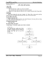
Figure 3-11 illustrates the sequence of these operations.
3-16
Figure 3-11. Basic Batch Plant Operations Shown
(A) in flow chart form and (B) schematically
3-17
Aggregates are removed from storage or stockpiles in controlled amounts
and passed through a dryer to be dried and heated. The aggregates then pass
over a screening unit that separates the material into different sized fractions
and deposits the aggregates for hot storage. The aggregates and mineral
filler (when used) are then withdrawn in controlled amounts, combined with
binder, and thoroughly mixed in a batch. The HMA is loaded directly into
trucks or placed in a surge bin, and hauled to the paving site.
Figure 3-12 illustrates the major components of a typical batch plant. Each
component or group of related components is discussed in detail in sections
that follow; however, an overview of the processes required in plant
operations helps the Technician to understand the functions and relationships
of the various plant components.
Cold (unheated) aggregates stored in the cold bins (1) are proportioned by
cold-feed gates (2) on to a belt conveyor or bucket elevator (3), which
delivers the aggregates to the dryer (4), the aggregate is dried and heated.
Dust collectors (5) remove undesirable amounts of dust from the dryer
exhaust. Remaining exhaust gases are eliminated through the plant exhaust
stack (6). The dried and heated aggregates are delivered by hot elevator (7)
to the screening unit (8), which separates the material into different sized
fractions and deposits the aggregates into separate hot bins (9) for temporary
storage. When needed, the heated aggregates are measured in controlled
amounts in to the weigh box (10). The aggregates are then dumped into the
mixing chamber or pugmill (11), along with the proper amount of mineral
filler, if needed, from the mineral filler storage (12). Heated binder from the
hot binder storage tank (13) is pumped into the binder weigh bucket (14)
which weighs the binder prior to delivery into the mixing chamber or
pugmill where the binder is combined thoroughly with the aggregates. From
the mixing chamber, the HMA is deposited into a waiting truck or delivered
by conveyor into a surge bin.
3-18
Figure 3-12. Major Batch Plant Components
(Many plants also include a baghouse in addition to the
dust collector shown in number 5 above.)
3-19
AGGREGATE COLD FEED
The handling, storage, and cold feed of aggregates in a batch plant is similar
to that in other types of plants. Particular to batch plants are: (1) uniform
cold feed, (2) proportioning of cold aggregates, (3) types of feeders and
controls, and (4) cold-feed inspection.
Uniform Cold Feed
Fine and coarse aggregates of different sizes are placed into separate cold
bins (Figure 3-13). The bins are required to be kept sufficiently full at all
times to ensure there is enough material for a uniform flow through the
feeder. Uniform cold feeding is necessary for several reasons. Among them
are:
1)
Erratic feeding from the cold bins may cause some of the hot
bins to overfill while others may be low on materials
2)
Wide variations in the quantity of a specific aggregate at the
cold feed (particularly in the fine aggregate) may cause
considerable change in temperature of the aggregates leaving
the dryer
3)
Excessive cold feed may overload the dryer or the screens
4)
Wide variations may affect moisture content in the HMA
Figure 3-13. Cold Feed System
3-20
All of these problems contribute to non-uniform HMA at the plant that in
turn causes problems with the pavement. Therefore, controlling the cold
feed is the key to all subsequent operations.
Proportioning of Cold Aggregates
Accurate proportioning of cold aggregates is important because, except for
the small amount of degradation that may occur during drying and screening,
the aggregate gradation in the hot bins is dependent on the cold feed. To
ensure that the hot bins remain in balance, (i.e., contain the correct
proportions of different sized aggregate to produce the desired HMA
gradation), the proportions of aggregates leaving the cold bins are required to
be carefully monitored and controlled.
If the sieve analysis of the cold-feed material indicated any significant
difference from the requirements of the job mix formula, the quantities being
fed by the various cold-feed bins are required to be adjusted to correct the
gradation. This does not require recalibrating the bins. Simply adjusting the
flow rate based on data from the calibration charts corrects the problem.
Type of Feeders and Controls
Aggregate feed units are located beneath the storage bins or stockpiles, or in
positions that assure a uniform flow of aggregate. Feeder units have controls
that may be set to produce a uniform flow of aggregate to the cold elevator
(Figure 3-14).
Figure 3-14. Three Bin Cold Feeder and Belt
3-21
Generally belt and vibratory feeders are best for accurate metering of the fine
aggregates. Coarse aggregates usually flow satisfactorily with any type of
feeder.
For a uniform output from the batch plant, input is required to be accurately
measured. Feeding the exact amounts of each sized aggregate into the dryer
at the correct rate of flow is important.
Inspection of Cold Feed
The Technician is required to observe the gate calibration procedures.
During production, the gate-opening indicators are required to be
periodically checked to ensure that gate openings remain properly set.
The Technician is required to frequently observe the cold feed to detect any
variations in the amount of aggregates being fed. Sluggish feeders may be
caused by material bridging over the gates instead of flowing through.
Sluggish feeders also may be the result of excessive aggregate moisture or
other factors that impede a uniform flow of material to the dryer.
AGGREGATE DRYING AND HEATING
From the cold bins, aggregates are delivered to the dryer. The dryer removes
moisture from the aggregates and raises the aggregate temperature to the
desired level. Basic dryer operation, temperature control, calibration of
temperature indicators, and moisture checks are important.
Dryer Operation
The conventional batch plant dryer is a revolving cylinder ranging from 5 to
10 ft in diameter and 20 to 40 ft in length. The dryer has an oil or gas burner
with a blower fan to provide the primary air for combustion of the fuel, and
an exhaust fan to create a draft through the dryer (Figure 3-15). The drum
also is equipped with longitudinal troughs or channels, called flights that lift
and drop the aggregate in veils through the burner flame and hot gases
(Figure 3-16). The slope of the dryer, rotation speed, diameter, length and
arrangement, and number of flights determine the length of time the
aggregate spends in the dryer.
For efficient dryer operation, the air that is combined with the fuel for
combustion is required to be in balance with the amount of fuel oil being fed
into the burner. The exhaust fan creates the draft of air that carries the heat
through the dryer and removes the moisture. Imbalance among these three
elements causes problems. The lack of sufficient air or excess flow of fuel
oil may lead to incomplete combustion of the fuel. The unburned fuel leaves
an oily coating on the aggregate particles, which may adversely affect the
finished HMA.
3-22
Figure 3-15. Typical Dryer
Figure 3-16. Dryer Flights
A quick procedure to check if oil is coating the aggregate is to place a shovel
full of aggregate being discharged from the dryer in a bucket of water. A
film of oil floats to the surface if there is oil on the aggregate. A slight film
is not of concern; however, a heavy film on the surface of the water requires
immediate attention.
Imbalance between draft air and blower air velocities may cause a back
pressure within the drum. This creates a "puff back" of exhaust at the burner
end of the drum, indicating that draft air velocity is insufficient to
accommodate the air pressure created by the burner blower. In such a case,
either the resistance to draft air is required to be reduced or blower air
pressure decreased.
3-23