On a thermomechanical model of shear instability in machining
Bạn đang xem bản rút gọn của tài liệu. Xem và tải ngay bản đầy đủ của tài liệu tại đây (730.41 KB, 5 trang )
On a Thermomechanical Model of Shear Instability in Machining
Hou Zhen-Bin, Ranga Komanduri (1)
Mechanical and Aerospace Engineering, Oklahoma State University, Stillwater, OK, USA
Received on January 4,1995
ABSTRACT
Shear instability was observed experimentally in machining some of the difficult-tomachine materials, such as hardened alloy steels, titanium alloys, and nickelbase superalbys
yielding cyclic chips. Recht in 1964 developed a classical model of catastrophic shear instability in
machining. In this investigation, based on the analysis of cyclic chip formation in machining,
possible sources of heat (including preheating effects by these heat sources) contributing
toward the temperature rise in the shear band were identified. The temperature rise was
calculated using Jaeger's classical solutions of stationary and moving heat sources. Recht's
original catastrophic shear instability model for shear localization was extended by predicting
analytically the conditions for the onset of shear localization.
Key Words: machining, cutting, shear
"Ioften say that when you can measure what you are
speaking about, and express it in numbers, you know
something about it; but when you cannot measure it,
when you cannot express it numbers, your knowledge is
of a meagre and unsatisfactory kind; it may be the
beginning of knowledge, but you have scarcely, in your
thoughts, advanced to the stage of Science whatever !he
Lord Kelvin
matter may be"
1. INTROOUCTlON
Machining of conventional metals and their alloys,
such as low carbon steels, aluminum alloys, carbon
steels in the practical cutting speed range is characterized by a continuous (Type II) chip [l]. These
materials exhibit high ductility (having a bcc or a fcc
crystal structure) and good thermal properties. There
are, however, other materials, such as titanium alloys,
nickelbase superalloys, hardened alloy steels which
produce cyclic chips when machined due to shear
instability [2-7l. For some of these materials, as in the
case of hardened alloy steels, a transition from a
continuous to a shear localized chip occurs as the cutting
speed is increased 61.However, once the transition from
a continuous to a s ear localized chip occurs, no further
transition or reversal to a continuous chip was observed
with further increase in speed. For other materials, such
as titanium alloys, shear localization seems to occur
throughout the cutting speed range, i.e. from an
extremely low speed to very high speeds. Materials that
tend to form shear localized chips can be characterized
by poor thermal properties and/or limited ductility (as in
the case of materials with a hcp crystal structure).
Shear localization causes cyclic variation of force
(both cutting and thrust) and consequent vibration or
chatter in the metal cutting process. Consequently, an
understanding of the process, the criteria for shear
instability, and the conditions leading to shear localization are im rtant considerations in our quest for
improving pro uctiviiy,
r
part quality, and overall efficiency
of the cutting operation.
F,
2.
CRITERIA FOR SHEAR INSTABILITY
Recht in 1964 [a] developed a classical model of
catastrophic shear instability in machining. Accordingly,
catastrophic shear occurs at a plastically deforming
Annals of the ClRP Vol. 44/1/1995
region within a material when the slope of the true stresstrue strain curve becomes zero, i.e., the local rate of
change of temperature has negative effect on strength
which is equal to or greater than the positive effect of
strain hardening. Assuming an approximate value of the
temperature generated in machining, Recht estimated the
values of thermo-mechanical properties and calculated
the shear strength. In this paper, this model was further
developed based on the experimental results obtained
usin h' h-speed photo raphy, in situ machining inside
an #Elf, and a metahrgical analysis of the chips
generated in conventional machining tests over a range
of cutting speeds. Recht's original thermo-mechanical
model for shear localization in metal cutting was extended
and an attempt was made to predict quantitatively the
conditions for the onset of shear localization. The
temperature raise in the shear band due to the three heat
sources as well as the preheating effects by these heat
sources on the following segment being generated was
calculated. A reasonably ood correlation of the
experimental work with the aniytical modeling was found.
Samiatin and Rao (91 developed another model for
shear localization which incorporates a heat transfer
analysis and materials properties, such as the strainhardening rate, the temperature dependence of the flow
stress and the strain rate sensitivity of the flow stress to
establish the tendency towards localized flow. Using the
data available in the literature, they found the non-uniform
flow in metal cutting is imminent when the ratio of the
normalized flow softening rate to the strain rate
sensitivity is equal to or greater than 5.
In addition to thermo-plastic instability (strain
hardening versus thermal softening) leading to shear
localization, there can be other mechanisms where an
actual reduction in the shear stren th in the shear band
can take place without the therma softening effect. For
example, the generation of microcracks in the shear band
and a reduction in the actual area undergoin stress.
Walker and Shaw [lo] pro sed this for materia s undergoing large shear and omanduri and Brown [ll]
proposed this as a possible mechanism for chip
segmentation in machining. Recent1 , Shaw and Vyas
[12] proposed it for machining an All1 4340 steel at low
cutting speeds. This concept seems to be valid particularly for the case of cyclic chips generated in
machining of titanium alloys at very low speeds. These
B
R"
9
69
speeds are so low that the heat generated in the shear
band could diffuse on either side with the result thermal
softening would be rather difficult. Instead, the actual
shear strength may be lowered by the presence of
microcracks. Other mechanisms proposed for shear
instability include structural transformation, as in the
reversion of marten-site to austenite in some steels [13].
In this paper, only the first mechanism of shear
instability, name1 , thermal softening versus strain
hardening is consdered.
3. PHYSICAL MODEL OF SHEAR LOCALIZATION IN
MACHINING
The followin is the sequence of events leading to
shear-localized clip formation. This model is developed
based on the ex erimental results obtained using highs eed photograpiy, in d u machining inside a scanning
erectron microscope. and metallur ical analysis of the
chips obtained in conventional mac ining tests of these
materials over a range of cutting speeds. There are
basically two stages involved in this process. One stage
involves shear instability and stain localization in a
narrow band in the primary zone ahead of the tool. The
other stage involves u setting of an inclined wed e of
work material by the a ancing tool, with negligible eformation, forming a chip segment. During upsetting of the
segment ahead of the tool in the primary zone, intense
shear takes place at approximately 4!5O to the direction of
cuttin . This occurs not between the chi and the tool
face gut between the last segment an the one. just
formin . Thermo-mechanical response of these drfficultto-mac%ine materials under the conditions of cutting tend
to localize the heat generated due to strain localization
and subsequent shear in a narrow band. Thus, thermal
softening takes place resulting in the shear stress being
lower than that of the bulk material. With increase in
cutting speed, this intense shear takes place so rapidly
that the contact area between any two se ments
gradually decrease to a stage when the in8ividual
segments of the chip are actually separated. Such a
phenomenon was observed at higher cuttin speeds
(above 1,000 m/min) in the case of hardened al oy steels
and nickelbase superalloys.
Figure I (a) to (c) show various stages of shear
localization in machining, Figure 1 (a) shows the inltial
stage where chip segment I has just formed and under the
essure exerted by the tool face on the weakest plane a
Figure 1 (b)], shear S1 commences on the main shear
plane. This high1 intense, narrow shear zone is
designated as ABZD. Note that svgment ll.(i.e. in the
s ment to be deformed) undergoes very little plastic
de ormation. Figure l b shows an intermediate sta e
where the cutting tool has moved a distance
T e
width of the shear zone has increased from AB [Figure 1
(a)] to AC Figure 1 (b)]. Also, the shear zone has rotated
due to pastic indentation (or upsetting) and the
deformation of segment II takes place by the movement
of the cuqing tool. This deformation is caused by the
shear S2 in the weakest plane b of that part of the chip
segment which has its own shear angle @ * and moves
forward together with the cutting tool tip. Figure 1 (c)
shows the final stage where the chip segment I has
sheared along the main shear plane to its maximum
extent and the weakest lane in segment II has reached
its extreme position. Aler that, the weakest plane will
shift to a' as shown in the figure. Thus the next chip
segment is formed. It asain will begin to shear along the
new main shear lane a . At this instant the length of the
shear zone on t e main shear plane of the former chi
segment has its maximum value A'C or ABC [Figure 1 (cf
a
8
8,
s
B
r
7
e.6
I
R
It may be noted that the chip formation process
yielding shear localization is far different from that with a
continuous chip. In the case of a continuous chip, strain
hardening always predominates ove! thermal softening.
Once shear takes place along the main shear plane a, the
stress required for further deformation. is higher than
before, so the weakest lane will be shifted to the next
lane. Thus shear will aso be shifted to the next plane.
his leads to a uniform1 distributed deformation in the
chi s on a macroscale. !r ut in the case of chip formation
wit[ shear localization. thermal softening predominates
over strain hardening. Once shear takes phce along the
?
70
P
main shear plane a, the strength there becomes lower
than before. So, the main shear plane is still the weakest
plane and hence the shear continuous on the same
ane. In other words, shear is localized in a narrow plane.
#
isl results in an inhomogeneous deformation in the
chips on a macroscale. Figure 2 shows ty ical micrographs of a continuous and a shear localize chip at two
different cutting speeds illustrating these features.
4. CRITERION FOR THERMO-MECHANICALSHEAR
INSTABILITY IN MACHINING
8
In this investigation the criterion for shear instability
formulated by Recht in 1964 was further developed by
predicting analytically the conditions for the onset of
shear localization. Based on the analysis of cyclic chip
formation in machining described earlier, possible
sources of heat (including preheatin effects of these
heat sources) in the shear band contrguting towards the
temperature rise were identified. Using Jaeger's classical
solutions for stationary and moving heat sources as
bases (141, the temperature rise in the shear band due to
various heat sources was calculated. Knowing this
temperature, the shear stress in the shear band at the
shear band tem erature was estimated and compared
with the strengtE of the work material at the preheating
temperature. A thermo-mechanical model was developed
wherein if Q' 2 Q, no shear localization takes place but
instead strain hardenin occurs. If Q ' C 6,then shear
localization is imminent. The model proposed redicts the
onset of shear instability (i.e. cutting speed a k v e which
shear localization takes place) reasonably well with the
experimental results reported in the literature [3.6].
5. THERMO-MECHANICALPROPERTIES OF THE
WORK MATERIAL
Based on experimental materials property data
available in the literature on the strain hardening and
thermal softening characteristics, relationships were
developed for the calculation of true stress, Q, in terms of
true strain, E. and temperature, T. Only temperature and
strain effects were considered here as the strain rate
effects could not be considered due to lack of materials
properties data. Similarly, thermal properties of the work
material at different temperatures were obtained from the
literature and used in the analysis.
6. HEAT TRANSFER MODELING
To predict the conditions for the occurrence of
shear localization quantitatively, the tem erature rise in
the shear band during cutting has to
determined.
Based on an analysis of the cyclic chip formation, the
tem erature rise in the shear band is identified as due to
the ollowing three heat sources as well as the preheating
effects of these sources. The three primary heat sources
are: 1 The main shear band heat source, a [see Figure 1
is will be the predominant heat source especially
(b)l;
at igher cutting speeds, (2) the secondary shear band
heat source b [see Figures 1 (b) and (c)]. This is the heat
enerated durin the upsetting stage of cyc!ic chip
krmation, and (38 the frictional heat source, c (Figure 1)
between the s ment already formed and the rake face of
the cutting to? In addition, all the three heat sources
also effect the temperature on the new shear band of the
next chip segment. That is, every new segment, where
shear localization begins to takes place, will occur at a
temperature higher than the room temperature. This is the
preheating effect on the main shear band. Thus, in this
r all the heat sources are identified and used in the
!%ulation
of shear band temperature-rise. It will be
shown later that depending on the cutting speed used,
the influence of some of these heat sources will be more
prominent than others. Some can be neglected at higher
speeds but becomes more significant at lower speeds.
Jaeger's classical instantaneous, infinitely long line heat
source solution is taken as the startin point for all the
three heat sources as well as the t ree preheating
sources. The temperature rise at any point M and at any
instant t due to each of the heat sources is obtained. In
this investigation, temperatures at 15 locations along
the shear band are calculated. The mean of these values
is taken as the temperature rise. The mean temperature
rise in the shear band (Ze)caused by the three heat
sources and that due to three preheating effects are
P
$A
7l
designated as 6.6,&, Q, 6,and %respectively.
Due to limitations of space only the final results are given
here; details of the analytical modeling are given
elsewhere [15].
The first heat source is the main shear band heat
source a [in Figure l(a)]. It is assumed as an infinitely
long, stationary, continuous heat source with a variable
intensity of heat liberation. This heat source includes the
heat generated in the shear band (i.e. between the
segments) and the shear between the segment and the
tool face [see Figures 1 (b) and (c) for details]. The
second heat source is the seconda shear plane heat
source b, caused by the upsetting of #e undeformed part
of the material ahead of the tool face which begins
simultaneously with the be inning of the localized shear
in the main shear band, a !Figure 11. During shear, the
shear plane provides a moving plane heat source with
variable width moving along the direction AB Figure 1 b).
The third heat source, namely, the frictional eat source
between the chi segment already form+ and rake face
of the tool, c. !I is assumed as a moving plane heat
source with variable intensity of heat liberaton. A similar
approach is taken for calculating the temperature rise due
to each of the three preheating sources.
I,
7.
RESULTS AND DISCUSSION
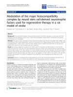
Figures 3 and 4 show the variation of temperature
rise due to various heat sources with cutting speed for an
AlSl 4340 steel and a Titanium 6AI-4V work material,
respectively. They were obtained using the analytical
models proposed earlier. It can be seen that at the low
speeds the temperature rise in the shear band depends
very much on the contributions of the various heat
sources. Also, at the lower speeds, reheating effects
predominate. At the higher speeck however, the
temperature rise due to the first heat source, namely, the
shear band heat source predominates.
Figures 5 and 6 show the variation of shear stress
with cutting speed for an AlSl4340 steel and a Titanium
6AI-4V work material, respectively. 6'is the shear stress
at the shear band temperature and 6 is the shear strength
of the bulk material at the preheating temperature. Except
at very low speeds, 6' decreases (due to thermal
softening effect) while 6 increases (due to decreasing
preheating effect with increasing cutting speed below the
critical speed or shear localization, a' > 6. The
difference between them decreases with increase in
speed. At the critical speed for shear localization, i.e. 6
= b', strain hardening effect equals thermal softening.
Beyond this speed, thermal softening predominates over
strain hardening with the result a'c 6.
It can be seen that the critical speed for shear
localization for Titanium 6A14V is about 8 mlmin while that
for AlSl4340 steel is much higher (about 116 m/min) as
originally predicted by Recht. Also, the ex erimental
results reported earlier for the onset of shear kalization
(namely, 125 mlmin) for AlSl 4340 steel [6] agrees with
the analytical results presented here. However, in the
case of titanium alloys, cyclic chip formation was
observed at speeds much lower than the value reported
here. This difference can be attributed to several factors.
It is possible that the criterion for the onset of shear
localization presented here is somewhat simplistic or
other factors of relevance may not been considered in the
analysis. For exam le, cut thickness may have some
effect in that the preKeatin effects would be different for
a thin chip than a thick c ip. Also, the frictional heat
source (and the preheating effect of this heat source)
between the nascent chip and the tool face during the
indentation of the wedge shaped section of the chip
segment has not been considered in the first
ap roximation. The basic approach and the conclusions
wil still valid. These modifications may move the speed at
which shear localization takes place slightly lower than
what is sreported in this paper.
1
a
P
It is reasonable to assume that at very low cutting
speeds, the conditions in the shear band are far from
adiabatic. Consequent1 , adiabatic (or near adiabatic)
shear instability is unlkely at the very low speeds.
Perhaps, some other mechanism may have to be invoked
to explain for the observed cyclic chip formation at very
low speeds with titanium alloys. It is possible that this
phenomenon is due to a difference in the mechanism of
shear localization from that of a thermal origin to a
mechanical origin, for example, involving microcracks, as
originall proposed by Professor Shaw. This would
effediveyy reduce the stress due to reduced area Work
is under rogress in this direction and it is hoped that the
resutts orit will be communicated soon.
8. CONCLUSIONS
1. In this investigation Recht's catastrophic shear
instabilit model was extended by predicting analytically
the codtions for the onset of shear localization.
2. Based on an analysis of the shear localized chip
formation process, three primary heat sources and
reheating effects of these heat sources were identified.
[sing Jaeger's stationary and moving heat source
solutions the temperature rise in the shear band due to
these heat sources was calculated.
3. Shear stress in the shear band, o', was
calculated at the shear band temperature and compared
with the value of shear strength, 6,at the preheating
tem rature for both AlSl4340 steel and Titanium 6AI4V
worpmaterials. It was found that if 6' c 6, then shear
localiza?ionis imminent. The cutting s eed at which this
occurs is the critical speed for shear kcalization. Shear
localization continues at all speeds above this. Cutting
speed for the onset of shear localization was found to be
much lower for Titanium 6A14V (about 9 m/min) than for
AM4340 steel (130 m/min).
4. Values of a'and 6 were calculated for AlSl4340
steel over a ran e of practical cutting speeds. No shear
localization wasyound up to a speed of about 120 mlmin
with the onset of shear localization above 130 mlmin.
Experimental results reported in the literature agrees
reasonably with the anal tical values. Values of 6'and 6
were also calculated for fitanium 6 AI-4V over a range of
cutting speeds up to 10 m/min. No shear localization was
found up to a speed of about 8 m/min with the onset of
shear localization above 9 m/min.
ACKNOWLEDGMENTS
The authors would like to acknowledge the
continuing support of the National Science Foundation in
the area of manufacturing at OSU. Thanks are due to
Drs. B. M. Kramer, K. Narayanan, W. DeVries, and A.
Hogan of NSF for their interest. Thanks are also due to
many of the collaborators of the Air Force roject on
Advanced Manufacturing which was funded wlen one of
the authors (R.K.) was with G.E. In particular, the many
valuable discussions with Prof. B. F. von Turkovich, Mr.
R. F. Recht, Dr. R. A. Thompson, Dr. M. Lee and Dr. D. G.
Flom are gratefully acknowled ed. Thanks are also due to
some of the graduate stutents who helped in the
reparation of the drawings. Finally, thanks are due to the
OST Chair funds that enabled this work. Thanks are
also due to Prof M. F. DeVries for his review and
comments.
REFERENCES
R4
Merchant, M. E., 1944, Basic Mechanics of the Metal
Cutting Process, Trans ASME, 66: A65-A71
LeMaitre, F., 1970, Contribution a I'etude de I'usinage
du titane et de ses alliages, Annals of CIRP, 23: 413424
Komanduri, R. and B. F. von Turkovich, 1981, New
Observations on the Mechanism of Chip Formation
When Machining Titanium Alloys, Wear, 69: 179-188
Komanduri, R., 1982, Some Clarifications on the
Mechanics of Chip Formation When Machining
Titanium Alloys, Wear, 76:15-34
Komanduri, R. and R. H. Brown, 1981, On the
Mechanics of Chip Segmentation in Machining,
Trans ASME, J of Engg. for Ind. 103 : 33-51
Komanduri, R. and T. A. Schroeder, 1986, On Shear
Instability in Machining a Nickel-Iron Base Superalloy, Trans ASME, J of Engg. for lnd.,108: 93-100
71
[7] Komanduri, R., Schroeder, T. A.. Hazra, J., von
Turkovich, B. F., and D. G Flom, 1982,On the Catastrophic Shear Instability in High-speed Machining of
an AlSl4340 Steel, Trans ASME, J of Engg. for Ind.,
104:121-131
[8] Recht. R. F., 1964, Catastrophic Thermoplastic
Shear, Trans ASME. 86:189-193
[9] Semiatin, S. L. and S. B. Rao. "Shear Localization
During Metal Cutting," Materials Science and
Engineering, fi (1983) 185-192
[lo]Walker, T. J. and M.C. Shaw, 1969.On Deformation
at Large Strains, Proc. of the 10th M.T.D.R.
Conference, 241
[l11 Komanduri, R. and R. H. Brown, 1972,The Formation
of Microcracks in Machining a Low Carbon Steel,
Metals and Materials, 6: 531
(121Shaw, M. C., and A. Vyas, 1993,Chip Formation in
the Machining of Hardened Steel. Annals of CIRP,
42/1: 29-33
[13]Lemaire, J. C. and W. A. Backofen, Feb. 1972,
Adiabatic Instability in the Orthogonal Cutting of
Steel, Metallurgical Trans, 3:477-481
[14]Jaeger, J. C., 1942,Moving Sources of Heat and the
Temperature at the Sliding Contacts, Proc. of the
Royal Society of NSW. 76: 203-224
[15]Hou Zhen-Bin and R. Komanduri, 1995, ThermoMechanical Modelling of Shear Instability in
Machining, Part I:Thermo-mechanical Instability and
Part II. Thermal Analysis, papers to be submitted for
publication
(b)
Figure I(1)to (c) Schematic showing various stages of
shear localization in machining
72
v)
ti
Q,
L
200
150
3
c
9 100
Q,
a
50
5
10
15
20
Cutting Speed, m/min
0
25
Figure 4 Variation of temperature rise due to various heat
sources with cutting speed for Titanium 6AI4V
Z
230
a
Figure 2 (a) and (b) Typical micrographs of a continuous
and a shear localized chip when machining AlSl
4340 steel (Rc 35), at two different cutting
speeds illustrating these features
(a) 125 m/min and (b) 250 m/min [A
........
' . . . I . . . ' , . . . . I , . , .
ze
i
s
220 F '
50
"
'
"
"
"
"
'
"
75
100
125
Cutting Speed, V m/min
' 4
150
Figures 5 Variation of shear stress with cutting speed for
an AlSl4340 steel .
S.L.: shear localization and No S.L. : no shear
localization
140
. ~ ~ . , . ~ ~ . I . . . . I . . , . I . . , ,
.-
y 135 I...........
0
25
50
75
100
Cutting Speed, m/min
125
......................................................
150
Figure 3 Variation of temperature rise due to various heat
sources with cutting speed for an AlSl4340
steel
0
10
15
20
5
Cutting Speed, V m/min
25
Figures 6 Variation of shear stress with cutting speed for
Tiianium 6AI-4V
S.L.: shear localization and No S.L. : no shear
localization
73