System on a chip design and test
Bạn đang xem bản rút gọn của tài liệu. Xem và tải ngay bản đầy đủ của tài liệu tại đây (28.15 MB, 292 trang )
System-on-a-Chip: Design and Test
For a listing of related titles from Artech House,
turn to the back of this book.
System-on-a-Chip: Design and Test
Rochit Rajsuman
Artech House
Boston London
www.artechhouse.com
Library of Congress Cataloging-in-Publication Data
Rajsuman, Rochit.
System-on-a-chip : design and test / Rochit Rajsuman.
p. cm. (Artech House signal processing library)
Includes bibliographical references and index.
ISBN 1-58053-107-5 (alk. paper)
1. Embedded computer systemsDesign and construction.
2. Embedded
computer systemsTesting.
3. Application specific integrated circuitsDesign
and construction.
I. Title.
II. Series.
TK7895.E42 R37 2000
621.395dc21
00-030613
CIP
British Library Cataloguing in Publication Data
Rajsuman, Rochit.
System-on-a-chip : design and test. (Artech House signal processing library)
1. Application specific integrated circuits Design and construction
I. Title
621.395
ISBN 1-58053-471-6
Cover design by Gary Ragaglia
© 2000 Advantest America R&D Center, Inc.
3201 Scott Boulevard
Santa Clara, CA 95054
All rights reserved. Printed and bound in the United States of America. No part of this book
may be reproduced or utilized in any form or by any means, electronic or mechanical, including photocopying, recording, or by any information storage and retrieval system, without permission in writing from the publisher.
All terms mentioned in this book that are known to be trademarks or service marks have
been appropriately capitalized. Artech House cannot attest to the accuracy of this information. Use of a term in this book should not be regarded as affecting the validity of any trademark or service mark.
International Standard Book Number: 1-58053-107-5
Library of Congress Catalog Card Number: 00-030613
10 9 8 7 6 5 4 3 2 1
Contents
Preface
xi
Acknowledgment
xiii
Part I: Design
1
1
Introduction
3
1.1
1.2
1.3
1.3.1
1.3.2
1.4
1.4.1
1.4.2
1.4.3
Architecture of the Present-Day SoC
Design Issues of SoC
HardwareSoftware Codesign
Codesign Flow
Codesign Tools
Core Libraries, EDA Tools, and Web Pointers
Core Libraries
EDA Tools and Vendors
Web Pointers
References
5
8
14
15
18
21
21
23
28
29
2
Design Methodology for Logic Cores
33
2.1
2.2
SoC Design Flow
General Guidelines for Design Reuse
34
36
v
vi
System-on-a-Chip: Design and Test
2.2.1
2.2.2
2.2.3
2.2.4
2.2.5
2.2.6
2.2.7
2.3
2.3.1
2.3.2
2.3.3
2.3.4
2.4
2.4.1
2.4.2
2.5
2.5.1
2.5.2
2.5.3
2.6
2.6.1
2.6.2
2.6.3
Synchronous Design
Memory and Mixed-Signal Design
On-Chip Buses
Clock Distribution
Clear/Set/Reset Signals
Physical Design
Deliverable Models
Design Process for Soft and Firm Cores
Design Flow
Development Process for Soft/Firm Cores
RTL Guidelines
Soft/Firm Cores Productization
Design Process for Hard Cores
Unique Design Issues in Hard Cores
Development Process for Hard Cores
Sign-Off Checklist and Deliverables
Sign-Off Checklist
Soft Core Deliverables
Hard Core Deliverables
System Integration
Designing With Hard Cores
Designing With Soft Cores
System Verification
References
36
36
38
39
40
40
42
43
43
45
46
47
47
47
49
51
51
52
53
53
53
54
54
55
3
Design Methodology for Memory and Analog Cores
57
3.1
3.2
3.2.1
3.2.2
3.2.3
3.3
3.3.1
3.3.2
3.3.3.
Why Large Embedded Memories
Design Methodology for Embedded Memories
Circuit Techniques
Memory Compiler
Simulation Models
Specifications of Analog Circuits
Analog-to-Digital Converter
Digital-to-Analog Converter
Phase-Locked Loops
57
59
61
66
70
72
72
75
78
Contents
vii
3.4
3.4.1
3.4.2
3.4.3
High-Speed Circuits
Rambus ASIC Cell
IEEE 1394 Serial Bus (Firewire) PHY Layer
High-Speed I/O
References
79
79
80
81
81
4
Design Validation
85
4.1
4.1.1
4.1.2
4.1.3
4.2
4.2.1
4.2.2
4.3
4.3.1
4.3.2
4.3.3
Core-Level Validation
Core Validation Plan
Testbenches
Core-Level Timing Verification
Core Interface Verification
Protocol Verification
Gate-Level Simulation
SoC Design Validation
Cosimulation
Emulation
Hardware Prototypes
Reference
86
86
88
90
93
94
95
95
97
101
101
103
5
Core and SoC Design Examples
105
5.1
5.1.1
5.1.2
5.2
5.3
5.4
5.4.1
5.4.2
Microprocessor Cores
V830R/AV Superscaler RISC Core
Design of PowerPC 603e G2 Core
Comments on Memory Core Generators
Core Integration and On-Chip Bus
Examples of SoC
Media Processors
Testability of Set-Top Box SoC
References
105
109
110
112
113
115
116
121
122
Part II: Test
123
6
Testing of Digital Logic Cores
125
6.1
SoC Test Issues
126
viii
System-on-a-Chip: Design and Test
6.2
6.3
6.3.1
6.3.2
6.3.3
6.4
6.5
6.5.1
6.5.2
6.6
6.6.1
6.6.2
6.6.3
Access, Control, and Isolation
IEEE P1500 Effort
Cores Without Boundary Scan
Core Test Language
Cores With Boundary Scan
Core Test and IP Protection
Test Methodology for Design Reuse
Guidelines for Core Testability
High-Level Test Synthesis
Testing of Microprocessor Cores
Built-in Self-Test Method
Example: Testability Features of ARM Processor Core
Debug Support for Microprocessor Cores
References
128
129
132
135
135
138
142
142
143
144
144
147
150
152
7
Testing of Embedded Memories
155
7.1
7.1.1
7.1.2
7.1.3
7.1.4
7.1.5
7.1.6
7.2
7.2.1
7.2.2
7.2.3
7.2.4
7.2.5
7.2.6
7.3
7.3.1
Memory Fault Models and Test Algorithms
Fault Models
Test Algorithms
Effectiveness of Test Algorithms
Modification With Multiple Data Background
Modification for Multiport Memories
Algorithm for Double-Buffered Memories
Test Methods for Embedded Memories
Testing Through ASIC Functional Test
Test Application by Direct Access
Test Application by Scan or Collar Register
Memory Built-in Self-Test
Testing by On-Chip Microprocessor
Summary of Test Methods for Embedded Memories
Memory Redundancy and Repair
Hard Repair
156
156
157
160
161
161
161
162
163
164
164
164
169
171
171
171
7.3.2
7.4
Soft Repair
Error Detection and Correction Codes
175
175
Contents
ix
7.5
Production Testing of SoC With Large Embedded
Memory
References
176
177
8
Testing of Analog and Mixed-Signal Cores
181
8.1
8.1.1
8.1.2
8.1.3
8.2
Analog Parameters and Characterization
Digital-to-Analog Converter
Analog-to-Digital Converter
Phase-Locked Loop
Design-for-Test and Built-in Self-Test Methods for
Analog Cores
Fluence Technologys Analog BIST
LogicVisions Analog BIST
Testing by On-Chip Microprocessor
IEEE P1149.4
Testing of Specific Analog Circuits
Rambus ASIC Cell
Testing of 1394 Serial Bus/Firewire
References
182
182
184
188
191
192
192
195
197
200
200
201
204
9
Iddq Testing
207
9.1
9.1.1
9.1.2
9.1.3
9.1.4
9.2
9.3
9.4
9.5
Physical Defects
Bridging (Shorts)
Gate-Oxide Defects
Open (Breaks)
Effectiveness of Iddq Testing
Iddq Testing Difficulties in SoC
Design-for-Iddq-Testing
Design Rules for Iddq Testing
Iddq Test Vector Generation
References
207
208
212
213
215
218
224
228
230
234
10
Production Testing
239
10.1
Production Test Flow
239
8.2.1
8.2.2
8.2.3
8.2.4
8.3
8.3.1
8.3.2
x
System-on-a-Chip: Design and Test
10.2
10.2.1
10.2.2
10.2.3
10.3
10.3.1
10.3.2
10.3.3
At-Speed Testing
RTD and Dead Cycles
Fly-By
Speed Binning
Production Throughput and Material Handling
Test Logistics
Tester Setup
Multi-DUT Testing
References
241
241
243
245
246
246
247
248
249
11
Summary and Conclusions
251
11.1
11.2
Summary
Future Scenarios
251
254
Appendix: RTL Guidelines for Design Reuse
257
Naming Convention
General Coding Guidelines
RTL Development for Synthesis
RTL Checks
257
258
260
262
About the Author
265
Index
267
A.1
A.2
A.3
A.4
Preface
This project started as an interim report. The purpose was to communicate
to various groups within Advantest about the main issues for system-on-achip (SoC) design and testing and the common industrial practices. Over
one years time, a number of people contributed in various capacities to complete this report.
During this period, I also participated in the Virtual Socket Interface
(VSI) Alliances effort to develop various specification documents related
to SoC design and testing and in the IEEE P1500 working groups effort
to develop a standard for core testing. As a result of this participation, I
noticed that SoC information is widely scattered and many misconceptions
are spread throughout the community, from misnamed terms to complete
conceptual misunderstanding. It was obvious that our interim report would
be quite useful for the community as a general publication.
With that thought, I contacted Artech House. The editorial staff at
Artech House had already been hearing and reading a lot about system-ona-chip and was very excited about this project. Considering the rapid technology changes, a four-month schedule was prepared and I set out to prepare
the manuscript before the end of 1999. Although I had the baseline material
in the form of an interim report, simple editing was not enough. Besides the
removal of some sections from the report, many sections and even chapters
required a complete overhaul and new write-ups. Similarly, a couple of new
chapters were needed. Because of the very aggressive schedule and other
internal projects, at times it felt very tedious and tiring. This may have
resulted in incomplete discussions in a few sections. I was able to fix
xi
xii
System-on-a-Chip: Design and Test
descriptions in some sections based on feedback from my colleagues at ARD
and from Artech reviewers, but readers may find a few more holes in the text.
The objective of this book is to provide an overview on the present state
of design and testing technology for SoC. I have attempted to capture the
basic issues regarding SoC design and testing. General VLSI design and testing discussions are intentionally avoided and items described are specific to
SoC. SoC is in its early stages and so by no means is the knowledge captured
in this book complete. The book is organized into two self-contained parts:
(1) design and (2) testing.
As part of the introduction to Part I: Design, the background of SoC
and definitions of associated terms are given. The introduction also contains
a discussion of SoC design difficulties. Hardwaresoftware codesign, design
reuse, and cores are the essential components of SoC; hence, in Chapter 2,
these topics are discussed, from product definition (specifications) to deliverable requirements and system integration points of view. Some of these
methods are already in use by a few companies, while others are under
evaluation by other companies and standards organizations. For design reuse,
a strict set of RTL rules and guidelines is necessary. Appendix A includes
reference guidelines for RTL coding as well as Lint-based checks for the
violations of these rules.
Whereas Chapter 2 is limited to digital logic cores, Chapter 3 describes
the advantages and issues associated with using large embedded memories on
chips and the design of memory cores using memory compilers. Chapter 3
also provides the specifications of some commonly used analog/mixed-signal
cores such as DAC, ADC, and PLLs. Chapter 4 covers design validation at
individual cores as well as at the SoC level. This chapter also provides guidelines to develop testbenches at cores and SoC levels. Part I concludes with
Chapter 5, which gives examples of cores, core connectivity, and SoC.
As part of the introduction to Part II, a discussion on testing difficulties is given. One major component of SoC is digital logic cores; hence, in
Chapter 6, test methodologies for embedded digital logic cores are described.
Similar to the design methods for digital logic cores, some of the test methods are already in use by a few companies, while others are under evaluation
by other companies and standards organizations. Chapter 6 also provides
the test methods for microprocessor and microcontroller cores. These cores
can be viewed as digital logic cores, howeverbecause of their architecture
and functionalitythese cores are the brains of SoC. Subsequently, few
items beyond the general logic cores are specific to microprocessor/microcontroller cores. These items are also described in Chapter 6.
Preface
xiii
In addition to logic cores, large memory blocks are another major component of SoC. Chapter 7 discusses the testing of embedded memories. Testing of embedded analog and mixed-signal circuits is discussed in Chapter 8.
Iddq testing has continuously drawn attention. Besides the discussion
on technology-related issues, Iddq testing on SoC has some other unique
issues. These issues are discussed in Chapter 9 with design-for-Iddqability
and vector generation methods.
A number of other topics that are important for SoC testing are related
to its manufacturing environment and production testing of SoC. These
items include issues such as at-speed testing, test logistics on multiple testers,
and general issues of the production line such as material handling, speed
binning, and production flow. Discussion on these topics takes place in
Chapter 10. Finally, concluding remarks are given in Chapter 11.
Acknowledgment
First of all, I want to express my thanks to the editorial staff at Artech House
for their prompt response, enthusiasm, energetic work, and wonderful treatment. My special thanks are due to Mark Walsh, Barbara Lovenvirth,
Jessica McBride, Tina Kolb, Bridget Maddalena, Sean Flannagan, and Lynda
Fishbourne. I am also thankful to Artechs reviewers for reading the draft and
providing very valuable comments.
Needless to say, I am thankful to the many people at ARD who helped
me in one way or another with this work. Without continuous support and
encouragement from Shigeru Sugamori, Hiro Yamoto, and Robert Sauer,
this book would not have materialized. I specifically want to express my
thanks to Robert Sauer for the generous amounts of time he spent reviewing
chapter drafts during evenings and weekends and giving me feedback. This
help was invaluable in identifying many mistakes and omissions. His feedback together with Artechs reviewers helped me resolve many deficiencies in
the text.
I also acknowledge and express my thanks to the design and test
community in general for their work, without which no book can be written.
Specifically, I want to acknowledge the VSI Alliance for developing various
specification documents for SoC design and testing. The ongoing work
by the IEEE P1500 Working Group as well as publications by the IEEE
and Computer Society Press are gratefully acknowledged. I am also thankful to
the IEEE for their permission to use numerous diagrams from various papers.
This Page Intentionally Left Blank
Part I:
Design
This Page Intentionally Left Blank
1
Introduction
In the mid-1990s, ASIC technology evolved from a chip-set philosophy to
an embedded-coresbased system-on-a-chip (SoC) concept. In simple terms,
we define an SoC as an IC, designed by stitching together multiple stand-alone
VLSI designs to provide full functionality for an application. This definition of
SoC clearly emphasizes predesigned models of complex functions known as
cores (terms such as intellectual property block, virtual components, and
macros are also used) that serve a variety of applications. In SoC, an ASIC
vendor may use a library of cores designed in-house as well as some cores
from fabless/chipless design houses also known as intellectual property (IP)
companies. The scenario for SoC design today is primarily characterized by
three forms [1]:
1. ASIC vendor design: This refers to the design in which all the components in the chip are designed as well as fabricated by an ASIC
vendor.
2. Integrated design: This refers to a design by an ASIC vendor in
which all components are not designed by that vendor. It implies
the use of one or multiple cores obtained from some other source
such as a core/IP vendor or a foundry. The fabrication of these
designs is done by either the ASIC vendor or a foundry company.
3. Desktop design: This refers to the design by a fabless company that
uses cores which for the most part have been obtained from other
3
4
System-on-a-Chip: Design and Test
sources such as IP companies, EDA companies, design services
companies, or a foundry. In the majority of cases, an independent
foundry company fabricates these designs.
Because of the increasing integration of cores and the use of embedded
software in SoC, the design complexity of SoC has increased dramatically
and is expected to increase continuously at a very fast rate. Conceptually this
trend is shown in Figure 1.1.
Every three years, silicon complexity quadruples following Moores
law. This complexity accounts for the increasing size of cores and the shrinking geometry that makes it necessary to include more and more parameters in
the design criterion. For example, a few years ago it was sufficient to consider
functionality, delay, power, and testability. Today, it is becoming increasingly important to also consider signal integrity, electromigration, packaging
effects, electomagnetic coupling, and RF analysis.
In addition to the increasing silicon IP complexity, the embedded software content has increased at a rate much higher than that of Moores law.
Hence, on the same scale, overall system complexity has a much steeper slope
than that of silicon complexity.
Complexity
Si cores and mega-functions
Embedded Software
Glue Logic
o
mc
e
yst
S
1995
Si
y
xit
re
a
ftw
o
ds
e
dd
be
Em
xity
le
mp
le
mp
co
ity
plex
om
IP c
2000
Figure 1.1 Trend toward increasing design complexity due to integration.
Introduction
5
1.1 Architecture of the Present-Day SoC
In all SoC designs, predesigned cores are the essential components. A system
chip may contain combinations of cores for on-chip functions such as microprocessors, large memory arrays, audio and video controllers, modems, Internet tuner, 2D and 3D graphics controllers, DSP functions, and so on. These
cores are generally available in either synthesizable high-level description language (HDL) form such as in Verilog/VHDL, or optimized transistor-level
layout such as GDSII. The flexibility in the use of cores also depends on the
form in which they are available. Subsequently, soft, firm, and hard cores are
defined as follows [13]:
• Soft cores: These are reusable blocks in the form of a synthesizable
RTL description or a netlist of generic library elements. This implies
that the user of soft core (macro) is responsible for the actual implementation and layout.
• Firm cores: These are reusable blocks that have been structurally and
topologically optimized for performance and area through floor
planning and placement, perhaps using a range of process technologies. These exist as synthesized code or as a netlist of generic library
elements.
• Hard cores: These are reusable blocks that have been optimized for
performance, power, and size, and mapped to a specific process
technology. These exist as a fully placed and routed netlist and as a
fixed layout such as in GDSII format.
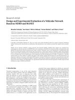
The trade-off among hard, firm, and soft cores is in terms of parameters such as reusability, flexibility, portability, optimized performance, cost,
and time-to-market. Qualitatively, this trade-off is shown in Figure 1.2.
The examples of core-based SoC include todays high-end
microprocessors, media processors, GPS controllers, single-chip cellular
phones, GSM phones, smart pager ASICs, and even PC-on-a-chip. Note
that some people do not consider microprocessors within the definition of
SoC; however, the architecture and design complexity of microprocessors
such as the Alpha 21264, PowerPC, and Pentium III is no less than that of
SoC by any measurement.
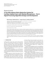
To understand the general architecture of SoC, Figure 1.3 shows an
example of high-end microprocessors, and Figure 1.4 illustrates two SoC
designs. Both figures show the nature of components used in todays SoC.
6
System-on-a-Chip: Design and Test
Soft
core
Re-usability
Portability
Flexibility
Firm
core
Hard
core
Higher predictability, performance, short SoC time-to-market
Higher cost and effort by the IP vendor
Figure 1.2 Trade-offs among soft, firm, and hard cores.
Bus
control
Floatingpoint
control
Paging with
translation
look-aside buffer
Integer
RISC core
Floatingpoint
multiplier
Threedimensional
graphics
Floatingpoint
adder
Floatingpoint
registers
Clock
Instruction
cache
Data
cache
Figure 1.3 Intels i860 microprocessor. (From [4], © IEEE 1989. Reproduced with
permission.)
Introduction
7
Decimator
and FIFO
DSP
coreDAU
SIO PIO
Interpolator, FIFO,
and digital ∆ΣM
Analog A/D and D/A
DSP core
ROM
ROM ROM
RAM
RAM
RAM
RAM
ROM ROM
ROM
(a)
(b)
Figure 1.4 Examples of todays SoC: (a) Codec sign processor. (From [5], © IEEE 1996.
Reprinted with permission.) (b) MPEG2 video coding/decoding. (From [6],
© IEEE 1997. Reproduced with permission.)
Based on these examples, a generalized structure of SoC can be shown as
given in Figure 1.5.
PLL
Memory
Memory
TAP
Microprocessor
core
Glue logic
Memory
Function
specific
core A
Function
specific
core B
PCI
Memory
Function
specific
core C
A/D, D/A
Figure 1.5 General architecture of todays embedded core-based system-on-a-chip.
8
System-on-a-Chip: Design and Test
Figures 1.3 to 1.5 illustrate examples of common components in
todays SoC: multiple SRAM/DRAM, CAM, ROM, and flash memory
blocks; on-chip microprocessor/microcontroller; PLL; sigma/delta and
ADC/DAC functional blocks; function-specific cores such as DSP; 2D/3D
graphics; and interface cores such as PCI, USB, and UART.
1.2 Design Issues of SoC
Due to the use of various hard, firm, and soft cores from multiple vendors,
the SoC design may contain a very high level of integration complexity,
interfacing and synchronization issues, data management issues, design verification, and test, architectural, and system-level issues. Further, the use of a
wide variety of logic, memory, and analog/mixed-signal cores from different
vendors can cause a wide range of problems in the design of SoC. In a recent
survey by VLSI Research Inc., the following design issues were identified [7]:
Portability Methodology
• Non-netlisted cores;
• Layout-dependent step sizes;
• Aspect ratio misfits;
• Hand-crafted layout.
Timing Issues
• Clock redistribution;
• Hard core width and spacing disparities;
• Antenna rules disparities;
• RC parasitics due to chip layers;
• Timing reverification;
• Circuit timing.
Processing and Starting Material Difficulties
• Non-industry-standard process characteristics;
• N-well substrate connections;
Introduction
9
• Substrate starting materials;
• Differences in layers between porting and target process.
Other Difficulties
• Mixed-signal designs are not portable;
• Accuracy aberrations in analog;
• Power consumption.
To address such a wide range of difficulties, a number of consortiums
have developed (or are developing) guidelines for the design of cores and how
to use them in SoC. Some notable efforts are:
• Pinnacles Component Information Standards (PCIS) by Reusable
Application-Specific Intellectual Property Developers (RAPID)
[8, 9];
• Electronic Component Information Exchange (ECIX) program by
Silicon Integration Initiative (Si2) [10, 11]; and
• Embedded core design and test specifications by Virtual Socket
Interface (VSI) Alliance [1216].
The VSI Alliance has also developed an architecture document and
specifications for an on-chip bus [12, 13]. The objectives of the architecture
and on-chip bus (OCB) specifications are to accelerate the mix-and-match
capabilities of cores. That is, in an SoC design with almost any on-chip bus,
almost any virtual component interface (VCI) compliant core can be integrated. The conceptual view of a VSI OCB-based SoC design is illustrated in
Figure 1.6 [13].
Conceptually, Figure 1.6 is similar to 1980s system design with a fixed
interface such as an RS232, USB, or PCI bus. From a system design point of
view, the components that support a common interface can be plugged into
the system without significant problems using a fixed data transfer protocol.
Many companies have proposed proprietary bus-based architectures to
facilitate core-based SoC design. Examples are IBM core-connect, Motorola
IP-bus under M-Core methodology, ARMs advanced microcontroller bus
architecture (AMBA), and advanced high-performance bus (AHB). The reason for this emphasis on OCB is that it permits extreme flexibility in core
10
System-on-a-Chip: Design and Test
Bus wrappers
CPU
MMU
VC interface
Bus I/F
Cache
Processor OCB
VC cores
Host OCB VCs
VC cores
CPU
bridge
Arbiter
System OCB
Peripheral OCB VCs
VC cores
OCB
bridge
Peripheral
OCB
Figure 1.6 VSI hierarchical bus architecture for SoC design. (From [13], © VSIA 1998.
Reproduced with permission.)
connectivity to OCBs by utilizing a fixed common interface across all cores.
This architecture allows data and instruction flow from core-to-core and
core-to-peripherals over on-chip buses. This is very similar to chip-to-chip
communication in computers in the 1980s.
In terms of task responsibilities in SoC design, VSI defines its specifications as bridges between core provider and core integrator. An overview of
this philosophy is illustrated in Figure 1.7 [3].
Most of the ASIC and EDA companies define flowcharts for design
creation and standardize in-house design methodology based on that, from
core design sign-off to SoC design sign-off. For example, IBMs Blue Book
methodology and LSI Logics Green Book methodologies are widely known.
The web sites of most ASIC companies contain an overview of reuse/corebased design methodology and the specification of cores in their portfolio.
Traditionally, the front-end design of ICs begins with system definition in behavioral or algorithmic form and ends with floor planning, while
the back-end design is defined from placement/routing through layout
release (tape-out). Thus, the front-end design engineers do not know much
about the back-end design process and vice versa. For effective SoC design,
vertically integrated design engineers are necessary who have full responsibility for a block from system design specifications to physical design prior
to chip-level integration. Such vertical integration is necessary for functional