HYUNDAI AERO TOWN D6DA 2010 hệ THỐNG PHANH ANTI LOCK BRACKE general
Bạn đang xem bản rút gọn của tài liệu. Xem và tải ngay bản đầy đủ của tài liệu tại đây (367.38 KB, 17 trang )
General
ABS Function
Under rapid braking or sloppy road condition by rain or snow, braking a vehicle in running is apt
to generate skid condition. The skid may decrease braking force to increase braking distance,
generate spin by traverse slipping, and/or disable steering control, resulting to an accident.
Therefore the ABS system is designed to prevent from wheel locking and slip upon braking for
ensuring :
1 Stability,
.
2.Steer ability, and
3 Optimum braking power and stopping distance.
. Skid : A vehicle may slip to move without wheel rotation upon braking.
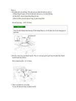
Slip rate (λ)
Upon braking a vehicle which is running, slip rate changes from 0 to 100% until the wheels are
locked and the vehicle stops completely. The slip rate l may be indicated as the below :
λ = Vehicle speed - Wheel speed / Vehicle speed × 100(%)
The slip rate (λ) and the surface friction coefficient (μB) may be correlated as the illustration.
The slip rate (λ) at the max.mB differs by the road condition but the max. range is approx,
8~30%. The cornering force (transversely slip preventing force) decreases with increasing slip
rate. Once wheels are locked, surface friction coefficient μB decreases and slip friction
coefficient μS becomes to '0', and then wheels are easy to slip.
In fact locked rear wheels generate spinning and locked front wheels disables steer ability. The
ABS system controls braking force to maintain the slip rate in the range of 8~30%, in order to
generate max. surface friction coefficient, control slip friction coefficient at higher range, and
provide stability and steer ability.
ABS Effect
The ABS system provides stable braking under extreme condition. Even braking rapidly on
frozen or snowy road, wheels are not locked and maintain max. friction with the road surface to
provide optimum braking distance. Restricting the pressure in the chamber locked at the wheel
side on the road surface, the system ensures straight forward motion. The driver may acquire
correct alignment of the vehicle by adjusting the steering wheel only a little.
ABS configuration
Full air brake
Air over hydraulic brake
Principle
Parts functions
1 Wheel speed sensor
. The 4-channel ABS uses four wheel speed sensors. The sensor consists of a permanent magnet
connected to metal rod, around which a coil has been wound. A pulse wheel mounted to the
hub induces an alternating voltage in the sensor coil. The frequency of the alternating voltage
is managed signal in the control unit.
2.ABS/ASR control unit
The ABS/ASR control unit is designed in digital type and possess dual microprocessors, with
the following four features:
(1)Input stage
The unit checks the wheel speed signal
(2)Computer
The computer calculates the brake slip/traction and wheel deceleration/wheel acceleration
control signal, and energize the output stage when wheels are about to be locked or spin.
(3)Output stage
The unit energizes interface and axle weight distribution unit for controlling the pressure
control valve, the solenoid valve, and the engine.
(4)Power supply
The unit supplies stable voltage for the control unit operation. The built-in protective
device prevents electrical interference from applying to the vehicle electrical circuit.
3 Pressure control valve (1 channel)
. Each wheel is not controlled by a 1 channel control valve. The pressure control valve includes
two diaphragm type valves (for pressure modulation, and for outlet) that are guided and
controlled by the solenoid valves. Upon normal braking, compressed air freely pass through the
pressure control valve to the brake cylinder. If one of wheels is about to be locked, the
ABS/ASR control unit energizes both solenoid valves to lower the pressure in the brake
cylinder. The pressure modulation valve operates to modulate the pressure. When the pressure
is rising no current flows in the two solenoid valves.
4.Solenoid valve
The solenoid valves are connected with two 3/2 solenoid valves that are pilot-controlled. When
wheel's are about to spin, the valve energizes the axle brake cylinder driven by compressed air.
Two control plungers are controlled by the solenoid valves.
When current is interrupted, power supply 1 is close and the cylinder connections are open
outwards.
ABS control
When the drive press the brake pedal, the pressure is supplied to the brake cylinder (or air
chamber), and result to wheel deceleration. When the brake slip is lower than the ABS system
reaction limit value, the braking power is not controlled. The ABS/ASR valve rises. In order to
provide the most proper pressure in the brake cylinder, the pressure decreases, is maintained, or
increases in accordance with friction coefficient between tires, road surface, and vehicle steering.
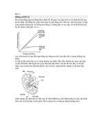
The illustration 6 indicates the ABS control feature on wheels upon braking. At time t1, the
pressure in the brake cylinder increases and the wheel speed decreases. At time t2, the wheel
deceleration and the slip rate increase above the limit, and the wheel is about to be locked. With
closing the pressure modulation valve and opening the exhaust valve, the pressure in the brake
cylinder increases until the wheel speed increases again at time t3. Closing the exhaust valve, the
pressure is maintained at a certain level to time t4. Then the slip value l =0 approximately, and
the wheel acceleration reached the value that may raise the pressure again. Then instantly
opening and closing the pressure modulation valve, the pressure becomes pulse-up until time t5.
The wheel deceleration and slip is higher than the limit again, and the pressure rise again. The
control cycle repeats until the vehicle stops actually.
Yaw moment on the front axle
When the friction coefficients are significantly different between right and left wheels (for
example when the road is frozen at outer side), corrective control feature is applied to the front
axle accommodating between short braking distance and steering corrective value. Constraining
pressure rising and braking force on wheels, the yaw moment is restricted within the range that
vehicle control is possible under rapid braking condition.
Friction force between tire and surface
Friction force between tires and road surface when other conditions are same, friction forces
between tires and road surfaces are virtually same for starting and braking conditions. Friction
force measurement (friction coefficient) differs by road condition, weather condition, tread type,
and especially braking and wheel slip. (Refer to illustration 7). In usual, braking motive force is
within the stable area of slip curve. In general rapid braking increases brake slip and decrease
friction force. With higher brake slip, wheels have lower traverse force for stability and steer
ability of the vehicle.
The ABS system is designed primarily for stability and steer ability of the vehicle. Friction force
on running as well as on braking relies particularly on slip between tires and road surfaces. With
higher wheel slip, traction and running stability decreases. With lowest wheel friction,
differential function provides driving power.
performance when there are faults present
Speed sensor
System configuration : Air over hydraulic brake
ABS control
Failure
WL
Front left
Front
right
Front left speed sensor
NO¹
IC
IC
IC
ON
Front right speed sensor
IC
NO¹
IC
IC
ON
Rear left speed sensor
SL
SL
NO
IC
ON
Rear right speed sensor
SL
SL
IC
NO
ON
Mixed up speed sensors
NO
NO
NO
NO
ON
Tire size, alignment error
NO
NO
NO
NO
ON
Two speed sensor errors or one
speed sensor error and one PMV
error
NO
NO
NO
NO
ON
IC : individual control
Rear left Rear right
SL : Select low
WL : Warning lamp
1) Brake pressure is modulated according to behavior of not affected wheel.
System configuration : Full air brake
ABS control
Failure
WL
Front left
Front
right
Front left speed sensor
NO¹
IC¹
IC
IC
ON
Front right speed sensor
IC¹
NO¹
IC
IC
ON
Rear left speed sensor
MIC
MIC
NO
IC
ON
Rear right speed sensor
MIC
MIC
IC
NO
ON
Mixed up speed sensors
NO
NO
NO
NO
ON
Tire size, alignment error
NO
NO
NO
NO
ON
Two speed sensor errors or one
speed sensor error and one PMV
error
NO
NO
NO
NO
ON
Rear left Rear right
IC : individual control
SL : Select low
MIC : Modified individual control
1) MIC if affected wheel is on high m side.
PMV errors
System configuration : Full air brake
ABS control
Failure
WL
Front left
Front
right
Valve solenoid front left shorted
low or broken wire or valve ground
front left broken wire
NO
IC
IC
IC
ON
Valve solenoid front right shorted
IC
NO
IC
IC
ON
Rear left Rear right
low or broken wire or valve ground
front right broken wire
Valve solenoid rear left shorted low
or broken wire or valve ground rear
left broken wire
MIC
MIC
NO
IC
ON
Valve solenoid rear right shorted
low or broken wire or valve ground
rear right broken wire
MIC
MIC
IC
NO
ON
Any valve solenoid or valve ground
shorted high
NO
NO
NO
NO
ON
Valve ground shorted low
MIC
MIC
IC
IC
ON
Two valve error or one valve error
and one speed sensor error
NO
NO
NO
NO
ON
System configuration : Air over hydraulic brake
ABS control
Failure
WL
Front left
Front
right
Valve solenoid front left shorted
low or broken wire or valve ground
front left broken wire
NO
NO
IC
IC
ON
Valve solenoid front right shorted
low or broken wire or valve ground
front right broken wire
SL
SL
NO
IC
ON
Valve solenoid rear right shorted
low or broken wire or valve ground
rear right broken wire
SL
SL
IC
NO
ON
Any valve solenoid or valve ground
shorted high
NO
NO
NO
NO
ON
Valve ground shorted low
SL
SL
IC
IC
ON
Two valve error or one valve error
and one speed sensor error
NO
NO
NO
NO
ON
Rear left Rear right
Power supply errors
ABS control
Failure
Front left
Front
Rear left Rear right
WL
right
GND shorted high or broken wire
NO
NO
NO
NO
ON
U_PMV or U_ECU over voltage or
low voltage¹
NO
NO
NO
NO
ON
U_PMV or U_ECU broken wire
NO
NO
NO
NO
ON
1 : Errors are reversible (can reast) provided they do not occur during ABS cycles.
Miscellaneous errors
ABS control
Failure
WL
Front left
Front
right
NO
NO
NO
NO
ON
Internal relay always ON
YES¹
YES¹
YES¹
YES¹
ON
RET shorted high or shorted low or
broken wire
YES¹
YES¹
YES¹
YES¹
ON
CAN interface bus off
YES¹
YES¹
YES¹
YES¹
ON
CAN interface error on message
ERC1
YES¹
YES¹
YES¹
YES¹
ON
Internal ECU failure or internal
relay switch failure
Safety monitoring
Rear left Rear right
1 Safety monitoring
. The ABS system satisfies highest safety and reliability requirements. Prior to starting the
vehicle, microcomputers perform self-diagnosis and check other computers, and then monitor
wheel spin sensor, pressure modulation valve, wiring harness, and the whole ABS system.
Finding a failure the ABS system becomes wholly or partly inoperable and the warning lamp
comes on. The service brake system is still operable.
2.Self-diagnostic feature
In addition to the safety monitoring system, the self-diagnostic feature built in the ABS control
unit enables to remove the failure immediately and safely. Upon failure detection by the ABS
control unit, the failure code is stored in the computer that may be read later at a service shop.
Then temporary failures including poor contraction at plug connection may be found and
eliminated soonest.
3 How to read the failure code
. Failure codes may be read using a Hi-scan and self-diagnosis by blink signals of the lamp.
Self-diagnosis on a vehicle
1 ABS lamp
. When a problem occurs in using the ABS system, the red ABS lamp comes on for warning in order to
facilitate finding the trouble area by self-diagnosis.
In normal condition, the ABS lamp comes on upon switching the battery power on and extinguished upon
starting the vehicle and during running. If a trouble occurs in the ABS system during running, the ABS lamp
comes on even or running.
2.Diagnostic method
The blink code device reads out error codes of 16 systems that are stored in the ECU system
configuration and error memory. The device checks the brake signal, as well.
The blink codes may be read using the ASR lamp, and troubles read with the self-diagnostic
button may be identified using the blink code table.
3 Blink code configuration
. In order to operate the blink code, keep the self-diagnostic button pressed for two seconds and then release it.
Pressing the button once it will indicate the system configuration and an error code. Press the self-diagnostic
button once again to read error codes.
The ASR lamp indicates an error code each time pressing the button.
After reading out all error codes stored in the memory using the blink codes, the last stored code may be read
continually.
Quitting self-diagnosis for 5minutes or more, or switching the starting key off and on again, the selfdiagnostic feature reads all information again from the beginning, the system configuration.
Each error code including the brake signal failure, includes three blocks.
The first block may be read at 100's digit, the second block at 10's digit, and the third block at 1's digit.
4.Failure memory erasion
Then ABS ECU will erase all error codes when the diagnostic push button is pressed during power on.
5.Safety measure
Upon ABS failure
Failed circuit
Operate as a non-ABS brake
Other circuits
ABS operation
At least the ABS system may operate just same as a non-ABS brake.
Hi-scan check
1 Turn the starting key off.
.
2.Connect a Hi-scan with the data link connector located under the low crash pad panel.
3 Turn the starting key on.
.
4.Using the Hi-scan, check DTCs.
5.Upon repairing or correcting the problem, turn the starting switch and clear stored error codes
using the clear key.
6 Disconnect the Hi-scan.
.