HYUNDAI AERO TOWN D6DA 2010 hệ THỐNG PHANH HT PHANH hơi HOÀN TOÀN installation
Bạn đang xem bản rút gọn của tài liệu. Xem và tải ngay bản đầy đủ của tài liệu tại đây (197.35 KB, 8 trang )
Installation
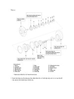
1 Dissamble is the reverse of installation.
.
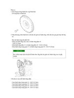
2.Fasten cover 5 to brake spider 1with M8 bolts.
Tightening torque : 20~24Nm.
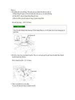
3 Set hold-down springs 8 and so that they are against the brake spider 1, and fasten with screw
. with hexagonal recessed hole M10 and washer.
Tightening torque : 65~75Nm.
The opening of the hold-down spring must face brake shoe.
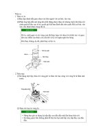
4.Install thrust pieces 7 in brake spider 1.
1. Lubricate thrust pieces before installation.○
The plane surface of the thrust pieces and the brake spider must be nonlubricated
2. The thrust piece with the angled shoe abutment (arrow) must be fitted to the
leading shoe side.
The slope of the abutment must point towards the centre of the brake.
3. The thrust piece with the straight shoe abutment must be fitted to the trailing
shoe.
5.Moisten seat "Z" before installation, point 4.
Set expander unit 2 in the brake spider 1, and fasten with M12 bolts.
Tightening torque : 124~146Nm.
1. The opening of the leaf spring 31 must face to the centre of the brake.
2. Head expander dimension "S" see below illustration.
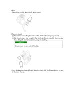
6 Smear the break shoe contact areas ○ of the brake spider with grease.
.
7.place the brake shoes 3 on the brake spider 1, and slide them under the hold-down
springs 8.
1. Before assembly smear the brake shoe contact areas and the shoe webs in the
area of the hold down springs with grease.
8.Fit shoe return springs 4 ensuring they are positioned correctly.
9.Fit the plugs (arrow) in the cover 5 openings.
General remarks
Brakes and brake drums must be maintained in good working conditions to ensure safe
and proper vehicle operation.
It is very important that vehicle manufacturer preventive maintenance schedules be
followed and that wear parts be replaced when needed. The replacement of wear parts is
described in the following sections concretely.
• The replacement of wear parts should be axle-wise, i.e. in both brakes.
• Only use original spare parts from the vehicle manufacturer.
• Repair and service functions to be carried out only by vehicle manufacturer authorized
repair facilities employing trained and qualified personal.
Only common shop tools are necessary for the servicing and repair.
Bedding procedure
A new brake lining must be bedded in carefully in order that optimal brake effectiveness
is attained. During the bedding period when the lining is not fully match with the drum, it
is important to avoid heavy and continuous use of the brakes, particularity from high
speeds, otherwise local overheating the lining and the drum will a consequent detraction
in brake performance.
Other brake parts
All rubber parts are be renewed not later than every 2year. This also applies to the shoe
return and hold-down springs (4,8). Should the springs become damaged, e.g. over
extended, corroded, over heated etc. beforehand, an earlier replacement is necessary.
Replacement
The brake lining must be renewed when its remaining thickness has reached 4,5 mm or
the wear indicator step in the lining, or when they have become burned, glazed of
contaminated with oil.
The visual control should be carried out in defined intervals according to duty levels, the
leading shoe lining has the higher wear rate.
• Only brake lining material which is approved by the vehicle manufacturer may be
used.
• When replacement is necessary then all linings in the brakes or the axle must be used.
Should the drum wear be greater than the lining to drum clearance thus preventing
renewal of the drum, de-adjustment of the brake shoes will be necessary. This is carried
out by engaging a screwdriver, in the toothed wheel 33 via the opening (arrow) in cover 5
and turning the toothed wheel 33 in the clockwise direction until sufficient clearance is
attained.
Upon renewal of the drum the resetting of the adjuster screw 15 can be done by hand.
Remove the upper and lower return spring 4 with a suitable tool (Screwdriver) and
withdraw the shoes from the hold-down spring 8. De-rivet the lining by removing the
preened end of the rivet with a drill tacking care not to enlarge the rivet holes in the shoe.
Clean shoe and ensure it is not damaged or deformed. Fit new linings suitablly to the
shoes.
Before assembly of the brake the new lining should be turned or ground to a diameter of
359,5-1,5 mm by a drum diameter of 360mm, to ensure a correct lining/drum fit and
facilitate the bedding process. By overturning observe the expander unit distance "S" of
158 mm. The thickness of the standard size lining is dimensioned accordingly. If machine
equipment is not available, the thinner service lining should be used.
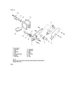
Actuating cylinder replacement
Release lock nut and remove cylinder. Screw lock nut onto new cylinder by at least
27mm, smear cylinder thread with TEROSON-ATMOSIT. Screw the cylinder in to the
thread of the expander unit until abutment and then return so far to obtain the requisite
position of the air connection.
The lowest drainage hole must be open and point as near as possible vertical to the
ground.
It is very important that the lowest hole remains open and the other holes are sealed with
a plug.
Tighten lock nut with a tightening torque 280~320Nm.
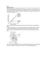
During the assembly of the operation cylinder it has to be generally noted, that the free
end of the wedge, which reaches out of the wedged assembly housing is aligned
according to the housing center A - see illustration and not sloping. if it is sloping it is
possible, that the wedge is not in it's correct position, i.e. the rollers 11are not in contact
with the pistons 12.
To avoid mistakes during the reassembly of the operation cylinder, it is necessary to
follow the work sequences and notes below.
• Align the wedge 9 with the axle A of the wedge assembly housing.
• Push the wedge 9 in this position in the direction of the arrow into the housing 2. The
rollers 11 must point in the direction of the pistons 12.
• It has to be noted, that the rollers with their cage are not allowed to rest on the guide at
the side of the housing.
• Place the rollers carefully between the pistons. The roller cage shall not abut at the
edge of the piston.
It is possible to check the original position of the wedge. With a sight pressure of the
hand rotate the outer end of the wedge. Does it more into the housing, the correct
position was not reached.
Continuing the assembly of the brake system, i.e. fixing of the operation cylinder at the
brake, it must be sure, that the wedge keeps in its original position.
Maintenance and assembly of the expander unit
The adjuster is in principle maintenance free. The expander unit should be inspected for
damage and waer after not more than 2 years in service. Should damage occur
beforehand, or the expander unit or adjuster mechanism fail, then these pats should be
replaced completely.
In any case the rubber parts must be renewed every 2 years.
Damaged rubber parts must be replaced directly.