the american practical navigator chapt 02
Bạn đang xem bản rút gọn của tài liệu. Xem và tải ngay bản đầy đủ của tài liệu tại đây (364.12 KB, 8 trang )
CHAPTER 2
GEODESY AND DATUMS IN NAVIGATION
GEODESY, THE BASIS OF CARTOGRAPHY
200. Definition
Geodesy is the science concerned with the exact
positioning of points on the surface of the Earth. It also
involves the study of variations of the Earth’s gravity, the
application of these variations to exact measurements on
the Earth, and the study of the exact size and shape of the
Earth. These factors were unimportant to early navigators
because of the relative inaccuracy of their methods. The
precision of today’s navigation systems and the global
nature of satellite and other long-range positioning methods
demand a more complete understanding of geodesy by the
navigator than has ever before been required.
201. The Shape of the Earth
The topographic surface is the actual surface of the
earth, upon which geodetic measurements are made. These
measurements are then reduced to the geoid. Marine
navigation measurements are made on the ocean surface
which approximates the geoid.
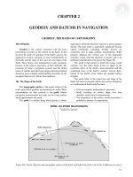
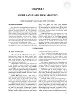
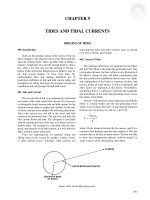
The geoid is a surface along which gravity is always
equal and to which the direction of gravity is always perpendicular. The latter point is particularly significant because
optical instruments containing leveling devices are
commonly used to make geodetic measurements. When
properly adjusted, the vertical axis of the instrument
coincides exactly with the direction of gravity and is by
definition perpendicular to the geoid. See Figure 201.
The geoid is that surface to which the oceans would
conform over the entire Earth if free to adjust to the
combined effect of the Earth’s mass attraction and the
centrifugal force of the Earth’s rotation. Uneven distribution of the Earth’s mass makes the geoidal surface
irregular.
The geoid refers to the actual size and shape of the
Earth, but such an irregular surface has serious limitations
as a mathematical Earth model because:
• It has no complete mathematical expression.
• Small variations in surface shape over time
introduce small errors in measurement.
• The irregularity of the surface would necessitate a
prohibitive amount of computations.
Figure 201. Geoid, ellipsoid, and topographic surface of the Earth, and deflection of the vertical due to differences in mass.
15
16
GEODESY AND DATUMS IN NAVIGATION
The surface of the geoid, with some exceptions, tends
to rise under mountains and to dip above ocean basins.
For geodetic, mapping, and charting purposes, it is
necessary to use a regular or geometric shape which closely
approximates the shape of the geoid either on a local or
global scale and which has a specific mathematical
expression. This shape is called the ellipsoid.
The separations of the geoid and ellipsoid are called
geoidal heights, geoidal undulations, or geoidal
separations.
Natural irregularities in density and depths of the
material making up the upper crust of the Earth also result
in slight alterations of the direction of gravity. These
alterations are reflected in the irregular shape of the geoid,
the surface that is perpendicular to a plumb line.
Since the Earth is in fact flattened slightly at the poles
and bulges somewhat at the equator, the geometric figure
used in geodesy to most nearly approximate the shape of the
Earth is the oblate spheroid or ellipsoid of revolution.
This is the three dimensional shape obtained by rotating an
ellipse about its minor axis.
a–b
f = ----------- .
a
This ratio is about 1/300 for the Earth. The ellipsoidal
Earth model has its minor axis parallel to the Earth’s polar
axis.
203. Ellipsoids and the Geoid as Reference Surfaces
Since the surface of the geoid is irregular and the
surface of an ellipsoid is regular, no ellipsoid can provide
more than an approximation of part of the geoidal surface.
Figure 203 illustrates an example. A variety of ellipsoids
are necessary to cover the entire earth.
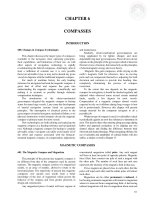
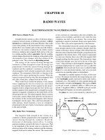
202. Defining the Ellipsoid
An ellipsoid of revolution is uniquely defined by
specifying two parameters. Geodesists, by convention, use
the semimajor axis and flattening. The size is represented
by the radius at the equator, the semimajor axis. The shape
of the ellipsoid is given by the flattening, which indicates
how closely an ellipsoid approaches a spherical shape. The
flattening is the ratio of the difference between the
semimajor and semiminor axes of the ellipsoid and the
semimajor axis. See Figure 202. If a and b represent the
semimajor and semiminor axes, respectively, of the
ellipsoid, and f is the flattening,
Figure 203. An ellipsoid which fits well in North America
may not fit well in Europe, whose ellipsoid must have a
different size, shape, and origin. Other ellipsoids are
necessary for other areas
204. Coordinates
Figure 202. An ellipsoid of revolution, with semimajor
axis (a), and semiminor axis (b).
The astronomic latitude is the angle between a plumb
line and the plane of the celestial equator. It is the latitude
which results directly from observations of celestial bodies,
uncorrected for deflection of the vertical component in the
meridian (north-south) direction. Astronomic latitude
applies only to positions on the Earth. It is reckoned from
the astronomic equator (0°), north and south through 90°.
The astronomic longitude is the angle between the
plane of the celestial meridian at a station and the plane of
the celestial meridian at Greenwich. It is the longitude
which results directly from observations of celestial bodies,
uncorrected for deflection of the vertical component in the
prime vertical (east-west) direction. These are the
GEODESY AND DATUMS IN NAVIGATION
coordinates observed by the celestial navigator using a
sextant and a very accurate clock based on the Earth’s
rotation.
Celestial observations by geodesists are made with
optical instruments (theodolite, zenith camera, prismatic
astrolabe) which all contain leveling devices. When
properly adjusted, the vertical axis of the instrument
coincides with the direction of gravity, which may not
coincides with the plane of the meridian. Thus, geodetically
derived astronomic positions are referenced to the geoid.
The difference, from a navigational standpoint, is too small
to be of concern.
The geodetic latitude is the angle which the normal to
the ellipsoid at a station makes with the plane of the
geodetic equator. In recording a geodetic position, it is
essential that the geodetic datum on which it is based also
be stated. A geodetic latitude differs from the
corresponding astronomic latitude by the amount of the
meridian component of the local deflection of the vertical.
The geodetic longitude is the angle between the plane
of the geodetic meridian at a station and the plane of the
geodetic meridian at Greenwich. A geodetic longitude
differs from the corresponding astronomic longitude by the
prime vertical component of the local deflection of the
vertical divided by the cosine of the latitude. The geodetic
coordinates are used for mapping.
17
The geocentric latitude is the angle at the center of the
ellipsoid (used to represent the Earth) between the plane of
the equator, and a straight line (or radius vector) to a point
on the surface of the ellipsoid. This differs from geodetic
latitude because the Earth is approximated more closely by
a spheroid than a sphere and the meridians are ellipses, not
perfect circles.
Both geocentric and geodetic latitudes refer to the
reference ellipsoid and not the Earth. Since the parallels of
latitude are considered to be circles, geodetic longitude is
geocentric, and a separate expression is not used.
Because of the oblate shape of the ellipsoid, the length
of a degree of geodetic latitude is not everywhere the same,
increasing from about 59.7 nautical miles at the equator to
about 60.3 nautical miles at the poles.
A horizontal geodetic datum usually consists of the
astronomic and geodetic latitude, and astronomic and
geodetic longitude of an initial point (origin); an azimuth of
a line (direction); the parameters (radius and flattening) of
the ellipsoid selected for the computations; and the geoidal
separation at the origin. A change in any of these quantities
affects every point on the datum.
For this reason, while positions within a given datum are
directly and accurately relatable, those from different datums
must be transformed to a common datum for consistency.
TYPES OF GEODETIC SURVEY
205. Triangulation
The most common type of geodetic survey is known as
triangulation. Triangulation consists of the measurement
of the angles of a series of triangles. The principle of
triangulation is based on plane trigonometry. If the distance
along one side of the triangle and the angles at each end are
accurately measured, the other two sides and the remaining
angle can be computed. In practice, all of the angles of
every triangle are measured to provide precise
measurements. Also, the latitude and longitude of one end
of the measured side along with the length and direction
(azimuth) of the side provide sufficient data to compute the
latitude and longitude of the other end of the side.
The measured side of the base triangle is called a
baseline. Measurements are made as carefully and
accurately as possible with specially calibrated tapes or
wires of Invar, an alloy with a very low coefficient of
expansion. The tape or wires are checked periodically
against standard measures of length.
To establish an arc of triangulation between two
widely separated locations, the baseline may be measured
and longitude and latitude determined for the initial points
at each location. The lines are then connected by a series of
adjoining triangles forming quadrilaterals extending from
each end. All angles of the triangles are measured
repeatedly to reduce errors. With the longitude, latitude,
and azimuth of the initial points, similar data is computed
for each vertex of the triangles, thereby establishing
triangulation stations, or geodetic control stations. The
coordinates of each of the stations are defined as geodetic
coordinates.
Triangulation is extended over large areas by
connecting and extending series of arcs to form a network
or triangulation system. The network is adjusted so as to
reduce observational errors to a minimum. A denser distribution of geodetic control is achieved by subdividing or
filling in with other surveys.
There are four general classes or orders of triangulation. First-order (primary) triangulation is the most
precise and exact type. The most accurate instruments and
rigorous computation methods are used. It is costly and
time-consuming, and is usually used to provide the basic
framework of control data for an area, and the determination of the figure of the Earth. The most accurate firstorder surveys furnish control points which can be
interrelated with an accuracy ranging from 1 part in 25,000
over short distances to approximately 1 part in 100,000 for
long distances.
Second-order triangulation furnishes points closer
together than in the primary network. While second-order
surveys may cover quite extensive areas, they are usually
18
GEODESY AND DATUMS IN NAVIGATION
tied to a primary system where possible. The procedures are
less exacting and the proportional error is 1 part in 10,000.
Third-order triangulation is run between points in a
secondary survey. It is used to densify local control nets and
position the topographic and hydrographic detail of the
area. Error can amount to 1 part in 5,000.
The sole accuracy requirement for fourth-order triangulation is that the positions be located without any appreciable
error on maps compiled on the basis of the control. Fourthorder control is done primarily as mapping control.
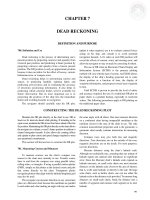
206. Trilateration, Traverse, And Vertical Surveying
Trilateration involves measuring the sides of a chain of
triangles or other polygons. From them, the distance and
direction from A to B can be computed. Figure 206 shows this
process.
Traverse involves measuring distances and the angles
between them without triangles for the purpose of
computing the distance and direction from A to B. See
Figure 206.
Vertical surveying is the process of determining
elevations above mean sea-level. In geodetic surveys executed
primarily for mapping, geodetic positions are referred to an
ellipsoid, and the elevations of the positions are referred to the
geoid. However, for satellite geodesy the geoidal heights must
be considered to establish the correct height above the geoid.
Precise geodetic leveling is used to establish a basic
network of vertical control points. From these, the height of
other positions in the survey can be determined by supple-
mentary methods. The mean sea-level surface used as a
reference (vertical datum) is determined by averaging the
hourly water heights for a specified period of time at
specified tide gauges.
There are three leveling techniques: differential,
trigonometric, and barometric. Differential leveling is the
most accurate of the three methods. With the instrument
locked in position, readings are made on two calibrated
staffs held in an upright position ahead of and behind the
instrument. The difference between readings is the
difference in elevation between the points.
Trigonometric leveling involves measuring a vertical
angle from a known distance with a theodolite and
computing the elevation of the point. With this method,
vertical measurement can be made at the same time
horizontal angles are measured for triangulation. It is,
therefore, a somewhat more economical method but less
accurate than differential leveling. It is often the only
mechanical method of establishing accurate elevation control
in mountainous areas.
In barometric leveling, differences in height are
determined by measuring the differences in atmospheric
pressure at various elevations. Air pressure is measured by
mercurial or aneroid barometer, or a boiling point
thermometer. Although the accuracy of this method is not
as great as either of the other two, it obtains relative heights
very rapidly at points which are fairly far apart. It is used in
reconnaissance and exploratory surveys where more
accurate measurements will be made later or where a high
degree of accuracy is not required.
Figure 206. Triangulation, trilateration, and traverse.
GEODESY AND DATUMS IN NAVIGATION
19
DATUM CONNECTIONS
207. Definitions
A datum is defined as any numerical or geometrical
quantity or set of such quantities which serves as a
reference point from which to measure other quantities.
In geodesy, cartography, and navigation, two general
types of datums must be considered: horizontal datum and
vertical datum. The horizontal datum forms the basis for
computations of horizontal position. The vertical datum
provides the reference to measure heights or depths, and may
be one of two types: Vertical geodetic datum is the reference
used by surveyors to measure heights of topographic features,
and by cartographers to portray them. This should not be
confused with the various types of tidal datums, which are by
definition vertical datums (and having no horizontal
component), used to define the heights and depths of
hydrographic features, such as water depths or bridge
clearances. The vertical geodetic datum is derived from its
mathematical expression, while the tidal datum is derived
from actual tidal data. For a complete discussion of tidal
datums, see Chapter 9.
This chapter will discuss only geodetic datums. For
navigational purposes, vertical geodetic datums are quite
unimportant, while horizontal geodetic datums and tidal
datums are vital.
A horizontal datum may be defined at an origin point on
the ellipsoid (local datum) such that the center of the ellipsoid
coincides with the Earth’s center of mass (geocentric datum).
The coordinates for points in specific geodetic surveys and
triangulation networks are computed from certain initial
quantities, or datums.
208. Preferred Datums
In areas of overlapping geodetic triangulation
networks, each computed on a different datum, the
coordinates of the points given with respect to one datum
will differ from those given with respect to the other. The
differences can be used to derive transformation formulas.
Datums are connected by developing transformation
formulas at common points, either between overlapping
control networks or by satellite connections.
Many countries have developed national datums which
differ from those of their neighbors. Accordingly, national
maps and charts often do not agree along national borders.
The North American Datum, 1927 (NAD 27) has
been used in the United States for about 60 years, but it is
being replaced by datums based on the World Geodetic
System. NAD 27 coordinates are based on the latitude and
longitude of a triangulation station (the reference point) at
Mead’s Ranch in Kansas, the azimuth to a nearby triangulation station called Waldo, and the mathematical
parameters of the Clarke Ellipsoid of 1866. Other datums
throughout the world use different assumptions as to origin
points and ellipsoids.
The origin of the European Datum is at Potsdam,
Germany. Numerous national systems have been joined
into a large datum based upon the International Ellipsoid of
1924 which was oriented by a modified astrogeodetic
method. European, African, and Asian triangulation chains
were connected, and African measurements from Cairo to
Cape Town were completed. Thus, all of Europe, Africa,
and Asia are molded into one great system. Through
common survey stations, it was also possible to convert
data from the Russian Pulkova, 1932 system to the
European Datum, and as a result, the European Datum
includes triangulation as far east as the 84th meridian.
Additional ties across the Middle East have permitted
connection of the Indian and European Datums.
The Ordnance Survey of Great Britain 1936 Datum
has no point of origin. The data was derived as a best fit
between retriangulation and original values of 11 points of
the earlier Principal Triangulation of Great Britain (17831853).
Tokyo Datum has its origin in Tokyo. It is defined in
terms of the Bessel Ellipsoid and oriented by a single
astronomic station. Triangulation ties through Korea connect
the Japanese datum with the Manchurian datum. Unfortunately, Tokyo is situated on a steep slope on the geoid, and the
single-station orientation has resulted in large systematic
geoidal separations as the system is extended from its initial
point.
The Indian Datum is the preferred datum for India and
several adjacent countries in Southeast Asia. It is computed
on the Everest Ellipsoid with its origin at Kalianpur, in
central India. It is largely the result of the untiring work of
Sir George Everest (1790-1866), Surveyor General in India
from 1830 to 1843. He is best known by the mountain
named after him, but by far his most important legacy was
the survey of the Indian subcontinent.
MODERN GEODETIC SYSTEMS
209. Development of the World Geodetic System
By the late 1950’s the increasing range and sophistication of weapons systems had rendered local or national
datums inadequate for military purposes; these new
weapons required datums at least continental, if not global,
in scope. In response to these requirements, the U.S.
Department of Defense generated a geocentric (earthcentered) reference system to which different geodetic
networks could be referred, and established compatibility
20
GEODESY AND DATUMS IN NAVIGATION
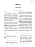
Figure 208. Major geodetic datum blocks.
between the coordinate systems. Efforts of the Army, Navy,
and Air Force were combined, leading to the development
of the DoD World Geodetic System of 1960 (WGS 60).
In January 1966, a World Geodetic System Committee
was charged with the responsibility for developing an
improved WGS needed to satisfy mapping, charting, and
geodetic requirements. Additional surface gravity
observations, results from the extension of triangulation and
trilateration networks, and large amounts of Doppler and
optical satellite data had become available since the
development of WGS 60. Using the additional data and
improved techniques, the Committee produced WGS 66
which served DoD needs following its implementation in
1967.
The same World Geodetic System Committee began
work in 1970 to develop a replacement for WGS 66. Since the
development of WGS 66, large quantities of additional data
had become available from both Doppler and optical satellites,
surface gravity surveys, triangulation and trilateration surveys,
high precision traverses, and astronomic surveys.
In addition, improved capabilities had been developed
in both computers and computer software. Continued
research in computational procedures and error analyses
had produced better methods and an improved facility for
handling and combining data. After an extensive effort
extending over a period of approximately three years, the
Committee completed the development of the Department
of Defense World Geodetic System 1972 (WGS 72).
Further refinement of WGS 72 resulted in the new World
Geodetic System of 1984 (WGS 84), now referred to as
simply WGS. For surface navigation, WGS 60, 66, 72 and the
new WGS 84 are essentially the same, so that positions
computed on any WGS coordinates can be plotted directly on
the others without correction.
The WGS system is not based on a single point, but
many points, fixed with extreme precision by satellite fixes
and statistical methods. The result is an ellipsoid which fits
the real surface of the Earth, or geoid, far more accurately
than any other. The WGS system is applicable worldwide.
All regional datums can be referenced to WGS once a
survey tie has been made.
GEODESY AND DATUMS IN NAVIGATION
210. The New North American Datum Of 1983
The Coast And Geodetic Survey of the National Ocean
Service (NOS), NOAA, is responsible for charting United
States waters. From 1927 to 1987, U.S. charts were based
on NAD 27, using the Clarke 1866 ellipsoid. In 1989, the
U.S. officially switched to NAD 83 (navigationally
equivalent to WGS) for all mapping and charting purposes,
and all new NOS chart production is based on this new
standard.
The grid of interconnected surveys which criss-crosses
the United States consists of some 250,000 control points,
each consisting of the latitude and longitude of the point,
plus additional data such as elevation. Converting the NAD
27 coordinates to NAD 83 involved recomputing the
position of each point based on the new NAD 83 datum. In
addition to the 250,000 U.S. control points, several
thousand more were added to tie in surveys from Canada,
Mexico, and Central America.
21
Conversion of new edition charts to the new datums,
either WGS 84 or NAD 83, involves converting reference
points on each chart from the old datum to the new, and
adjusting the latitude and longitude grid (known as the
graticule) so that it reflects the newly plotted positions. This
adjustment of the graticule is the only difference between
charts which differ only in datum. All charted features
remain in exactly the same relative positions.
The Global Positioning System (GPS) has transformed
the science of surveying, enabling the establishment of
precise ties to WGS in areas previously found to be too
remote to survey to modern standards. As a result, new
charts are increasingly precise as to position of features.
The more recent a chart’s date of publishing, the more
likely it is that it will be accurate as to positions. Navigators
should always refer to the title block of a chart to determine
the date of the chart, the date of the surveys and sources
used to compile it, and the datum on which it is based.
DATUMS AND NAVIGATION
211. Datum Shift
One of the most serious impacts of different datums on
navigation occurs when a navigation system provides a fix
based on a datum different from that used for the nautical
chart. The resulting plotted position may be different from
the actual location on that chart. This difference is known
as a datum shift.
Modern electronic navigation systems have software
installed that can output positions in a variety of datums,
eliminating the necessity for applying corrections. All electronic charts produced by NIMA are compiled on WGS and
are not subject to datum shift problems as long as the GPS
receiver is outputting WGS position data to the display system. The same is true for NOAA charts of the U.S., which
are compiled on NAD 83 datum, very closely related to
WGS. GPS receivers, including the WRN-6, default to
WGS, so that no action is necessary to use any U.S.-produced electronic charts.
To automate datum conversions, a number of datum
transformation software programs have been written that
will convert from any known datum to any other, in any location. MADTRAN and GEOTRANS-2 are two such
programs. The amount of datum shift between two different
datums is not linear. That is, the amount of shift is a function of the position of the observer, which must be specified
for the shift to be computed. Varying differences of latitude
and longitude between two different datums will be noted
as one’s location changes.
There are still a few NIMA-produced paper charts, and
a number of charts from other countries, based on datums
other than WGS. If the datum of these charts is noted in the
title block of the chart, the WRN-6 and most other GPS re-
ceivers can be set to output position data in that datum,
eliminating the datum shift problem. If the datum is not listed, extreme caution is necessary. An offset can sometimes
be established if the ship’s actual position can be determined with sufficient accuracy, and this offset applied to
GPS positions in the local area. But remember that since a
datum shift is not linear, this offset is only applicable
locally.
Another effect on navigation occurs when shifting
between charts that have been compiled using different
datums. If a position is replotted on a chart of another datum
using latitude and longitude, the newly plotted position will
not match with respect to other charted features. The datum
shift may be avoided by transferring positions using
bearings and ranges to common points. If datum shift
conversion notes for the applicable datums are given on the
charts, positions defined by latitude and longitude may be
replotted after applying the noted correction.
The positions given for chart corrections in the Notice to
Mariners reflect the proper datum for each specific chart and
edition number. Due to conversion of charts based on old
datums to more modern ones, and the use of many different
datums throughout the world, chart corrections intended for
one edition of a chart may not be safely plotted on any other.
As noted, datum shifts are not constant throughout a
given region, but vary according to how the differing
datums fit together. For example, the NAD 27 to NAD 83
conversion resulted in changes in latitude of 40 meters in
Miami, 11 meters in New York, and 20 meters in Seattle.
Longitude changes for this conversion amounted to 22
meters in Miami, 35 meters in New York, and 93 meters in
Seattle.
Most charts produced by NIMA and NOS show a
22
GEODESY AND DATUMS IN NAVIGATION
“datum note.” This note is usually found in the title block
or in the upper left margin of the chart. According to the
year of the chart edition, the scale, and policy at the time of
production, the note may say “World Geodetic System
1972 (WGS-72)”, “World Geodetic System 1984 (WGS84)”, or “World Geodetic System (WGS).” A datum note
for a chart for which satellite positions can be plotted
without correction will read: “Positions obtained from
satellite navigation systems referred to (Reference Datum)
can be plotted directly on this chart.”
NIMA reproductions of foreign charts will usually be
in the datum or reference system of the producing country.
In these cases a conversion factor is given in the following
format: “Positions obtained from satellite navigation
systems referred to the (Reference Datum) must be moved
X.XX minutes (Northward/Southward) and X.XX minutes
(Eastward/ Westward) to agree with this chart.”
Some charts cannot be tied in to WGS because of lack
of recent surveys. Currently issued charts of some areas are
based on surveys or use data obtained in the age of sailing
ships. The lack of surveyed control points means that they
cannot be properly referenced to modern geodetic systems.
In this case there may be a note that says: “Adjustments to
WGS cannot be determined for this chart.”
A few charts may have no datum note at all, but may
carry a note which says: “From various sources to (year).”
In these cases there is no way for the navigator to determine
the mathematical difference between the local datum and
WGS positions. However, if a radar or visual fix can be
accurately determined, and an offset established as noted
above. This offset can then be programmed into the GPS
receiver.
To minimize problems caused by differing datums:
• Plot chart corrections only on the specific charts and editions for which they are intended. Each chart correction
is specific to only one edition of a chart. When the same
correction is made on two charts based on different datums, the positions for the same feature may differ
slightly. This difference is equal to the datum shift between the two datums for that area.
• Try to determine the source and datum of positions of
temporary features, such as drill rigs. In general they are
given in the datum used in the area in question. Since
these are precisely positioned using satellites, WGS is
the normal datum. A datum correction, if needed, might
be found on a chart of the area.
• Remember that if the datum of a plotted feature is not
known, position inaccuracies may result. It is wise to
allow a margin of error if there is any doubt about the
datum.
• Know how the datum of the positioning system you
are using (Loran, GPS, etc.) relates to your chart.
GPS and other modern positioning systems use
WGS datum. If your chart is on any other datum, you
must program the system to use the chart’s datum, or
apply a datum correction when plotting GPS
positions on the chart.