the american practical navigator chapt 05
Bạn đang xem bản rút gọn của tài liệu. Xem và tải ngay bản đầy đủ của tài liệu tại đây (693.27 KB, 18 trang )
CHAPTER 5
SHORT RANGE AIDS TO NAVIGATION
DEFINING SHORT RANGE AIDS TO NAVIGATION
500. Terms and Definitions
Short range aids to navigation are those intended to be
used visually or by radar while in inland, harbor and
approach, and coastal navigation. The term encompasses
lighted and unlighted beacons, ranges, leading lights,
buoys, and their associated sound signals. Each short range
aid to navigation, commonly referred to as a NAVAID, fits
within a system designed to warn the mariner of dangers
and direct him toward safe water. An aid’s function
determines its color, shape, light characteristic, and sound.
This chapter explains the U.S. Aids to Navigation System
as well as the IALA Maritime Buoyage System.
The placement and maintenance of marine aids to
navigation in U.S. waters is the responsibility of the United
States Coast Guard. The Coast Guard maintains
lighthouses, radiobeacons, racons, sound signals, buoys,
and daybeacons on the navigable waters of the United
States, its territories, and possessions. Additionally, the
Coast Guard exercises control over privately owned
navigation aid systems.
A beacon is a stationary, visual navigation aid. Large
lighthouses and small single-pile structures are both
beacons. Lighted beacons are called lights; unlighted
beacons are daybeacons. All beacons exhibit a daymark
of some sort. In the case of a lighthouse, the color and type
of structure are the daymarks. On small structures, these
daymarks, consisting of colored geometric shapes called
dayboards, often have lateral significance. The markings
on lighthouses and towers convey no lateral significance.
FIXED LIGHTS
501. Major and Minor Lights
Lights vary from tall, high intensity coastal lights to
battery-powered lanterns on single wooden piles.
Immovable, highly visible, and accurately charted, fixed
lights provide navigators with an excellent source for
bearings. The structures are often distinctively colored to
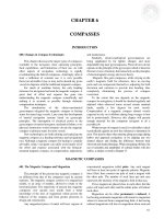
aid in identification. See Figure 501a.
A major light is a high-intensity light exhibited from
a fixed structure or a marine site. Major lights include
primary seacoast lights and secondary lights. Primary
seacoast lights are major lights established for making
landfall from sea and coastwise passages from headland to
headland. Secondary lights are major lights established at
harbor entrances and other locations where high intensity
and reliability are required.
A minor light usually displays a light of low to
moderate intensity. Minor lights are established in harbors,
along channels, rivers, and in isolated locations. They
usually have numbering, coloring, and light and sound
characteristics that are part of the lateral system of buoyage.
Lighthouses are placed where they will be of most use:
on prominent headlands, at harbor and port entrances, on
isolated dangers, or at other points where mariners can best
use them to fix their position. The lighthouse’s principal
purpose is to support a light at a considerable height above
the water, thereby increasing its geographic range. Support
equipment is often housed near the tower.
With few exceptions, all major lights operate automatically. There are also many automatic lights on smaller
structures maintained by the Coast Guard or other
attendants. Unmanned major lights may have emergency
generators and automatic monitoring equipment to increase
the light’s reliability.
Light structures’ appearances vary. Lights in low-lying
areas usually are supported by tall towers; conversely, light
structures on high cliffs may be relatively short. However
its support tower is constructed, almost all lights are
similarly generated, focused, colored, and characterized.
Some major lights use modern rotating or flashing
lights, but many older lights use Fresnel lenses. These
lenses consist of intricately patterned pieces of glass in a
heavy brass framework. Modern Fresnel-type lenses are
cast from high-grade plastic; they are much smaller and
lighter than their glass counterparts.
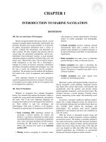
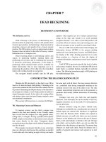
A buoyant beacon provides nearly the positional accuracy of a light in a place where a buoy would normally be
used. See Figure 501b. The buoyant beacon consists of a
heavy sinker to which a pipe structure is tightly moored. A
buoyancy chamber near the surface supports the pipe. The
light, radar reflector, and other devices are located atop the
pipe above the surface of the water. The pipe with its buoyancy chamber tends to remain upright even in severe
weather and heavy currents, providing a smaller watch cir63
64
SHORT RANGE AIDS TO NAVIGATION
Figure 501a. Typical offshore light station.
Figure 501b. Typical design for a buoyant beacon.
cle than a buoy. The buoyant beacon is most useful along
narrow ship channels in relatively sheltered water.
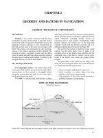
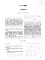
502. Range Lights
Range lights are light pairs that indicate a specific line
of position when they are in line. The higher rear light is
placed behind the front light. When the mariner sees the
lights vertically in line, he is on the range line. If the front
light appears left of the rear light, the observer is to the right
of the range line; if the front appears to the right of the rear,
the observer is left of the range line. Range lights are
sometimes equipped with high intensity lights for daylight
use. These are effective for long channels in hazy
conditions when dayboards might not be seen. The range
light structures are usually also equipped with dayboards
for ordinary daytime use. Some smaller ranges, primarily in
the Intercoastal Waterway, rivers, and other inland waters,
have just the dayboards with no lights. See Figure 502.
To enhance the visibility of range lights, the Coast
Guard has developed 15-foot long lighted tubes called light
pipes. They are mounted vertically, and the mariner sees
them as vertical bars of light distinct from background
lighting. Installation of light pipes is proceeding on several
range markers throughout the country. The Coast Guard is
also experimenting with long range sodium lights for areas
requiring visibility greater than the light pipes can provide.
The output from a low pressure sodium light is almost
entirely at one wavelength. This allows the use of an
inexpensive band-pass filter to make the light visible even
during the daytime. This arrangement eliminates the need
for high intensity lights with their large power requirements.
Range lights are usually white, red, or green. They
display various characteristics differentiating them from
surrounding lights.
A directional light is a single light that projects a high
intensity, special characteristic beam in a given direction. It
is used in cases where a two-light range may not be practicable. A directional sector light is a directional light that
emits two or more colored beams. The beams have a pre-
SHORT RANGE AIDS TO NAVIGATION
65
Figure 502. Range lights.
cisely oriented boundary between them. A normal
application of a sector light would show three colored sections: red, white, and green. The white sector would
indicate that the vessel is on the channel centerline; the
green sector would indicate that the vessel is off the channel
centerline in the direction of deep water; and the red sector
would indicate that the vessel is off the centerline in the
direction of shoal water.
503. Aeronautical Lights
Aeronautical lights may be the first lights observed at
night when approaching the coast. Those situated near the
coast and visible from sea are listed in the List of Lights.
These lights are not listed in the Coast Guard Light List.
They usually flash alternating white and green.
Aeronautical lights are sequenced geographically in the
List of Lights along with marine navigation lights. However,
since they are not maintained for marine navigation, they are
subject to changes of which maritime authorities may not be
informed. These changes will be published in Notice to
Airmen but perhaps not in Notice to Mariners.
504. Bridge Lights
Navigational lights on bridges in the U.S. are prescribed
by Coast Guard regulations. Red, green, and white lights
mark bridges across navigable waters. Red lights mark piers
and other parts of the bridge. Red lights are also used on
drawbridges to show when they are in the closed position.
Green lights mark open drawbridges and mark the centerline
of navigable channels through fixed bridges. The position will
vary according to the type of structure.
Infrequently-used bridges may be unlighted. In foreign
waters, the type and method of lighting may be different from
those normally found in the United States. Drawbridges which
must be opened to allow passage operate upon sound and light
signals given by the vessel and acknowledged by the bridge.
These required signals are detailed in the Code of Federal
Regulations and the applicable Coast Pilot. Certain bridges
may also be equipped with sound signals and radar reflectors.
505. Shore Lights
Shore lights usually have a shore-based power supply.
Lights on pilings, such as those found in the Intracoastal
Waterway, are battery powered. Solar panels may be installed
to enhance the light’s power supply. The lights consist of a
power source, a flasher to determine the characteristic, a lamp
changer to replace burned-out lamps, and a focusing lens.
Various types of rotating lights are in use. They do not
have flashers but remain continuously lit while a lens or
reflector rotates around the horizon.
The aids to navigation system is carefully engineered
66
SHORT RANGE AIDS TO NAVIGATION
to provide the maximum amount of direction to the mariner
for the least expense. Specially designed filaments and
special grades of materials are used in the light to withstand
the harsh marine environment.
The flasher electronically determines the characteristic by selectively interrupting the light’s power supply
according to the chosen cycle.
The lamp changer consists of several sockets
arranged around a central hub. When the circuit is broken
by a burned-out filament, a new lamp is rotated into
position. Almost all lights have daylight switches which
turn the light off at sunrise and on at dusk.
The lens for small lights may be one of several types.
The common ones in use are omni-directional lenses of
155mm, 250mm, and 300mm diameter. In addition, lights
using parabolic mirrors or focused-beam lenses are used in
leading lights and ranges. The lamp filaments must be
carefully aligned with the plane of the lens or mirror to
provide the maximum output of light. The lens’ size is
chosen according to the type of platform, power source, and
lamp characteristics. Additionally, environmental characteristics of the location are considered. Various types of
light-condensing panels, reflex reflectors, or colored sector
panels may be installed inside the lens to provide the proper
characteristic. A specially reinforced 200mm lantern is
used in locations where ice and breaking water are a hazard.
LIGHT CHARACTERISTICS
506. Characteristics
A light has distinctive characteristics which
distinguish it from other lights or convey specific
information by showing a distinctive sequence of light and
dark intervals. Additionally, a light may display a
distinctive color or color sequence. In the Light Lists, the
dark intervals are referred to as eclipses.
An occulting light is a light totally eclipsed at regular
intervals, the duration of light always being greater than the
duration of darkness. A flashing light flashes on and off at
regular intervals, the duration of light always being less
than the duration of darkness. An isophase light flashes at
regular intervals, the duration of light being equal to the
duration of darkness.
Light phase characteristics (See Table 506) are the
distinctive sequences of light and dark intervals or
sequences in the variations of the luminous intensity of a
light. The light phase characteristics of lights which change
color do not differ from those of lights which do not change
color. A light showing different colors alternately is
described as an alternating light. The alternating characteristic may be used with other light phase characteristics.
TYPE
ABBREVIATION
Fixed
F.
Occulting
Oc.
The total duration of light in a period is
longer than the total duration of darkness
and the intervals of darkness (eclipses)
are usually of equal duration. Eclipse
regularly repeated.
Group occulting
Oc.(2)
An occulting light for which a group of
eclipses, specified in number, is regularly
repeated.
Composite group
occulting
Oc.(2+1)
A light similar to a group occulting light
except that successive groups in a period
have different numbers of eclipses.
Isophase
Iso
A light for which all durations of light and
darkness are clearly equal.
GENERAL DESCRIPTION
A continuous and steady light.
Table 506. Light phase characteristics.
ILLUSTRATION*
SHORT RANGE AIDS TO NAVIGATION
TYPE
ABBREVIATION
GENERAL DESCRIPTION
Flashing
Fl.
A light for which the total duration of
light in a period is shorter than the total
duration of darkness and the appearances
of light (flashes) are usually of equal
duration (at a rate of less than 50 flashes
per minute).
Long flashing
L.Fl.
A single flashing light for which an
appearance of light of not less than 2 sec.
duration (long flash) is regularly repeated.
Group flashing
Fl.(3)
A flashing light for which a group of
flashes, specified in number, is regularly
repeated.
Composite group
flashing
Fl.(2+1)
A light similar to a group flashing light
except that successive groups in a period
have different numbers of flashes.
Quick flashing
Q.
A light for which a flash is regularly
repeated at a rate of not less than 50
flashes per minute but less than 80 flashes
per minute.
Group quick
flashing
Q.(3)
A light for which a specified group of
flashes is regularly repeated; flashes are
repeated at a rate of not less than 50
flashes per minute but less than 80 flashes
per minute.
Q.(9)
Q.(6)+L.Fl.
Interrupted quick
flashing
I.Q.
A light for which the sequence of quick
flashes is interrupted by regularly
repeated eclipses of constant and long
duration.
Very quick
flashing
V.Q.
A light for which a flash is regularly
repeated at a rate of not less than 80
flashes per minute but less than 160
flashes per minute.
Table 506. Light phase characteristics.
67
ILLUSTRATION*
68
SHORT RANGE AIDS TO NAVIGATION
TYPE
ABBREVIATION
GENERAL DESCRIPTION
Group very quick
flashing
V.Q.(3)
A light for which a specified group of very
quick flashes is regularly repeated.
ILLUSTRATION*
V.Q.(9)
V.Q.(6)+L.Fl.
Interrupted very
quick flashing
I.V.Q.
A light for which the sequence of very
quick flashes is interrupted by regularly
repeated eclipses of constant and long
duration.
Ultra quick
flashing
U.Q.
A light for which a flash is regularly
repeated at a rate of not less than 160
flashes per minute.
Interrupted ultra
quick flashing
I.U.Q.
A light for which the sequence of ultra
quick flashes is interrupted by regularly
repeated eclipses of constant and long
duration.
Morse code
Mo.(U)
A light for which appearances of light of
two clearly different durations are
grouped to represent a character or
characters in Morse Code.
Fixed and flashing
F.Fl.
A light for which a fixed light is combined
with a flashing light of greater luminous
intensity
.
Alternate light
Al.
A light showing
alternately
different
colors
NOTE: Alternating lights may be used in combined
form with most of the previous types of lights
Table 506. Light phase characteristics.
* Periods shown are examples
only.
SHORT RANGE AIDS TO NAVIGATION
Light-sensitive switches extinguish most lighted
navigation aids during daylight hours. However, owing to
the various sensitivities of the light switches, all lights do
not turn on or off at the same time. Mariners should account
for this when identifying aids to navigation during twilight
periods when some lighted aids are on while others are not.
507. Light Sectors
Sectors of colored glass or plastic are sometimes
placed in the lanterns of certain lights to indicate dangerous
waters. Lights so equipped show different colors when
observed from different bearings. A sector changes the
color of a light, but not its characteristic, when viewed from
certain directions. For example, a four second flashing
white light having a red sector will appear as a four second
flashing red light when viewed from within the red sector.
Sectors may be only a few degrees in width or extend
in a wide arc from deep water toward shore. Bearings
referring to sectors are expressed in degrees true as
observed from a vessel. In most cases, areas covered by red
sectors should be avoided. The nature of the danger can be
determined from the chart. In some cases a narrow sector
may mark the best water across a shoal, or a turning point
in a channel.
The transition from one color to another is not abrupt.
The colors change through an arc of uncertainty of 2° or
greater, depending on the optical design of the light.
Therefore determining bearings by observing the color
change is less accurate than obtaining a bearing with an
azimuth circle.
508. Factors Affecting Range and Characteristics
The condition of the atmosphere has a considerable effect
upon a light’s range. Lights are sometimes obscured by fog,
haze, dust, smoke, or precipitation. On the other hand,
refraction may cause a light to be seen farther than under
ordinary circumstances. A light of low intensity will be easily
obscured by unfavorable conditions of the atmosphere. For
this reason, the intensity of a light should always be considered
when looking for it in thick weather. Haze and distance may
reduce the apparent duration of a light’s flash. In some
conditions of the atmosphere, white lights may have a reddish
hue. In clear weather green lights may have a more whitish
hue.
Lights placed at higher elevations are more frequently
obscured by clouds, mist, and fog than those near sea level.
In regions where ice conditions prevail, an unattended
light’s lantern panes may become covered with ice or snow
This may reduce the light’s luminous range and change the
light’s observed color.
The distance from a light cannot be estimated by its
apparent brightness. There are too many factors which can
69
change the perceived intensity. Also, a powerful, distant
light may sometimes be confused with a smaller, closer one
with similar characteristics. Every light sighted should be
carefully evaluated to determine if it is the one expected.
The presence of bright shore lights may make it
difficult to distinguish navigational lights from background
lighting. Lights may also be obscured by various shore
obstructions, natural and man-made. The Coast Guard
requests mariners to report these cases to the nearest Coast
Guard station.
A light’s loom is sometimes seen through haze or the
reflection from low-lying clouds when the light is beyond
its geographic range. Only the most powerful lights can
generate a loom. The loom may be sufficiently defined to
obtain a bearing. If not, an accurate bearing on a light
beyond geographic range may sometimes be obtained by
ascending to a higher level where the light can be seen, and
noting a star directly over the light. The bearing of the star
can then be obtained from the navigating bridge and the
bearing to the light plotted indirectly.
At short distances, some of the brighter flashing lights
may show a faint continuous light, or faint flashes, between
regular flashes. This is due to reflections of a rotating lens
on panes of glass in the lighthouse.
If a light is not sighted within a reasonable time after
prediction, a dangerous situation may exist. Conversely, the
light may simply be obscured or extinguished. The ship’s
position should immediately be fixed by other means to
determine any possibility of danger.
The apparent characteristic of a complex light may
change with the distance of the observer. For example, a
light with a characteristic of fixed white and alternating
flashing white and red may initially show as a simple
flashing white light. As the vessel draws nearer, the red
flash will become visible and the characteristic will
apparently be alternating flashing white and red. Later, the
fainter fixed white light will be seen between the flashes
and the true characteristic of the light finally recognized as
fixed white, alternating flashing white and red (F W Al W
R). This is because for a given candlepower, white is the
most visible color, green less so, and red least of the three.
This fact also accounts for the different ranges given in the
Light Lists for some multi-color sector lights. The same
lamp has different ranges according to the color imparted
by the sector glass.
A light may be extinguished due to weather, battery
failure, vandalism, or other causes. In the case of
unattended lights, this condition might not be immediately
corrected. The mariner should report this condition to the
nearest Coast Guard station. During periods of armed
conflict, certain lights may be deliberately extinguished
without notice. Offshore light stations should always be left
well off the course whenever searoom permits.
70
SHORT RANGE AIDS TO NAVIGATION
BUOYS
509. Definitions and Types
Buoys are floating aids to navigation. They mark
channels, indicate shoals and obstructions, and warn the
mariner of dangers. Buoys are used where fixed aids would
be uneconomical or impractical due to the depth of water.
By their color, shape, topmark, number, and light characteristics, buoys indicate to the mariner how to avoid hazards
and stay in safe water. The federal buoyage system in the
U.S. is maintained by the Coast Guard.
There are many different sizes and types of buoys
designed to meet a wide range of environmental conditions
and user requirements. The size of a buoy is determined
primarily by its location. In general, the smallest buoy
which will stand up to local weather and current conditions
is chosen.
There are five types of buoys maintained by the Coast
Guard. They are:
1.
2.
3.
4.
5.
Lateral marks
Isolated danger marks
Safe water marks
Special marks
Information/regulatory marks
These conform in general to the specifications of the
International Association of Lighthouse Authorities
(IALA) buoyage system.
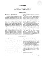
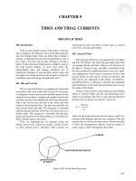
A lighted buoy is a floating hull with a tower on which
a light is mounted. Batteries for the light are in watertight
pockets in the buoy hull or in watertight boxes mounted on
the buoy hull. To keep the buoy in an upright position, a
counterweight is attached to the hull below the water’s
surface. A radar reflector is built into the buoy tower.
The largest of the typical U.S. Coast Guard buoys can
be moored in up to 190 feet of water, limited by the weight
of chain the hull can support. The focal plane of the light is
15 to 20 feet high. The designed nominal visual range is 3.8
miles, and the radar range 4 miles. Actual conditions will
cause these range figures to vary considerably.
The smallest buoys are designed for protected water.
Some are made of plastic and weigh only 40 pounds.
Specially designed buoys are used for fast current, ice, and
other environmental conditions.
A variety of special purpose buoys are owned by other
governmental organizations. Examples of these organizations include the St. Lawrence Seaway Development
Corporation, NOAA, and the Department of Defense.
These buoys are usually navigational marks or data
collection buoys with traditional round, boat-shaped, or
discus-shaped hulls.
A special class of buoy, the Ocean Data Acquisition
System (ODAS) buoy, is moored or floats free in offshore
Figure 509. Buoy showing counterweight.
waters. Positions are promulgated through radio warnings.
These buoys are generally not large enough to cause
damage to a large vessel in a collision, but should be given
a wide berth regardless, as any loss would almost certainly
result in the interruption of valuable scientific experiments.
They are generally bright orange or yellow in color, with
vertical stripes on moored buoys and horizontal bands on
free-floating ones, and have a strobe light for night
visibility.
Even in clear weather, the danger of collision with a
buoy exists. If struck head-on, a large buoy can inflict
severe damage to a large ship; it can sink a smaller one.
Reduced visibility or heavy background lighting can
contribute to the problem of visibility. The Coast Guard
sometimes receives reports of buoys missing from station
that were actually run down and sunk. Tugboats and
towboats towing or pushing barges are particularly
dangerous to buoys because of poor over-the-bow visibility
when pushing or yawing during towing. The professional
mariner must report any collision with a buoy to the nearest
Coast Guard unit. Failure to do so may cause the next vessel
to miss the channel or hit the obstruction marked by the
buoy; it can also lead to fines and legal liability.
Routine on-station buoy maintenance consists of
inspecting the mooring, cleaning the hull and
superstructure, replacing the batteries, flasher, and lamps,
checking wiring and venting systems, and verifying the
buoy’s exact position. Every few years, each buoy is
replaced by a similar aid and returned to a Coast Guard
maintenance facility for complete refurbishment.
The placement of a buoy depends on its purpose and its
position on the chart. Most buoys are placed on their charted
positions as accurately as conditions allow. However, if a
SHORT RANGE AIDS TO NAVIGATION
buoy’s purpose is to mark a shoal and the shoal is found to be
in a different position than the chart shows, the buoy will be
placed to properly mark the shoal, and not on its charted
position.
510. Lights on Buoys
Buoy light systems consist of a battery pack, a flasher
which determines the characteristic, a lamp changer which
automatically replaces burned-out bulbs, a lens to focus the
light, and a housing which supports the lens and protects
the electrical equipment.
The batteries consist of 12-volt lead/acid type
batteries electrically connected to provide sufficient power
to run the proper flash characteristic and lamp size. These
battery packs are contained in pockets in the buoy hull,
accessible through water-tight bolted hatches or externally
mounted boxes. Careful calculations based on light characteristics determine how much battery power to install.
The flasher determines the characteristic of the lamp.
It is installed in the housing supporting the lens.
The lamp changer consists of several sockets
arranged around a central hub. A new lamp rotates into
position if the active one burns out.
Under normal conditions, the lenses used on buoys are
155mm in diameter at the base. 200 mm lenses are used
where breaking waves or swells call for the larger lens.
They are colored according to the charted characteristic of
the buoy. As in shore lights, the lamp must be carefully
focused so that the filament is directly in line with the focal
plane of the lens. This ensures that the majority of the light
produced is focused in a 360° horizontal fan beam. A buoy
light has a relatively narrow vertical profile. Because the
buoy rocks in the sea, the focal plane may only be visible
for fractions of a second at great ranges. A realistic range
for sighting buoy lights is 4-6 miles in good visibility and
calm weather.
511. Sound Signals on Buoys
Lighted sound buoys have the same general configuration as lighted buoys but are equipped with either a bell,
gong, whistle, or horn. Bells and gongs are sounded by
tappers hanging from the tower that swing as the buoy rocks
in the sea. Bell buoys produce only one tone; gong buoys
produce several tones. The tone-producing device is
mounted between the legs of the pillar or tower.
Whistle buoys make a loud moaning sound caused by
the rising and falling motions of the buoy in the sea. A
sound buoy equipped with an electronic horn will produce
a pure tone at regular intervals regardless of the sea state.
Unlighted sound buoys have the same general appearance
as lighted buoys, but their underwater shape is designed to
make them lively in all sea states.
71
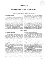
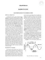
512. Buoy Moorings
Buoys require moorings to hold them in position.
Typically the mooring consists of chain and a large
concrete or cast iron sinker. See Figure 512. Because buoys
are subjected to waves, wind, and tides, the moorings must
be deployed with chain lengths much greater than the water
depth. The scope of chain will normally be about 3 times
the water depth. The length of the mooring chain defines a
watch circle within which the buoy can be expected to
swing. It is for this reason that the charted buoy symbol has
a “position approximate” circle to indicate its charted
position, whereas a light position is shown by a dot at the
exact location. Actual watch circles do not necessarily
coincide with the “position approximate” circles which
represent them.
Figure 512. A sinker used to anchor a buoy.
Over several years, the chain gradually wears out and
must be replaced. The worn chain is often cast into the
concrete of new sinkers.
513. Large Navigational Buoys
Large navigational buoys are moored in open water
at approaches to certain major seacoast ports and monitored
from shore stations by radio signals. These 40-foot
diameter buoys (Figure 513) show lights from heights of
about 36 feet above the water. Emergency lights automatically energize if the main light is extinguished. These
buoys may also have a radiobeacon and sound signals.
514. Wreck Buoys
A wreck buoy usually cannot be placed directly over
the wreck it is intended to mark because the buoy tender
may not want to pass over a shallow wreck or risk fouling
the buoy mooring. For this reason, a wreck buoy is usually
72
SHORT RANGE AIDS TO NAVIGATION
Figure 513. Large navigational buoy.
placed as closely as possible on the seaward or channelward
side of a wreck. In some situations, two buoys may be used
to mark the wreck, one lying off each end. The wreck may
lie directly between them or inshore of a line between them,
depending on the local situation. The Local Notice to
Mariners should be consulted concerning details of the
placement of wreck buoys on individual wrecks. Often it
will also give particulars of the wreck and what activities
may be in progress to clear it.
The charted position of a wreck buoy will usually be
offset from the actual geographic position so that the wreck
and buoy symbols do not coincide. Only on the largest scale
chart will the actual and charted positions of both wreck and
buoy be the same. Where they might overlap, it is the wreck
symbol which occupies the exact charted position and the
buoy symbol which is offset.
Wreck buoys are required to be placed by the owner of
the wreck, but they may be placed by the Coast Guard if the
owner is unable to comply with this requirement. In general,
privately placed aids are not as reliable as Coast Guard aids.
Sunken wrecks are sometimes moved away from their
buoys by storms, currents, freshets, or other causes. Just as
shoals may shift away from the buoys placed to mark them,
wrecks may shift away from wreck buoys.
515. Fallibility of Buoys
Buoys cannot be relied on to maintain their charted
positions consistently. They are subject to a variety of
hazards including severe weather, collision, mooring
casualties, and electrical failure. Mariners should report
discrepancies to the authority responsible for maintaining
the aid.
The buoy symbol shown on charts indicates the
approximate position of the sinker which secures the buoy
to the seabed. The approximate position is used because of
practical limitations in keeping buoys in precise
geographical locations. These limitations include
prevailing atmospheric and sea conditions, the slope and
type of material making up the seabed, the scope of the
SHORT RANGE AIDS TO NAVIGATION
mooring chain, and the fact that the positions of the buoys
and the sinkers are not under continuous surveillance. The
position of the buoy shifts around the area shown by the
chart symbol due to the forces of wind and current.
A buoy may not be in its charted position because of
changes in the feature it marks. For example, a buoy meant to
mark a shoal whose boundaries are shifting might frequently be
moved to mark the shoal accurately. A Local Notice to Mariners
will report the change, and a Notice to Mariners chart correction
73
may also be written. In some small channels which change
often, buoys are not charted even when considered permanent;
local knowledge is advised in such areas.
For these reasons, a mariner must not rely completely
upon the position or operation of buoys, but should
navigate using bearings of charted features, structures, and
aids to navigation on shore. Further, a vessel attempting to
pass too close aboard a buoy risks a collision with the buoy
or the obstruction it marks.
BUOYAGE SYSTEMS
516. Lateral and Cardinal Systems
There are two major types of buoyage systems: the
lateral system and the cardinal system. The lateral
system is best suited for well-defined channels. The
description of each buoy indicates the direction of danger
relative to the course which is normally followed. In
principle, the positions of marks in the lateral system are
determined by the general direction taken by the mariner
when approaching port from seaward. These positions
may also be determined with reference to the main stream
of flood current. The United States Aids to Navigation
System is a lateral system.
The cardinal system is best suited for coasts with
numerous isolated rocks, shoals, and islands, and for
dangers in the open sea. The characteristic of each buoy
indicates the approximate true bearing of the danger it
marks. Thus, an eastern quadrant buoy marks a danger
which lies to the west of the buoy. The following pages
diagram the cardinal and lateral buoyage systems as found
outside the United States.
517. The IALA Maritime Buoyage System
Although most of the major maritime nations have
used either the lateral or the cardinal system for many years,
details such as the buoy shapes and colors have varied from
country to country. With the increase in maritime
commerce between countries, the need for a uniform
system of buoyage became apparent.
In 1889, an International Marine Conference held in
Washington, D.C., recommended that in the lateral system,
starboard hand buoys be painted red and port hand buoys
black. Unfortunately, when lights for buoys were
introduced some years later, some European countries
placed red lights on the black port hand buoys to conform
with the red lights marking the port side of harbor
entrances, while in North America red lights were placed on
red starboard hand buoys. In 1936, a League of Nations
subcommittee recommended a coloring system opposite to
the 1889 proposal.
The International Association of Lighthouse
Authorities (IALA) is a non-governmental organization
which consists of representatives of the worldwide
community of aids to navigation services. It promotes
information exchange and recommends improvements
based on new technologies. In 1980, with the assistance of
IMO and the IHO, the lighthouse authorities from 50
countries and representatives of 9 international organizations concerned with aids to navigation met and adopted
the IALA Maritime Buoyage System. They established
two regions, Region A and Region B, for the entire world.
Region A roughly corresponds to the 1936 League of
Nations system, and Region B to the older 1889 system.
Lateral marks differ between Regions A and B. Lateral
marks in Region A use red and green colors by day and night
to indicate port and starboard sides of channels, respectively.
In Region B, these colors are reversed with red to starboard
and green to port. In both systems, the conventional direction
of buoyage is considered to be returning from sea, hence the
phrase “red right returning” in IALA region B.
518. Types of Marks
The IALA Maritime Buoyage System applies to all
fixed and floating marks, other than lighthouses, sector
lights, range lights, daymarks, lightships and large navigational buoys, which indicate:
1.
2.
3.
4.
The side and center-lines of navigable channels
Natural dangers, wrecks, and other obstructions
Regulated navigation areas
Other important features
Most lighted and unlighted beacons other than range
marks are included in the system. In general, beacon
topmarks will have the same shape and colors as those used
on buoys. The system provides five types of marks which
may be used in any combination:
1. Lateral marks indicate port and starboard sides of
channels.
2. Cardinal marks, named according to the four points
of the compass, indicate that the navigable water
lies to the named side of the mark.
3. Isolated danger marks erected on, or moored
directly on or over, dangers of limited extent.
4. Safe water marks, such as midchannel buoys.
74
SHORT RANGE AIDS TO NAVIGATION
5. Special marks, the purpose of which is apparent
from reference to the chart or other nautical
documents.
Characteristics of Marks
The significance of a mark depends on one or more
features:
1. By day—color, shape, and topmark
2. By night—light color and phase characteristics
Colors of Marks
The colors red and green are reserved for lateral marks,
and yellow for special marks. The other types of marks
have black and yellow or black and red horizontal bands, or
red and white vertical stripes.
Shapes of Marks
There are five basic buoy shapes:
1. Can
2. Cone
3. Sphere
4. Pillar
5. Spar
In the case of can, conical, and spherical, the shapes
have lateral significance because the shape indicates the
correct side to pass. With pillar and spar buoys, the shape
has no special significance.
The term “pillar” is used to describe any buoy which is
smaller than a large navigation buoy (LNB) and which has a
tall, central structure on a broad base; it includes beacon
buoys, high focal plane buoys, and others (except spar buoys)
whose body shape does not indicate the correct side to pass.
Topmarks
The IALA System makes use of can, conical,
spherical, and X-shaped topmarks only. Topmarks on
pillar and spar buoys are particularly important and will be
used wherever practicable, but ice or other severe
conditions may occasionally prevent their use.
Colors of Lights
Where marks are lighted, red and green lights are
reserved for lateral marks, and yellow for special marks.
The other types of marks have a white light, distinguished
one from another by phase characteristic.
Phase Characteristics of Lights
Red and green lights may have any phase charac-
teristic, as the color alone is sufficient to show on which
side they should be passed. Special marks, when lighted,
have a yellow light with any phase characteristic not
reserved for white lights of the system. The other types of
marks have clearly specified phase characteristics of white
light: various quick-flashing phase characteristics for
cardinal marks, group flashing (2) for isolated danger
marks, and relatively long periods of light for safe water
marks.
Some shore lights specifically excluded from the IALA
System may coincidentally have characteristics
corresponding to those approved for use with the new
marks. Care is needed to ensure that such lights are not
misinterpreted.
519. IALA Lateral Marks
Lateral marks are generally used for well-defined
channels; they indicate the port and starboard hand sides of
the route to be followed, and are used in conjunction with a
conventional direction of buoyage.
This direction is defined in one of two ways:
1. Local direction of buoyage is the direction taken
by the mariner when approaching a harbor, river
estuary, or other waterway from seaward.
2. General direction of buoyage is determined by
the buoyage authorities, following a clockwise
direction around continental land-masses, given in
sailing directions, and, if necessary, indicated on
charts by a large open arrow symbol.
In some places, particularly straits open at both ends,
the local direction of buoyage may be overridden by the
general direction.
Along the coasts of the United States, the characteristics assume that proceeding “from seaward” constitutes a
clockwise direction: a southerly direction along the Atlantic
coast, a westerly direction along the Gulf of Mexico coast,
and a northerly direction along the Pacific coast. On the
Great Lakes, a westerly and northerly direction is taken as
being “from seaward” (except on Lake Michigan, where a
southerly direction is used). On the Mississippi and Ohio
Rivers and their tributaries, the characteristics of aids to
navigation are determined as proceeding from sea toward
the head of navigation. On the Intracoastal Waterway,
proceeding in a generally southerly direction along the
Atlantic coast, and in a generally westerly direction along
the gulf coast, is considered as proceeding “from seaward.”
520. IALA Cardinal Marks
A cardinal mark is used in conjunction with the
compass to indicate where the mariner may find the best
navigable water. It is placed in one of the four quadrants
(north, east, south, and west), bounded by the true bearings
SHORT RANGE AIDS TO NAVIGATION
NW-NE, NE-SE, SE-SW, and SW-NW, taken from the
point of interest. A cardinal mark takes its name from the
quadrant in which it is placed.
The mariner is safe if he passes north of a north mark, east
of an east mark, south of a south mark, and west of a west mark.
A cardinal mark may be used to:
1. Indicate that the deepest water in an area is on the
named side of the mark.
2. Indicate the safe side on which to pass a danger.
3. Emphasize a feature in a channel, such as a bend,
junction, bifurcation, or end of a shoal.
Topmarks
Black double-cone topmarks are the most important
feature, by day, of cardinal marks. The cones are vertically
placed, one over the other. The arrangement of the cones is
very logical: North is two cones with their points up (as in
“north-up”). South is two cones, points down. East is two
cones with bases together, and west is two cones with
points together, which gives a wineglass shape. “West is a
Wineglass” is a memory aid.
Cardinal marks carry topmarks whenever practicable,
with the cones as large as possible and clearly separated.
Colors
Black and yellow horizontal bands are used to color a
cardinal mark. The position of the black band, or bands, is
related to the points of the black topmarks.
N
S
W
E
Points up
Points down
Points together
Points apart
Black above yellow
Black below yellow
Black, yellow above and below
Yellow, black above and below
Shape
The shape of a cardinal mark is not significant, but
buoys must be pillars or spars.
Lights
When lighted, a cardinal mark exhibits a white light; its
characteristics are based on a group of quick or very quick
flashes which distinguish it as a cardinal mark and indicate its
quadrant. The distinguishing quick or very quick flashes are:
North—Uninterrupted
East—three flashes in a group
South—six flashes in a group followed by a long flash
West—nine flashes in a group
75
As a memory aid, the number of flashes in each group
can be associated with a clock face: 3 o’clock—E, 6
o’clock—S, and 9 o’clock—W.
The long flash (of not less than 2 seconds duration),
immediately following the group of flashes of a south cardinal mark, is to ensure that its six flashes cannot be
mistaken for three or nine.
The periods of the east, south, and west lights are, respectively, 10, 15, and 15 seconds if quick flashing; and 5,
10, and 10 seconds if very quick flashing.
Quick flashing lights flash at a rate between 50 and 79
flashes per minute, usually either 50 or 60. Very quick
flashing lights flash at a rate between 80 and 159 flashes per
minute, usually either 100 or 120.
It is necessary to have a choice of quick flashing or
very quick flashing lights in order to avoid confusion if, for
example, two north buoys are placed near enough to each
other for one to be mistaken for the other.
521. IALA Isolated Danger Marks
An isolated danger mark is erected on, or moored on
or above, an isolated danger of limited extent which has
navigable water all around it. The extent of the surrounding
navigable water is immaterial; such a mark can, for
example, indicate either a shoal which is well offshore or an
islet separated by a narrow channel from the coast.
Position
On a chart, the position of a danger is the center of the
symbol or sounding indicating that danger; an isolated
danger buoy may therefore be slightly displaced from its
geographic position to avoid overprinting the two symbols.
The smaller the scale, the greater this offset will be. At very
large scales the symbol may be correctly charted.
Topmark
A black double-sphere topmark is, by day, the most
important feature of an isolated danger mark. Whenever
practicable, this topmark will be carried with the spheres as
large as possible, disposed vertically, and clearly separated.
Color
Black with one or more red horizontal bands are the
colors used for isolated danger marks.
Shape
The shape of an isolated danger mark is not significant,
but a buoy will be a pillar or a spar.
76
SHORT RANGE AIDS TO NAVIGATION
Light
When lighted, a white flashing light showing a group
of two flashes is used to denote an isolated danger mark. As
a memory aid, associate two flashes with two balls in the
topmark.
navigation are marked by red and green lateral buoys, may
have its boundaries or centerline marked by yellow buoys of
the appropriate lateral shapes.
Color
Yellow is the color used for special marks.
522. IALA Safe Water Marks
Shape
A safe water mark is used to indicate that there is
navigable water all around the mark. Such a mark may be
used as a center line, mid-channel, or landfall buoy.
Color
Red and white vertical stripes are used for safe water
marks, and distinguish them from the black-banded,
danger-marking marks.
Shape
Spherical, pillar, or spar buoys may be used as safe water
marks.
Topmark
A single red spherical topmark will be carried,
whenever practicable, by a pillar or spar buoy used as a safe
water mark.
The shape of a special mark is optional, but must not
conflict with that used for a lateral or a safe water mark. For
example, an outfall buoy on the port hand side of a channel
could be can-shaped but not conical.
Topmark
When a topmark is carried it takes the form of a single
yellow X.
Lights
When a light is exhibited it is yellow. It may show any
phase characteristic except those used for the white lights of
cardinal, isolated danger, and safe water marks. In the case
of ODAS buoys, the phase characteristic used is groupflashing with a group of five flashes every 20 seconds.
524. IALA New Dangers
Lights
When lighted, safe water marks exhibit a white light.
This light can be occulting, isophase, a single long flash, or
Morse “A.” If a long flash (i.e. a flash of not less than 2
seconds) is used, the period of the light will be 10 seconds.
As a memory aid, remember a single flash and a single
sphere topmark.
523. IALA Special Marks
A special mark may be used to indicate a special area
or feature which is apparent by referring to a chart, sailing
directions, or notices to mariners. Uses include:
A newly discovered hazard to navigation not yet shown
on charts, included in sailing directions, or announced by a
Notice to Mariners is termed a new danger. The term covers
naturally occurring and man-made obstructions.
Marking
A new danger is marked by one or more cardinal or
lateral marks in accordance with the IALA system rules. If
the danger is especially grave, at least one of the marks will
be duplicated as soon as practicable by an identical mark
until the danger has been sufficiently identified.
Lights
1.
2.
3.
4.
5.
6.
Ocean Data Acquisition System (ODAS) buoys
Traffic separation marks
Spoil ground marks
Military exercise zone marks
Cable or pipeline marks, including outfall pipes
Recreation zone marks
If a lighted mark is used for a new danger, it must
exhibit a quick flashing or very quick flashing light. If a
cardinal mark is used, it must exhibit a white light; if a
lateral mark, a red or green light.
Racons
Another function of a special mark is to define a channel
within a channel. For example, a channel for deep draft vessels
in a wide estuary, where the limits of the channel for normal
The duplicate mark may carry a Racon, Morse coded D,
showing a signal length of 1 nautical mile on a radar display.
SHORT RANGE AIDS TO NAVIGATION
525. Chart Symbols and Abbreviations
Spar buoys and spindle buoys are represented by the same
symbol; it is slanted to distinguish them from upright beacon
symbols. The abbreviated description of the color of a buoy is
given under the symbol. Where a buoy is colored in bands, the
colors are indicated in sequence from the top. If the sequence of
the bands is not known, or if the buoy is striped, the colors are
indicated with the darker color first.
Topmarks
Topmark symbols are solid black except if the topmark
is red.
Lights
The period of the light of a cardinal mark is determined
by its quadrant and its flash characteristic (either quickflashing or a very quick-flashing). The light’s period is less
important than its phase characteristic. Where space on
charts is limited, the period may be omitted.
77
keeping the buoy on the starboard hand.
Red and green horizontally banded preferred channel
buoys mark junctions or bifurcations in a channel or
obstructions which may be passed on either side. If the
topmost band is green, the preferred channel will be
followed by keeping the buoy on the port hand. If the
topmost band is red, the preferred channel will be followed
by keeping the buoy on the starboard hand.
Red and white vertically striped safe water buoys mark
a fairway or mid-channel.
Reflective material is placed on buoys to assist in their
detection at night with a searchlight. The color of the reflective
material agrees with the buoy color. Red or green reflective
material may be placed on preferred channel (junction) buoys;
red if topmost band is red, or green if the topmost band is green.
White reflective material is used on safe water buoys. Special
purpose buoys display yellow reflective material. Warning or
regulatory buoys display orange reflective horizontal bands and
a warning symbol. Intracoastal Waterway buoys display a
yellow reflective square, triangle, or horizontal strip along with
the reflective material coincident with the buoy’s function.
Shapes
Light Flares
Magenta light-flares are normally slanted and inserted with
their points adjacent to the position circles at the base of the
symbols so the flare symbols do not obscure the topmark
symbols.
Radar Reflectors
According to IALA rules, radar reflectors are not
charted, for several reasons. First, all important buoys are
fitted with radar reflectors. It is also necessary to reduce the
size and complexity of buoy symbols and associated
legends. Finally, it is understood that, in the case of cardinal
buoys, buoyage authorities place the reflector so that it
cannot be mistaken for a topmark.
The symbols and abbreviations of the IALA Maritime
Buoyage System may be found in U.S. Chart No. 1 and in
foreign equivalents.
Certain unlighted buoys are differentiated by shape. Red
buoys and red and green horizontally banded buoys with the
topmost band red are cone-shaped buoys called nuns. Green
buoys and green and red horizontally banded buoys with the
topmost band green are cylinder-shaped buoys called cans.
Unlighted red and white vertically striped buoys may be
pillar shaped or spherical. Lighted buoys, sound buoys, and spar
buoys are not differentiated by shape to indicate the side on
which they should be passed. Their purpose is indicated not by
shape but by the color, number, or light characteristics.
Numbers
All solid colored buoys are numbered, red buoys
bearing even numbers and green buoys bearing odd
numbers. (Note that this same rule applies in IALA System
A also.) The numbers increase from seaward upstream or
toward land. No other colored buoys are numbered;
however, any buoy may have a letter for identification.
526. Description of the U.S. Aids to Navigation System
Light Colors
In the United States, the U.S. Coast Guard has
incorporated the major features of the IALA system with the
existing infrastructure of buoys and lights as explained
below.
Colors
Under this system, green buoys mark a channel’s port
side and obstructions which must be passed by keeping the
buoy on the port hand. Red buoys mark a channel’s
starboard side and obstructions which must be passed by
Red lights are used only on red buoys or red and green
horizontally banded buoys with the topmost band red. Green
lights are used only on the green buoys or green and red
horizontally banded buoys with the topmost band green. White
lights are used on both “safe water” aids showing a Morse Code
“A” characteristic and on Information and Regulatory aids.
Light Characteristics
Lights on red buoys or green buoys, if not occulting
78
SHORT RANGE AIDS TO NAVIGATION
or isophase, will generally be regularly flashing (Fl). For
ordinary purposes, the frequency of flashes will be not
more than 50 flashes per minute. Lights with a distinct
cautionary significance, such as at sharp turns or
marking dangerous obstructions, will flash not less than
50 flashes but not more than 80 flashes per minute (quick
flashing, Q). Lights on preferred channel buoys will
show a series of group flashes with successive groups in
a period having a different number of flashes - composite
group flashing (or a quick light in which the sequence of
flashes is interrupted by regularly repeated eclipses of
constant and long duration). Lights on safe water buoys
will always show a white Morse Code “A” (Short-Long)
flash recurring at the rate of approximately eight times
per minute.
Daylight Controls
Lighted buoys have a special device to energize the
light when darkness falls and to de-energize the light when
day breaks. These devices are not of equal sensitivity;
therefore all lights do not come on or go off at the same
time. Mariners should ensure correct identification of aids
during twilight periods when some light aids to navigation
are on while others are not.
Special Purpose Buoys
Buoys for special purposes are colored yellow. White
buoys with orange bands are for informational or regulatory
purposes. The shape of special purpose buoys has no significance. They are not numbered, but they may be lettered. If
lighted, special purpose buoys display a yellow light
usually with fixed or slow flash characteristics. Information
and regulatory buoys, if lighted, display white lights.
BEACONS
527. Definition and Description
Beacons are fixed aids to navigation placed on shore
or on pilings in relatively shallow water. If unlighted, the
beacon is referred to as a daybeacon. A daybeacon is
identified by the color, shape, and number of its
dayboard. The simplest form of daybeacon consists of a
single pile with a dayboard affixed at or near its top. See
Figure 527. Daybeacons may be used to form an unlighted
range.
.
Dayboards identify aids to navigation against daylight
backgrounds. The size of the dayboard required to make the
aid conspicuous depends upon the aid’s intended range.
Most dayboards also display numbers or letters for identification. The numbers, letters, and borders of most dayboards
have reflective tape to make them visible at night.
The detection, recognition, and identification distances
vary widely for any particular dayboard. They depend upon
the luminance of the dayboard, the Sun’s position, and the
local visibility conditions.
Figure 527. Daybeacon.
SOUND SIGNALS
528. Types of Sound Signals
Most lighthouses and offshore light platforms, as well
as some minor light structures and buoys, are equipped with
sound-producing devices to help the mariner in periods of
low visibility. Charts and Light Lists contain the
information required for positive identification. Buoys
fitted with bells, gongs, or whistles actuated by wave
motion may produce no sound when the sea is calm. Sound
signals are not designed to identify the buoy or beacon for
navigation purposes. Rather, they allow the mariner to pass
clear of the buoy or beacon during low visibility.
Sound signals vary. The navigator must use the
Light List to determine the exact length of each blast and
silent interval. The various types of sound signals also
differ in tone, facilitating recognition of the respective
stations.
Diaphones produce sound with a slotted piston moved
back and forth by compressed air. Blasts may consist of a
high and low tone. These alternate-pitch signals are called
“two-tone.” Diaphones are not used by the Coast Guard, but
the mariner may find them on some private navigation aids.
Horns produce sound by means of a disc diaphragm
operated pneumatically or electrically. Duplex or triplex
horn units of differing pitch produce a chime signal.
Sirens produce sound with either a disc or a cup-
SHORT RANGE AIDS TO NAVIGATION
shaped rotor actuated electrically or pneumatically. Sirens
are not used on U.S. navigation aids.
Whistles use compressed air emitted through a
circumferential slot into a cylindrical bell chamber.
Bells and gongs are sounded with a mechanically
operated hammer.
529. Limitations of Sound Signals
As aids to navigation, sound signals have serious
limitations because sound travels through the air in an
unpredictable manner.
It has been clearly established that:
1. Sound signals are heard at greatly varying
distances and that the distance at which a sound
signal can be heard may vary with the bearing and
timing of the signal.
2. Under certain atmospheric conditions, when a
sound signal has a combination high and low tone,
it is not unusual for one of the tones to be inaudible.
In the case of sirens, which produce a varying tone,
portions of the signal may not be heard.
3. When the sound is screened by an obstruction,
there are areas where it is inaudible.
4. Operators may not activate a remotely controlled
sound aid for a condition unobserved from the
controlling station.
5. Some sound signals cannot be immediately started.
6. The status of the vessel’s engines and the location
of the observer both affect the effective range of the
aid.
79
These considerations justify the utmost caution when
navigating near land in a fog. A navigator can never rely
on sound signals alone; he should continuously man both
the radar and fathometer. He should place lookouts in
positions where the noises in the ship are least likely to
interfere with hearing a sound signal. The aid upon which
a sound signal rests is usually a good radar target, but
collision with the aid or the danger it marks is always a
possibility.
Emergency signals are sounded at some of the light and
fog signal stations when the main and stand-by sound
signals are inoperative. Some of these emergency sound
signals are of a different type and characteristic than the
main sound signal. The characteristics of the emergency
sound signals are listed in the Light List.
The mariner should never assume:
1. That he is out of ordinary hearing distance because
he fails to hear the sound signal.
2. That because he hears a sound signal faintly, he is
far from it.
3. That because he hears it clearly, he is near it.
4. That the distance from and the intensity of a sound
on any one occasion is a guide for any future
occasion.
5. That the sound signal is not sounding because he
does not hear it, even when in close proximity.
6. That the sound signal is in the direction the sound
appears to come from.
MISCELLANEOUS U.S. SYSTEMS
530. Intracoastal Waterway Aids to Navigation
preferred channel buoys.
The Intracoastal Waterway (ICW) runs parallel to the
Atlantic and Gulf of Mexico coasts from Manasquan Inlet on
the New Jersey shore to the Texas/Mexican border. It follows
rivers, sloughs, estuaries, tidal channels, and other natural
waterways, connected with dredged channels where
necessary. Some of the aids marking these waters are marked
with yellow; otherwise, the marking of buoys and beacons
follows the same system as that in other U.S. waterways.
Yellow symbols indicate that an aid marks the Intracoastal Waterway. Yellow triangles indicate starboard hand
aids, and yellow squares indicate port hand aids when
following the ICW’s conventional direction of buoyage.
Non-lateral aids such as safe water, isolated danger, and
front range boards are marked with a horizontal yellow
band. Rear range boards do not display the yellow band. At
a junction with a federally-maintained waterway, the
preferred channel mark will display a yellow triangle or
square as appropriate. Junctions between the ICW and
privately maintained waterways are not marked with
531. Western Rivers System
Aids to navigation on the Mississippi River and its
tributaries above Baton Rouge generally conform to the
lateral system of buoyage in use in the rest of the U.S. The
following differences are significant:
1. Buoys are not numbered.
2. The numbers on lights and daybeacons do not have
lateral significance; they indicate the mileage from
a designated point, normally the river mouth.
3. Flashing lights on the left side proceeding upstream
show single green or white flashes while those on
the right side show group flashing red or white
flashes.
4. Diamond shaped crossing daymarks are used to
indicate where the channel crosses from one side of
the river to the other.
80
SHORT RANGE AIDS TO NAVIGATION
532. The Uniform State Waterway Marking System
(USWMS)
This system was developed jointly by the U.S. Coast
Guard and state boating administrators to assist the small
craft operator in those state waters marked by participating
states. The USWMS consists of two categories of aids to
navigation. The first is a system of aids to navigation,
generally compatible with the Federal lateral system of
buoyage, supplementing the federal system in state waters.
The other is a system of regulatory markers to warn small
craft operators of dangers or to provide general
information.
On a well-defined channel, red and black buoys are
established in pairs called gates; the channel lies between the
buoys. The buoy which marks the left side of the channel
viewed looking upstream or toward the head of navigation is
black; the buoy which marks the right side of the channel is
red.
In an irregularly-defined channel, buoys may be
staggered on alternate sides of the channel, but they are
spaced at sufficiently close intervals to mark clearly the
channel lying between them.
Where there is no well-defined channel or where a
body of water is obstructed by objects whose nature or
location is such that the obstruction can be approached by a
vessel from more than one direction, aids to navigation
having cardinal significance may be used. The aids
conforming to the cardinal system consist of three distinctly
colored buoys as follows:
1. A white buoy with a red top must be passed to the
south or west of the buoy.
2. A white buoy with a black top must be passed to the
north or east of the buoy.
3. A buoy showing alternate vertical red and white
stripes indicates that an obstruction to navigation
extends from the nearest shore to the buoy and that
the vessel must not pass between the buoy and the
nearest shore.
The shape of buoys has no significance under the
USWMS.
Regulatory buoys are colored white with orange
horizontal bands completely around them. One band is at
the top of the buoy and a second band just above the
waterline of the buoy so that both orange bands are
clearly visible.
Geometric shapes colored orange are placed on the
white portion of the buoy body. The authorized geometric
shapes and meanings associated with them are as follows:
1. A vertical open faced diamond shape means
danger.
2. A vertical open faced diamond shape with a cross
centered in the diamond means that vessels are
excluded from the marked area.
3. A circular shape means that vessels in the marked
area are subject to certain operating restrictions.
4. A square or rectangular shape indicates that
directions or information is written inside the
shape.
Regulatory markers consist of square and rectangular
shaped signs displayed from fixed structures. Each sign is
white with an orange border. Geometric shapes with the
same meanings as those displayed on buoys are centered on
the sign boards. The geometric shape displayed on a
regulatory marker tells the mariner if he should stay well
clear of the marker or if he may approach the marker in
order to read directions.
533. Private Aids to Navigation
A private navigation aid is any aid established and
maintained by entities other than the Coast Guard.
The Coast Guard must approve the placement of
private navigation aids. In addition, the District Engineer,
U.S. Army Corps of Engineers, must approve the
placement of any structure, including aids to navigation, in
the navigable waters of the U.S.
Private aids to navigation are similar to the aids
established and maintained by the U.S. Coast Guard; they
are specially designated on the chart and in the Light List.
In some cases, particularly on large commercial structures,
the aids are the same type of equipment used by the Coast
Guard. Although the Coast Guard periodically inspects
some private navigation aids, the mariner should exercise
special caution when using them.
In addition to private aids to navigation, numerous
types of construction and anchor buoys are used in various
oil drilling operations and marine construction. These
buoys are not charted, as they are temporary, and may not
be lighted well or at all. Mariners should give a wide berth
to drilling and construction sites to avoid the possibility of
fouling moorings. This is a particular danger in offshore
oil fields, where large anchors are often used to stabilize
the positions of drill rigs in deep water. Up to eight
anchors may be placed at various positions as much as a
mile from the drill ship. These positions may or may not
be marked by buoys. Such operations in the U.S. are
announced in the Local Notice to Mariners.
534. Protection by Law
It is unlawful to impair the usefulness of any
navigation aid established and maintained by the United
States. If any vessel collides with a navigation aid, it is the
legal duty of the person in charge of the vessel to report the
accident to the nearest U.S. Coast Guard station.