Catalogue,thông số kỹ thuật Thiết bị laser điện trị liệu LIS 1050
Bạn đang xem bản rút gọn của tài liệu. Xem và tải ngay bản đầy đủ của tài liệu tại đây (1.15 MB, 28 trang )
LIS 1050
Business Line
User’s manual
1
/
28
LIS 1050 - rev.0 - 05/ 02/ 08
TABLE OF CONTENTS
Table of Contents
Introduction
Properties of laser light
Components of laser systems
Laser radiation features
Information on the manual
Writing conventions
Warranty
In general
Preliminary Notes
Unpacking
Setting up
Electrical connections
Safety key
Lighting of the device
Accessories
Description of the equipment
Control Panel
Front Panel
Back panel
Contraindications
How to Use the Equipment
Designated use
Best use
Set-up
Display
Probe
Miscellaneous
Language
Direct Procedure
Loading programmes
Application of the therapy
Setting up programmes
Maintenance
Technical problems
Electro-magnetic interference
Troubleshooting chart
Technical specifications
Appendices
A – Environmental protection
B – Labels
C – List of programmes
2
/
28
2
3
3
4
5
8
8
8
9
9
9
9
10
11
11
12
12
12
12
13
13
14
14
14
14
14
15
16
17
17
18
18
19
20
21
21
22
23
24
24
25
26
LIS 1050 - rev.0 - 05/ 02/ 08
INTRODUCTION
We will start by explaining the physical properties of
laser in order to provide a better understanding of how it
works in a medical context.
Basically, laser is a system whereby energy contained in
some substances is transformed into electromagnetic
radiation when stimulated electrically.
Laser beam electromagnetic radiation can be produced in
different parts of the spectrum, including the visible
spectrum, the ultraviolet spectrum (UV), the infrared
spectrum (IR), etc.
Before describing the laser process, we should explain
some basic electromagnetic wave terminology:
- Wavelength (λ)
- Frequency (ν)
- Period (T)
- Speed of light (c)
- Refraction index (ρ)
PROPERTIES OF LASER LIGHT
“Normal light” (from the sun or a lamp) comprises
different wavelengths, radiating in all directions.
The phases of the different waves emitted from the source
are not related to one another.
On the other hand, laser radiation has some properties
that do not exist in other types of electromagnetic
radiation:
1) Monochromaticity: means that the laser has only one
wavelength, and therefore only one vibration
frequency. It also has only one colour defined by the
active medium that produces it.
In order to understand the term, we will look at “white
light” which is what the mind understands when all the
colours of the spectrum are seen together. When white
light is passed through a prism it separates into all the
component colours.
On the other hand, the laser beam is composed of only
one of these colours.
The frequency (ν, ni) is the number of oscillations the
wave makes per second.
The formula relating these two parameters is:
c=λ xν
The minimum time interval between two successive
points with the same phase is the period (T).
When the electromagnetic radiation (light) passes through
a material with a refraction index of ρ, its velocity (v) is
less than the velocity of the light in a vacuum (c), and is
given by this equation:
v = c/ρ
2) Coherency: is the property whereby all the photons
emitted vibrate in phase concordance.
The light from an incandescent lamp for example, is
composed of different waves. They propagate randomly
without any order between their phases or between their
wavelengths.
Laser radiation on the other hand is composed of waves
with the same wavelength that leave at the same time and
keep their phases constant in the direction of propagation.
3) Collimation: radiation is emitted from the laser in one
direction only, and is diffused with a definite angle of
divergence (q).
This equation is used as the definition of the refraction
index ρ (rho):
The angular diffusion of a laser beam is very small if
compared to other sources of electromagnetic radiation,
since the divergence is in the order of milliradians.
ρ = speed of light in a vacuum/speed of light through the
material = c/v
The divergence angle is the complete angle of opening of
the laser beam (basically its width).
The refraction index of gases, including air, is generally
considered to be the same as that of a vacuum
The formula relating radians and degrees is:
ρ0 =1
360°= 2π Radians
(1 radian =57.3 °; 1 milliradian = 1 mrad=0.057 ° )
The refraction index of many transparent materials in the
visible spectrum is between 1.4 and 1.8. It is higher in the
infrared (IR) spectrum and is between 2.0 and 4.0.
3
/
28
LIS 1050 - rev.0 - 05/ 02/ 08
The divergence of laser radiation is in the order of
milliradians.
The beam is practically always parallel and laser radiation
can propagate for very long distances.
The laser beam has actually been used to measure the
distance from the earth to the moon, with an error margin
of less than a centimetre.
4) Brilliance: is the power emitted per surface unit.
They include pumping with other optical sources
(photopumping), pumping with an electron beam, or
pumping with a pn junction.
The most common technique is by the p-n junction.
The pn junction refers to a “p” type semiconductor
attached to an “n” type.
This junction conducts electricity in a preferred direction.
This equipment gives the highest intensity possible per
space unit. The space can be as small as a few microns.
The increased directional conductivity is the normal
mechanism that all diodes and transistors in electronics
work on.
COMPONENTS OF LASER SYSTEMS
The distribution of the energy bands in the junction is the
basis of the laser diode action.
In general, lasers comprise four structural units:
The highest level of energy occupied by the electrons is
called the Fermi level.
1. an active laser medium,
2. an excitation mechanism (source of energy,
called "pump" source)
3. an optical cavity, comprising two mirrors and
the space in between them;
4. an output mechanism;
5. and obviously a mechanical support structure.
Semiconductor diode lasers:
Diode lasers are all made of semiconductor material and
have the typical electrical properties of electric diodes.
When the positive pole of the generator is connected to
the p side of the p-n junction, and the negative pole of the
generator is connected to the n side, a current runs
through the p-n junction changing the population of the
energy band.
The layers of semiconductor material are placed in such a
way so as to create an active region in the pn junction
where photons are generated by a recombination process.
The base structure of a simple laser diode is shown in the
following figure.
Therefore, diode lasers have other names such as:
2. semiconductor lasers: according to the material
that they are made of,
3. junction lasers: when they are made of a pn
junction,
1. injection lasers: when electrons are injected into
the junction by applying voltage.
Even though all these devices operate close to the
infrared spectrum, nowadays laser diodes are also made
with visible light.
One useful feature is that many can be adjusted by
changing the current applied, the temperature, or by
applying an external magnetic field.
Figure a: outline structure of a laser diode.
By A. Vasta: therapeutic lasers...Marrapese pub. Rome
1998.
The semiconductors can be used as a small and highly
effective source of photons which can be pumped using a
variety of techniques.
4
/
28
LIS 1050 - rev.0 - 05/ 02/ 08
A laser generator can be connected by a metallic layer to
the external surface of a stack of layers.
The side of the crystalline semiconductor is cut in such a
way as to allow it to be used as an optical cavity mirror.
The voltage is applied to the metal on the external layers
of the semiconductor.
Since the laser diode is so small, it has a special covering
that means it can be easily handled.
There are different types of covering, but the standard one
is similar to transistor containers.
It incorporates a collimated lens that is essential for the
creation of a usable beam (see figure).
Special types of laser diodes have been developed to get
high power laser diodes.
These special diodes emit synchronised radiation: an
output power of a few Watts can therefore be obtained.
Diode lasers have numerous advantages:
–
–
–
–
–
highly effective (more than 20 % of the input
energy is emitted as laser radiation)
high reliability and safety
long lasting (about 100 years estimated in
continuous operation)
low cost (laser diodes are manufactured using
mass production techniques in the electronics
industry)
ability to carry out direct modulation of the
emitted radiation, and control the electric
current that passes through the pn junction.
The radiation emitted is a linear function of the current
and can reach modulation rates in the order of GHz (!).
Laser diodes are widely used in communication
technology, in compact disc readers, in optical readers, in
printers, and in physical therapy and analgesic therapy.
Wavelength
Beam diameter
Beam divergence
Parameter indicators
Average output power
Peak power
Pulse duration
Number of diodes
Emission frequency
Type of emission
Guide light
ANSI safety standard
Method of treatment
Display
Areas of use
809 – 905 nm
5 mm to 10 mm from the
tissue
9°
Frequency – Treatment time –
Energy supplied (J) –
Emission level
According to the number of
diodes from 25mW to a few
Watts (500mW limited class
III B)
Up to 25 Watts
100 nsec.
1 – 6 or more
Up to 10,000 Hz
CW – Pulsed
He-Ne (red) or green
III B and IV B
Single-multiple diode
handpiece, scanning
Backlit LCD
Dermatology
Laser injections
Sports medicine
Neurology
Dentistry
Ophthalmology
Orthopaedics
Rheumatology
Analgesic therapy
Table 1 : Main features of GaAs lasers (IR) used in
medicine.
By A. Vasta: therapeutic lasers...Marrapese pub. Rome
1998.
LASER RADIATION FEATURES
Laser bean parameters
They are also now being used in ophthalmology, to
measure distances, as sensors, and in fax
communications.
1. Frequency: this determines the average power of the
laser and therefore the capacity of therapeutic lasers to
penetrate tissue.
Most diode lasers can operate in continuous waves.
The higher the frequency, the greater the penetration Æ
energetic density
The most widespread diode is the Gallium-Arsenide that
emits at 905 nm.
5
/
28
Clearly therefore, choosing low frequencies for analgesic
purposes and high frequencies for anti-inflammatory
purposes does not make scientific sense.
LIS 1050 - rev.0 - 05/ 02/ 08
2. Pulse duration:
1. continuous emission: radiation produced by
lasers is emitted without any pauses between the
pulses.
2. pulsed emission: (see following paragraph)
3. Average power (Pm): this is a function that varies
according to the size of the pulse (peak power Pc), the
duration of the pulse (ti), and its frequency (f)=(number
of times per second that a pulse is emitted).
Average power is calculated as follows:
Pm = Pc x ti x f
Therefore,
laser with
200 nsec
frequency
power is:
you can calculate for example, that with a
peak power of 20 Watts, a pulse duration of
(which is normal for an IR laser) and a
of 5 KHz = (5000 pulses/sec), the average
Pm = 20 W x 200 nsec. x 5 KHz
-9
3
= 20 W x 200.10 sec. x 5 x10
= 0.02 Watt = 20 mWatt
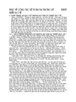
Figure b: peak power and critical threshold of power in
the therapeutic laser effects. Skin becomes saturated with
energy above the critical threshold and can only be
permeated at lower peak power. If power higher than 20
Watts is used, it can lead to photothermal effects which
give rise to skin burning.
By A. Vasta: therapeutic lasers….Marrapese Pub. .
Rome,1998.
The evolution towards pulse lasers is very favourable
from the therapeutic point of view and for the average
power, since laser penetration into the body is improved.
The total energy applied is therefore much higher than
with He-Ne laser.
4. Peak power: is the maximum power that a single laser
pulse can reach.
Above a certain value of between 10 and 20 W, the
increase in peak power exceeds the critical energy
threshold, saturates the superficial layer of the epidermal
tissue, and causes burning of the skin (thermic effect).
It can be harmful to the tissue.
The power of laser beams (both therapeutic and surgical)
is higher at the centre of the beam and falls off towards
the edges in a bell shaped curve (Gaussian).
Figure c: illustration of a typical Gaussian distribution of
laser beam power. The energy density is high at the
centre of the beam (surgical laser) and decreases
gradually towards the edges (therapeutic effects).
By: A.Vasta: Therapeutic lasers. Published by
Marrapese. Rome,1998.
The power weakens towards the edges of the beam with
lesser effects on the tissue hit.
This is also true in laser surgery (which explains less pain
and lower inflammation when surgical procedures are
done by laser instead of normal surgery).
This is called the “alfa effect”.
Therefore the “low power” part of the beam (in laser
therapy “cold”) is the reason that there is less pain and
inflammation in the injuries.
5. Quantity of radiation (energy density):
The quantity of radiation is the most important parameter
in low power laser therapy. It is even more important than
the type of laser used (visible or invisible, pulsed or
continuous) (see paragraph 3).
The quantity is measured in Joules (J) per area treated
2
2
(J/Area), or more commonly per cm (J/cm ).
It is important to make both types of calculation of the
amount, according to whether the laser has to be applied
to specific areas (trigger, acupuncture points, local areas,
etc.) or to larger tissue areas (sores, ulcerous areas, etc.).
One Joule of energy is equal to 1 Watt x second, i.e. it
represents the energy generated when 1 Watt (W) of
power radiates for 1 second (s):
J = W x sec.
The amount of radiation is the amount of energy that is
transmitted into the tissue.
Class IIIB lasers, emitting an average output power of 60
mW can release an amount of 2 J in 33 seconds; while a
class A laser, emitting a power of 3 mW, requires 11
minutes and 8 seconds to release the same amount (2 J).
This means that the class IIIB lasers have a distinct
advantage over the others as the treatment time is
significantly reduced.
If a GaAs laser is set up to work on low frequency single
pulse mode, its average power is very low.
In order to directly compare the various pulsed model
lasers, their output energy (Ju)/pulse and their
pulse/second (Hz) frequency must be noted by the
manufacturers.
It is very important to know if this energy is going to
be
2
transmitted through a small area (lets say 12 mm ) or
through an area that covers more than a few cm of tissue.
The average power of a single pulse laser depends on its
frequency (F), and the energy/pulse ratio (E/i), as shown
in the following table of a GaAs laser with different
frequencies:
Therefore in the treatment of areas like sores, ulcers, etc.
it is better to express the amount in the form of density of
2
energy in J/cm .
(The power in mW is calculated as Ei x F/1000).
Since 1 J = 1 Wsec, the amount of radiation D can be
calculated in the following manner:
P (W) x t (s)
2
D (J/cm ) = ------------------2
A (cm )
Where
2
D = amount of laser (J/cm )
P = power of laser transmitted to the tissue (W),
or the average power (mW/1000),
t = radiation time (s)
2
A = surface area treated (cm )
The treatment time necessary can also be calculated from
this:
2
2
D(J/cm ) x A (cm )
t (sec) = ----------------------------P(W)
In order to calculate the exposure time needed to treat a
certain tissue area (A), the average laser power must be
converted into Watts: e.g. laser power of 15 mW emits
15/1000 = 0.015 W.
For example, if a 10000 Hz pulsed laser emits 5 Ju/pulse,
its average power is 10000 x 5 / 1000 mW = 50 mW.
Generally single pulsed lasers are ineffective if the pulse
frequency is less than 1000 Hz.
For example, a laser with a pulse energy of 1 Ju and a
pulse frequency of 1 KHz (=1000 Hz) has an average
2
power of only 0.1 mW. If an area of cm 5x5 needs a
2
laser amount of 1 J/cm , the exposure time should be the
following:
DxA
t = -----------P
1 x 25
t = ------------ = 250000s
0.0001
D= amount required (J/cm2) ;
A= area treated (25 cm2);
P = average power (0.1 mW=0.0001W)
therefore t = 4167 minutes.
This shows that a laser with an average power of 0.1 mW
is not practical for laser therapy.
If 1J = 1Ws, then 1W= 1J/s.
It also shows that you at least need to know the average
power (or the pulse frequency and the power/pulse ratio)
of the laser in order to calculate the radiation amount
needed to provide effective treatment.
Therefore if a laser has 15 mW of power, it emits a laser
energy of 0.015 W = 0.015 J/s.
The following concepts are also important in order to
gain optimal therapeutic benefits in laser therapy:
In 10 sec the emission equals 10 x 0.015 = 0.15 J.
1) For best biostimulation effects (in treatment of
sores, burns, bruises, etc.) the radiation dose has
minimum and maximum limits. The optimal
amount is between these limits. If the amount is too
low, the treatment may not be effective, if the
amount is too high the treatment may be either
ineffective, or provoke negative effects.
2)
The biostimulating effect is cumulative: suitable,
repeated amounts given at relatively frequent
intervals give a cumulative effect. Small, repeated
amounts given at 1-7 day intervals provide as
powerful an effect as if the same amount of
radiation was given in one treatment session only.
The optimal weekly radiation amount for He-Ne laser
2
therapy seems to be about 1 J/cm .
With a laser that emits an average output power of 3 mW,
2
333 seconds/cm are necessary. If the average power is 60
2
mW, 16.5 seconds/cm is necessary.
For the best results on acupuncture points, the amount
recommended by the Soviet literature is for about 0.1
J/Acupuncture point.
With a laser that radiates an average output power of 3 or
60 mW, 33 or 1.65 seconds/AP point respectively would
be necessary.
INFORMATION ON THE MANUAL
This document provides valuable information regarding
the installation, set up and use of LIS 1050 .
It is a useful and essential reference guide for the user.
Read the contents of the manual carefully before
installing the equipment and keep it on hand at all times
for future reference.
It is of vital importance that you strictly adhere to the
recommendations contained within the manual in order to
avoid malfunction, which may cause damage to the
equipment and consequent annulment of the validity of
the warranty.
Furthermore, in order to obtain the highly efficient
technical service available from the manufacturer, it is
essential that any handling of the equipment be in
accordance with the instructions provided.
N.B. The Therapy Application Manual is available upon
request.
WRITING CONVENTIONS
Underlining - Certain sections of the manual have been
underlined in order to highlight their importance.
Notes
These contain important information and useful tips for
operating the equipment
CAUTION
The CAUTION message appears before operations,
which, if not correctly performed, may cause damage to
the machine and/or its accessories.
! WARNING !
This signals operations or situations, which, if unknown
to the operator, or incorrectly carried out, may harm the
operator.
WARRANTY
EME Srl guarantees the quality of its products for a
period of twelve months from the date of purchase, when
information contained in this manual regarding
installation, use and maintenance is strictly adhered to
and the warranty coupon is returned within 15 days of
purchase.
The guarantee covers the replacement of faulty parts.
The warranty does not however, include the replacement
of the equipment.
EME srl does not assume liability for malfunctioning or
damages resulting from:
–
–
–
–
–
–
–
Incorrect connection and installation
Incorrect use due to non-compliance with
instructions contained in this manual
Use of the machine in environmental conditions
which do not conform with those specified for the
product
Improper or inadequate maintenance
Unauthorised opening of the outer casing
Tampering or unauthorised modifications
Use of non-original accessories
EME Srl registered offices provide the warranty.
Should you need to return the goods then please note the
packing instructions as follows .
Enclose a copy of the purchasing receipt.
You should insure the postal package.
Before sending the machine back for suspected
malfunction, we recommend that first you carefully
consult sections regarding MAINTENANCE and
TROUBLESHOOTING of the manual, as a large part of
the problems and faults are usually due to inadequate
maintenance or small technical problems which can often
be easily solved by the user himself.
Particular attention has been paid to the design, easy
operation, function and safety of the equipment and the
final result is this modern, compact unit, which offers an
extremely logical operative sequence supported by a
clearly legible display.
A wide range of therapeutic applications, and guaranteed
patient and therapist safety ensure that LIS 1050
equipment is of the highest quality.
PRELIMINARY NOTES
UNPACKING
A simple call to our technical department may prove to be
the solution to the problem.
LIS 1050 equipment is specially packaged for transport in
a single pack complete with filling which has been
specifically studied for safe transportation and storage.
CAUTION
To remove the equipment from the pack, place the box on
a smooth, flat surface.
The customer is responsible for any damage caused by
incorrect packing of the equipment when returning it to
the manufacturer. We therefore recommend that you use
the original packing materials.
When re-packing the equipment for return to the
manufacturer, proceed as follows:
-
-
Unplug the machine and any connections, devices,
applicators etc.;
carefully clean and disinfect all parts of the
machine and accessories which have been in
contact with patients;
any equipment which the technical department
does not consider hygienic (Italian law
626/19.09.1994 on safety in the workplace) will
not be accepted;
disassemble accessories and any mechanical
supports;
use original box and packing materials;
enclose detailed information regarding the nature
of the problem in order to facilitate the technical
department’s intervention and save time on repair.
IN GENERAL
EME srl has recently developed a complete series of
apparatus, accessories and equipment, designed and
manufactured according to the highest standards of
quality, making use of the latest technology and fully
adhering to current directives and norms.
Open the top of the box and remove the polystyrene
filling.
Be very careful when removing the contents of the pack.
The unit and accessories are wrapped in transparent
sheets of polyethylene protection and contains the
following:
–
–
-
the User’s Manual
no. 1 mains power supply cable;
no. 2 spare fuses (see technical specifications);
no.2 pairs of safety goggles.
Check the contents of the package and should any of the
items be missing then contact your local authorized EME
srl dealer.
Save the original box and all the packing materials
in case you need to return the equipment to the
manufacturer or your dealer.
SETTING UP
Installation of the laser therapy equipment is fast and
simple.
If an external interlock safety circuit is required you must
provide a shielded, earthed duplex cable, minimum
diameter 0.6 mm, maximum length 20 m.
A one-way micro-switch is provided on the safety circuit
side which is normally turned off.
This circuit is an external safety device: it allows the laser
treatment to be suspended if a door is opened in the room
where the treatment is being applied.
If there is only one door in the room where the treatment
is being applied, the layout will be as follows:
! ATTENTION !
If you wish to install the external interlock circuit
use qualified technicians only
and provide the technician with the layout
of the room where the treatment is being applied.
If it is not installed correctly,
serious eye injury may result.
The following environmental conditions are ideal when
installing the unit:
- room temperature
- humidity level
from 10°C to 40°C;
from 10% to 80%
without condensation;
- avoid direct exposure to sunlight, chemical
products
and vibrations.
CAUTION
Do not use LIS 1050 equipment wherever
there is a risk of either the external or internal
parts of the unit becoming wet.
Fig. D
ELECTRICAL CONNECTION
If there is more than one door in the room where the
treatment is being applied, the layout will be as follows:
The power entry module can be found on the back of the
unit and consists of a three-pole socket for the cable set,
an extractible fuse box with two fuses (see technical
specifications) and the main switch. Insert the three-pole
plug of the cable set into the power entry module
correctly.
!WARNING!
Before plugging the cable set into the mains, check
to make sure the equipment has not undergone any
damage during transport and make sure the voltage
corresponds to that of the unit (see the rating plate on
the side of the unit).
Fig. E
!WARNING!
Fig. 1 : Interlock
The power supply to the unit is
VERY DANGEROUS!!
Make sure that the cable has been unplugged
from the mains supply before connecting or
disconnecting from the unit.
!WARNING!
For safety purposes the cable set is provided
with an earthed plug.
The equipment WILL NOT WORK WITHOUT IT!
Make sure that power supply socket has been earthed.
You can keep the safety contacts at a distance thanks to
the socket. You must use a 1-way micro-switch that is
normally turned off, for the safety interlock.
!WARNING!
The safety key works by cutting off both the invisible
laser emission, and the Led targeting power in red.
The equipment must only be connected
to power supply units that comply with
all safety directives in force.
When using an extension lead, make sure
that it has been earthed
Failure to comply with the above instructions
may lead to dangerous electrical discharge
causing machine damage and harm to persons.
LIGHTING OF THE DEVICE
When the Unit is switched on, the LCD display lights up
and LIS 1050 is ready for use .
The following will appear on the screen ( see fig. 2 ) :
CAUTION
If an extension lead is used with LIS 1050 and
other equipment, make sure that the total ampere
absorption of all the devices together
does not exceed that consented for that type of cable,
and in any case does not exceed 15A.
Once you have checked that installation and assembly
have been carried out according to instructions provided
up to this point in the manual, switch on the machine
making sure that the display screen is turned on correctly.
SAFETY KEY
The unit is supplied with an (INTERLOCK) safety key
comprising a DIN plug to plug into the DIN socket on the
back. (Fig.1)
Fig.2
Following that screen, another will be loaded in which the
user is asked to enter an access code.
This code has been set as default to
<START><STOP>< <START>
Press the buttons as indicated in the sequence for to type
the access code ( see fig. 3 ) .
All working parameters are handled and controlled in real
time by a sophisticated microprocessor electronic circuit
which clearly displays its functions accompanied by
acoustic signalling .
CONTROL PANEL
Fig.3
This code can not be modified by the user , and its taping
admits LIS 1050 to its functioning , by loading the main
page ( see Fig.4 ) .
The front panel of the unit, which comprises the controls
and signals, can be seen in fig. 1 with corresponding key.
You can choose from one of the four operating modes by
pressing the appropriate function key.
Fig.5 Control front panel
Fig.4
ACCESSORIES
The device can be used with the following accessories:
MLA1/25
MLA1/50
MLA1/100
Model
Probe with 1
laser diode
MLA1/500
(supplied)
MLA3/75
MLA3/150
MLA3/300
MLA5/125
MLA5/250
MLA5/500
MLA8/200
MLA8/400
MLA8/800
Probe with 3
laser diodes
(optional)
Probe with 5
laser diodes
(optional)
Probe with 8
laser diodes
(optional)
Total peak
power
25 W
50 W
100 W
500 W
75 W
150 W
300 W
125 W
250 W
500 W
200 W
400 W
800 W
Key:
1.
2.
3.
4.
5.
6.
7.
8.
Name of the unit
Graphic LCD display
Upper left function button
Lower left function button
UP selection button
DOWN selection button
OK confirm button
START button to start output
9. STOP /PREVIOUS PAGE function button
Buttons 3) and 4) take on the function that is on the
screen.
FRONT PANEL
DESCRIPTION OF THE EQUIPMENT
LIS 1050 equipment for laser therapy has a wellengineered control panel ideal for use in the specific field
of application for which it was designed.
The front panel can be seen in fig. 6 with its
corresponding key.
Fig. 6: Front panel
Key:
1 and 2 Normally closed safety contacts
3 Not connected
CONTRA - INDICATIONS
Key
1. Connector output
BACK PANEL
The back panel hosts the socket for safety key and the
integrated power board containing the power switch, the
fuse block, and the connector for the mains power cable
plug, as shown in Fig. 7.1 and Fig. 7.2 with its key .
Fig. 7.1 : Power board
1. Direct eye radiation: class 3B lasers are potentially
harmful to the retina – although retina damage is
extremely improbable. The special safety goggles
(supplied) must always be worn by both the patient
and the operator.
2. Pregnancy: the laser should not be used over a
pregnant woman’s uterus. It can be used on pregnant
women on condition that there is no radiation over the
abdomen.
3. Neoplasy: do not use the laser over primary or
secondary wounds that have not been diagnosed.
Laser treatment may be used to relieve pain in the
final stages of the illness. It should only be performed
with full patient consent.
4. Thyroid: laser must never be used over the thyroid.
5. Haemorrhages: indirect laser vaso-dilatation may
worsen the haemorrhaging.
6.
Immunosuppressive therapy: do not use laser
therapy on patients undergoing this type of
pharmacological treatment.
7. Treatment over the sympathetic nervous system,
the vagus nerve and the heart area in patients with
heart disease: laser therapy can significantly modify
neural functions and should not be used over these
areas of the body in patients with heart disease.
Key:
1. Fuse block
2. Bipolar ON/OFF power switch
3. Three pin plug for mains power
cable
CAUTION:
•
Photosensitive reactions: patients who use certain
types of medicine can display photosensitive
reactions. It is not fully understood how the
combination of laser and medicine trigger these
reactions. Patients who may be at risks for allergies,
or who have a history of these reactions, should first
be “tested” by applying treatment for a minimal time
period.
•
Means of attachment, metallic or plastic plates or
pacemakers CAN be used with lasers, and patients
with metallic and plastic implants, stitches, or with
pacemakers can safely avail of laser treatment.
Fig. 7.2 : Socket for safety key
HOW TO USE THE EQUIPMENT
This section provides important information and
instructions on how to make the best use of the LIS 1050
equipment for laser therapy.
All the control functions and the machine itself are
handled and co-ordinated by a microprocessor: apart from
making pre-memorised programmes available for
application, the microprocessor ensures that the machine
can be personalised and operated in a highly safe and
efficient manner.
Interfacing allows for the operator to communicate with
the unit by means of a large, clear graphic backlit liquid
crystal display screen (LCD) through which all
operational messages required by the operator, work
status during operation, and errors are visualised.
The following paragraphs illustrate the procedures to be
carried out and the technical specifications of the LIS
1050 .
They also deal with the different options available, from
the selection of a pre-memorised programme for use in
specific treatments as well as how to determine the
correct working parameters for “personalised”
application.
DESIGNATED USE
LIS 1050 equipment has been designed specifically for
use by professionals who have undergone training in laser
therapy and can guarantee total safety to their patients.
Different types of pain in different areas.
After having installed and correctly positioned the
machine as per the instructions described in the previous
sections and connecting the laser applicator correctly,
plug the machine into a 230Vac wall socket and switch
on using the ON/OFF main switch on the back panel of
the unit.
Once turned on, the LCD display lights up and LIS 1050
is ready for use (see fig. 2) .
Following that screen, another will be loaded in which the
user is asked to enter an access code ( see fig .3 ) .
Once you have taped this code , the main page has loaded
( see Fig.4 ) , and you can choose between four operative
modes by pressing its taste function .
ATTENTION
Please stop the treatment if any disturbance
occurs during its application.
SET-UP
This enables the basic settings to be memorised and saved
within the machine memory and will automatically be
called up each time the machine is turned on.
You can also set the language of the unit, prepare it for
correct operation and carry out the laser test .
Use the UP and DOWN buttons to choose the option.
Press the OK button to confirm ( see Fig.8 ) .
Inflammatory disorders of the tendons and soft tissues
(tendonitis, bursitis, enthesitis), insertional disorders,
superficial limb pain.
Assists in the treatment of ulcers and bedsores.
In scars and treatment of oedema.
Fig.8
BEST USE
DISPLAY
! WARNING !
It is important that the operator ensures the
machine’s correct electrical installation
before turning on the machine.
If you press on OK, the option will be highlighted and
can be selected and then set using the UP and DOWN
buttons.
If you press on OK again (or wait for a few seconds), the
item will no longer be highlighted and any modifications
made can be saved or cancelled.
At this point, save the required settings by pressing on the
SALVA function at the side: a window will appear noting
that the required settings were saved.
If you select the DISPLAY option, you access the
following screen (see fig. 9)
However, if you press on the ANNULLA function, the
settings will not be saved.
In both cases you return to the screen shown in fig. 8.
Fig.9
In order to memorise the settings that best suit the
visibility conditions of room, press the SALVA button.
Fig. 11
Otherwise press the ANNULLA button which will bring
you back to the previous page ( see fig. 8 ) .
Following this, return to the main menu, enter "direct
procedure" and then press START: the unit will start
emitting radiation in “CONTINUOUS” mode by default
and the icon showing progress of the treatment will be a
triangle with the vertex pointing right. .
PROBE
If the OK button is pressed on this function, the following
screen will appear ( see Fig.10 ) :
Alternatively, if you select the MANUAL or
AUTOMATIC emission modes, save the desired settings,
enter direct procedure and press START: now the unit is
working in “MANUAL” or “AUTOMATIC” mode
(according to the selection made) and goes into stand-by.
This is shown by the icon showing progress of the
treatment which is now in the shape of a little hand (fig.
13).
Fig. 10
You can select the following on this screen:
• The type of emission to supply treatment with
(continuous emission, manual emission,
automatic emission)
• The type of probe to use (see paragraph on
“accessories”)
• The area to treat
Fig. 12
“Continuous” emission is where the probe emits the
power set by the operator in a continuous manner.
“Manual” emission is where the probe supplies the power
set by the operator as long as the operator exerts pressure
on the metallic plate that acts as a contact sensor.
“Automatic” emission is where the probe emits the power
set by the operator after having made contact with the
skin in the area to treat.
Fig.13
This icon indicates that it is waiting for the operator to
press on the contacts of the TOUCH-SWITCH sensor.
When this is done the icon will change into a triangle
again with the vertex pointing towards the right. .
If you press on STOP, the icon will turn square shaped
again (see fig. 14).
Fig.16
The screens shown in figs. 15 and 16 are obtained by
repeatedly pressing the OK button.
Fig.14
If you press on EXIT , you return to the screen shown in
fig. 4.
This lets you deactivate or re-activate the warning beep.
It’s also possible to execute the formatting of the user
memory , that it’s the only memory usable for to save the
customized programs .
You can also to use the “Formatta Memoria” function fot
to cancel it completely .
NOTE
In order to avoid accidental deletion, you are asked to
confirm the operation.
Any time a different probe is used,
it must be set within this section.
NOTE
You must also enter the area of the part to be treated.
Fig.17
In the “Area” menu the surface area to be treated must be
entered.
The power emitted will be adjusted in inverse proportion
to the area.
If you press on the ANNULLA function, you return to the
screen shown in fig. 15 or fig. 16.
If you press on the FORMATTA function, a window will
appear which shows progress of the formatting operation
(see fig. 18).
MISCELLANEOUS
The same functioning logic as with the display settings
works with the following functions ( see fig. 15 ) .
Activate or turn off the acoustic warning signal.
Fig.18
and finally a screen that shows when the formatting
operation has finished (see fig. 19).
Fig.15
DIRECT PROCEDURE
This means you can create customised programmes on
the spot.
Fig.19
They cannot however be stored ( see Fig.21 ) .
If you press on the SALVA function ( see fig. 15 or
fig. 16 ), the settings selected will be saved and will come
up again every time the unit is turned on.
On the other hand, if you press the ANNULLA function ,
the settings selected will be not saved .
In both cases you return to the previous screen of fig. 8 .
LANGUAGE
The type of probe entered will also be noted.
To select the language you wish to view the messages and
commands :
•
Fig.21
If a channel is in use, you obviously cannot set a new
programme until it finishes.
select the language required using the UP and
DOWN buttons
confirm the language selected by pressing on OK
Before starting the therapy you can modify any of the
parameters: however, the modified programme cannot be
stored.
Press on the SAVE function to enable the new language
( see fig. 20 )
With UP and DOWN buttons you can choose from
among the parameters , by pressing the OK button it’s
possible to modify their values .
•
If you press on ANNULLA , the new language setting
will be cancelled.
In both cases you return to the screen shown in fig. 8.
N.B.: the parameters are highlighted in black if they are
being modified. You cannot modify other parameters or
exit the function if you don’t first confirm by pressing the
OK button , or wait a few seconds until the item is no
longer highlighted. .
The following parameters can be modified:
- FREQUENCY: the frequency emitted from the knob
is noted and the corresponding power calculated in mW;
Fig. 20
After a short wait while the new dictionary is loading, the
menu will appear in the selected language.
You can repeat the procedure at any time to change the
language.
PULSED: The percentage value that defines the
“Pulsed” mode is the percentage of active time compared
to the entire duration of the operative cycle (1 second).
So 100% means continuous activity, while 50% means
that the active stage and the following pause stage both
last for the same amount of time;
- TIME: expressed in minutes. It indicates the total time
that the therapy should take ; this tratment time is
calculated in relation to the probe used for the
therapeutical treatment emission .
LOADING PROGRAMMES
If a channel is in use, you obviously cannot set a new
programme on it until it finishes.
If you access this section, you can choose from the preset therapy programmes stored in the unit’s memory ( see
Fig. 22 ).
After pressing OK on the work program selected (for
example, acne) the following screen will appear (see fig.
24):
You cannot delete these programmes.
You can temporarily modify them but the modifications
will not be stored in the memory.
By pressing the OK button in the CARICA
PROGRAMMI menu ( see fig. 4 ) you enter in the
programs that areloaded in the main memory ( see
fig.22 ) .
Fig.24
Once the chosen treatment programme appears on the
display, press the START button to start it up.
APPLICATION OF THE THERAPY
Fig.22
By pressing the MEMORIA UTENTE button ( see Fig.
22 ), you select customised programmes that are stored in
the user memory nd created with the “Crea Programmi”
function ( see fig.23 ) .
Once you press the START button, a countdown will start
on the timer .
This is also noted by an arrow next to the channel (a
square indicates non active channels).
Fig.25
Fig.23
ATTENTION
In this case the MEMORIA UTENTE button is
highlighted , and this means that the visualized programs
are realtive to this memory area .
Please stop the treatment if any disturbance
occurs during its application.
If you press it again you will go back to Fig. 22 .
The user programs , that are customized by the operator
and are storable exclusively in the user memory , can’t be
renominated once has been created .
The stored programmes reflect the fruit of many years
experience supporting expert professional operators.
Appendix C shows a list of the programmes
available.
N.B.: the parameters are highlighted in black if they are
being modified. You cannot modify other parameters,
exit the function, or start the therapy if you don’t first
confirm by pressing the knob, or wait a few seconds until
it is no longer highlighted.
The count-down and the emission continue until:
a)
the set time finishes: when the system will
sound intermittent signal tones for a few
seconds.
Fig.26
b)
when the STOP button is pressed: the
emission cycle is paused ( see Fig. 27 )
WARNING
Laser radiation from the equipment is
inherently dangerous: always use safety goggles.
Do not look at the beam with your
naked eye or with any optical instrument.
Do not expose the beam unless it is being
strictly controlled; avoid exposing the eye
to direct or diffuse radiation.
Direct exposure to laser radiation for a fraction of a
second is not dangerous, however prolonged exposure
can be harmful.
The damage is directly proportional to the power emitted.
SETTING UP PROGRAMMES
Fig.27
–
-
the unit will take up again from the point where
it was interrupted when you press the START
button.
if you press the STOP button again, the emission
will be stopped completely ( see Fig.28 ) .
This function can only be used with the user’s memory as
it is the only memory available for storing new programs.
For to create a new program , you select the CREA
PROGRAMMI menu with UP and DOWN buttons , so
you press the OK button to confirm the choice ; it appears
this page ( see fig. 29 ) :
Fig.29
Fig.28
As previously noted, the LIS 1050 is an IR diode laser
beam designed and manufactured in full accordance with
national and international safety standards (see
Appendix).
It is classified as a CLASS III B LASER: This equipment
should always be used with caution in order to reduce any
risk (although the risk is contained due to the specific
power from IR diode radiation) that may arise from a
laser source which is inherently distinguished by monochromaticity, collimation, coherency and brilliance.
By pressing on ESCI , you return to the page of fig. 8 .
On the other hand , by pressing the OK button on the
highlighted menu , it appears this page ( see Fig.30 ) :
Fig.30
From here you can modify:
•
•
•
•
the frequency
the pulse percentage
the treatment duration
and the name to give the program if desired
If you press on ESCI , you cancel the renomination of the
customized program .
On the other hand , by pressing on SALVA , the
customized program has renommed and has saved in the
user memory .
Use the UP and DOWN buttons to move the cursor until
you get the menu you want to modify, then press OK on
the menu selected.
MAINTENANCE
If you press the SALVA function, the customised features
will be linked to the program which will be stored in the
user’s memory with the name assigned.
The LIS 1050 machine for laser therapy does not require
any particular maintenance operations.
If you press on the ESCI function, the modifications will
not be saved and you return to the screen shown in fig.
29.
!WARNING!
If you only want to modify the 3 parameters and keep the
name, just press on the SAVE function after changing the
settings.
Otherwise, once this is done, you can rename the program
by pressing OK on the name as follows:
1. move the cursor to the name field using the
UP and DOWN buttons (see fig. 30)
2. press on OK and the following screen will
appear (see fig. 31)
Before carrying out any maintenance or
cleaning procedures on the equipment,
MAKE SURE TO TURN OFF
the unit with the switch on the rear panel
and unplug it from the mains.
When cleaning the outer part of the equipment, make sure
to use a soft, clean cloth dampened with luke-warm water
or very mild non inflammable detergents.
The front panel can be cleaned in the same way.
Contact authorised dealers of EME srl for information
regarding original spare parts or components.
CAUTION
Fig.31
3. press OK on the character indicated by the
cursor: the character selected will be
highlighted and can therefore be modified
4. select the character required using the UP
and DOWN buttons
5. confirm the character chosen by pressing on
OK. At this point the highlighting will
disappear and the character can no longer be
modified
6. take the cursor to the next character using
the UP and DOWN buttons and repeat
operations 1 to 5
7. When finished typing the name, press on OK
to confirm the new name given to the
program (see fig. 31).
8. the screen shown in fig. 30 will appear with
the new name assigned to the program
When cleaning the outer part of the equipment,
do not use diluents, detergents, acid solutions, abrasive or
aggressive solutions, or inflammable substances. Use of
any of the above mentioned substances or improper use
of the accessories will cause irreparable damage to the
equipment and the guarantee will be no longer valid.
Do not spray or pour liquid onto the external parts of the
equipment, or into the air holes on the casing.
Do not immerse the unit in water.
After cleaning the external part of the equipment, make
sure to dry it perfectly before turning on the unit.
The unit must under no circumstances be opened or
dismantled in order to clean or check inner parts – LIS
1050 equipment does not require cleaning of inner parts
and in all cases, only specialised technicians or EME srl
authorised personnel should carry out such operations.
CAUTION
Check the integrity of the cable set
and the cables connecting the handpiece/applicator at
frequent intervals: they should never be damaged or
display signs of wear and tear
TECHNICAL PROBLEMS
LIS 1050 laser-therapy equipment has been designed and
manufactured using highly advanced technology and first
class components for reliable and efficient performance.
However, should you meet with any operational
problems, we recommended that you consult the
following guide before contacting any of our authorised
service centres.
! WARNING !
DO NOT OPEN LIS 1050 equipment as
HIGH VOLTAGE ELECTRICITY
is present and may prove VERY DANGEROUS.
! WARNING !
DO NOT OPEN the handpiece/applicator :
this will cause damage to the accessories
and cause the warranty to lapse
CAUTION
Only EME srl authorised technicians may carry out
service on the internal parts of the equipment.
The equipment contains an IR LASER SOURCE
which emits dangerous radiation
For repairs and further information, contact EME srl –
MEDICAL Italia or authorised service centres.
If any of the following situations occur, disconnect the
machine and contact EME srl authorised service centres:
-the cable set or rear supply panel show signs of wear and
tear or are damaged;
-liquid has entered the equipment;
-the equipment has been exposed to rain.
ELECTROMAGNETIC INTERFERENCE
LIS 1050 laser-therapy equipment has been designed and
manufactured according to the ELECTROMAGNETIC
COMPATIBILITY DIRECTIVE 89/336/CEE with the
aim of providing adequate protection from harmful
interference when installed in homes and health
establishments.
All the necessary measures and tests were carried out at
the EME srl Testing and Measure Laboratory (LPMC)
and in external specialised laboratories.
The customer, upon prior request, may view the reports
relative to EMC measures within the company.
The LIS 1050 laser therapy equipment does not generate
significant radio frequency energy and is adequately
immune to radiated electromagnetic fields.
Therefore it does not detrimentally interfere with radioelectric communications, electro-medical equipment for
monitoring, diagnosis, therapy and surgery, office
electronic devices such as computers, printers,
photocopiers, fax machines, etc. or any electric or
electronic equipment used in these environments, as long
as
said
equipment
complies
with
the
ELECTROMAGNETIC COMPATIBILITY directive.
In any case, in order to avoid any interference problems,
we recommend that you operate the therapy equipment
far enough away from critical equipment for monitoring
vital patient functions, and that you be careful when
applying therapy to patients with pacemakers.
TROUBLESHOOTING CHART
PROBLEM
POSSIBLE CAUSE
LCD display on front panel
Plug incorrectly inserted into socket.
does not light up
SOLUTION
Check that the socket is working
correctly.
Power cable incorrectly inserted into the Insert the plug correctly into the socket.
connector on the rear of the unit. Cable Replace the worn out or damaged power
is worn, damaged or blocked.
cable.
Unit does not function
The switch on the rear of the unit is
turned off. Fuses missing, blown or
blocked.
Turn on the switch. Replace any
missing, blown or interrupted fuses.
Electronic control circuit does not work. Contact EME srl Service centre.
No power reaching the socket.
LCD display on front panel Presence of faulty components on
does not light up
electronic control card
Contact EME srl Service centre
Some of the buttons on the
Faulty keys or buttons. Electronic
front control panel do not
control circuit malfunction
function correctly
Contact EME srl Service centre
The unit lights up but does
not emit energy
Parameters not set correctly.
Laser source does not function or has
run out.
Check that the parameters have been set
correctly.
Check laser source emissionis operating.
Faulty components on electronic control
Contact EME srl Service centre
circuit. Faulty supply on laser circuit.
The unit functions
normally but with a
significant decrease in
efficiency of treatment.
Faulty or depleted laser source.
Possible break down in power generator
circuit of the unit..
The equipment starts up, or
No safety key or the interlock circuit is
seems to work normally,
open.
but there is no emission.
Contact EME srl Service centre
Insert the DIN safety key into the back
socket or ensure the Smart-Card is
inserted, reset the safety conditions.
TECHNICAL SPECIFICATIONS
LIS 1050
230 Vac, 50-60Hz, ±10%
Mains voltage:
115 Vac, 50-60Hz, ±10%
Max. Power absorption:
15 VA
Double fuse protection:
230 Vac
250 mA Rit. 5 x 20 mm
115 Vac
500 mA Rit. 5 x 20 mm
Interlock socket/Safety key (contacts normally closed)
3 contact DIN socket
Backlit LCD Display, to visualise and control operating parameters:
graphic 240 x 64 pixel
Programmable treatment time:
up to 99 minutes
Diode Laser wave length emission
905 nm
Classification
III B
EMP
5032.06 J . m-2
LEA
77.1 mW (class limit 3B)
Divergence
107 mrad
DNRO (direct light)
2.89 metres
DNRO (scattered light)
0.00 metres
Sensor for detecting IR radiation of the external handpiece
on the front
Programmable pulse frequency
200 - 10000 Hz
Pulse duration
100 nsec.
Automatic scanning
5 frequencies per decade
Pulsed mode
10 - 100%
Peak power for single diode
Total peak power
depends on probe-applicator
25 W
(See accessories)
Output channels
1
Stored protocols
20
Storable protocols
10
Table container in plastic,
external size (width x height x depth)
Unit body weight
39 x 14 x 30 cm
3,25 Kg
* on demand
23 / 28
LIS 1050 - rev.0 - 05/ 02/ 08
APPEN D I C
ES Appendix A
ENVIRONMENTAL CONSIDERATIONS
LIS 1050 laser therapy equipment has been designed and manufactured to have minimal negative environmental impact,
in line with its operational and safety requirements.
Rigorous standards were followed in order to minimise the amount of waste, use of toxic materials, noise, non-required
radiation and energy consumption.
In accordance with careful research, the unit has been designed to optimise power consumption in keeping with energy
saving principles.
This symbol means that the product should not be disposed of as domestic waste.
The user must dispose of scrap equipment by taking it to a recognised electrical and electronic recycling centre.
24 / 28
LIS 1050 - rev.0 - 05/ 02/ 08
Appendix B
LABELS
Label with the device specifications
(attached to the back of the device)
Label showing devices sensitive to electrostatic charges,
placed near the serial connection connector
Label on the laser hand-piece showing its properties
25 / 28
LIS 1050 - rev.0 - 05/ 02/ 08