Nghiên cứu hiện tượng chuyển pha trong vùng hoạt lò phản ứng
Bạn đang xem bản rút gọn của tài liệu. Xem và tải ngay bản đầy đủ của tài liệu tại đây (3.97 MB, 113 trang )
BỘ GIÁO DỤC VÀ ĐÀO TẠO
TRƯỜNG ĐẠI HỌC BÁCH KHOA HÀ NỘI
HOÀNG MINH GIANG
NGHIÊN CỨU HIỆN TƯỢNG CHUYỂN PHA TRONG VÙNG HOẠT
LÒ PHẢN ỨNG
Hà Nội - 2016
9IO£-Ị0N?H
OỎH 03 IS NẸLL MỴ Nỹm
8010171739 :ọs
ĐMỌ1XVH3 3ỎH 03 •qu?ẵn usẤniỊO
DN.n NỴHd Ọ1
XVOH DNJXA ĐNOMX VHd NẸAÍ1XD ONQ.nX NỆIH OỢ3 MẸĨHOM
OMVIO IIVIIV OMVOH
IỘM VH VOI IM II3YÍI 30II IV CI 3YỌ.1MI
OVX OVQ VA 3íìa OVIĐ Oe
LỜI CAM ĐOAN
Tôi xin cam đoan luận án là công trình nghiên cứu của bản thân tôi dưới
sự hướng dẫn của tập thể giáo viên hướng dẫn.
Các kết quả nêu trong luận án là trung thực, không sao chép của bất kỳ
công trình nào và chưa từng được công bố trong bất kỳ công trình nào khác.
Hà Nội, ngày 27 tháng 4 năm 2016
NGHIÊN CỨU SINH
HOÀNG MINH GIANG Hướng dẫn 2
Hướng dẫn 1
PGS. NGUYỄN PHÚ KHÁNH
TS. TRẦN CHÍ THÀNH
3
LỜI CẢM ƠN
Trước hết, tôi xin bày tỏ lòng kính trọng và biết ơn tới: PGS Nguyễn Phú
Khánh và TS Trần Chí Thành, những người thày đã trực tiếp hướng dẫn, giúp đỡ
tôi trong quá trình học tập và thực hiện luận án.
Tôi xin chân thành cảm ơn các thày cô tại Bộ môn Kỹ thuật Hàng không
và Vũ trụ, Viện Cơ khí Động lực; cảm ơn TS Lê Văn Hồng, Viện Năng lượng
Nguyên tử Việt Nam, chủ nhiệm đề tài độc lập cấp nhà nước (mã số
ĐTĐL.2011-G/82) “Nghiên cứu, phân tích, đánh giá và so sánh hệ thống công
nghệ nhà máy điện hạt nhân dùng lò VVER-1000 giữa các loại AES-91, AES- 92
và AES-2006”, các đồng nghiệp Hoàng Tân Hưng, Trung tâm An toàn hạt nhân,
Nguyễn Hữu Tiệp, Trung tâm Năng lượng hạt nhân, Viện Khoa học và Kỹ thuật
hạt nhân đã giúp đỡ, tạo điều kiện để tôi có thể hoàn thành luận án này.
Tôi cũng xin trân trọng cảm ơn Ban lãnh đạo Viện Khoa học và Kỹ thuật
hạt nhân, Viện đào tạo Sau đại học của Trường Đại học Bách Khoa Hà Nội đã cử
tôi đi đào tạo cũng như tạo điều kiện thuận lợi trong quá trình thực hiện luận án.
Hà nội ngày 27/4/2016
Nghiên cứu sinh
STUDY ON PHASE CHANGE IN THE CORE OF
NUCLEAR REACTOR
Hoàng Minh Giang
4
5
Abbreviations and Nomenclature
Abbreviations
VVER
VVER-1200/V491
VVER-1000/V392
VINATOM
TSO
DID
PWR
SAR
NRA
RIAs
LOFAs
LOCAs
DNB
DNBR
Castellana
EPRI
BM ENTEK
RBMK-1000
PSBT
CTF
RELAP5
COBRA-TF
RELAP-3D
MARS-3D
Belene
Ansys CFX
CFX
PARCS
ITT
0D, 1D, 2D
CHF TH
RANS
A Type of Pressurized Water Reactor developed by Russia
A type of Russia reactor with capability of 1200 MWe
A type of Russia reactor with capability of 1000 MWe
Vietnam Atomic Energy Institute
Technical Support Organization
Defend in depth policy in nuclear power plant design
Pressurized Water Reactor
Safety Analysis Report of nuclear power plant
Nuclear Regulatory Authority
Reactivity insertion accident
Loss of coolant flow
Loss of coolant accident
Departure of nucleate boiling
Departure of nucleate boiling ratio
The 4 x 4 square rod bundle test for fuel rod in Columbia University
(USA)
Electric Power Research Institute
The BM Facility at the Research and Development Institute of Power
Engineering (RDIPE; a.k.a., ENTEK and NIKIET) models the forced
circulation circuit of RBMK type reactors
A type of Russia reactor of 1000 MWe with transliteration of Russian
characters for graphite-moderated boiling-water-cooled channel-type
reactor
OECD/NRC Benchmark based on Nuclear Power Engineering Corporation
(NUPEC, Japan) PWR sub channel and bundle tests A version of COBRATF improved by Pennsylvania State University (USA)
System code developed by Information Systems Laboratories, Inc.
Rockville, Maryland Idaho Falls, Idaho
Coolant-Boiling in Rod Arrays—Two Fluids (COBRA-TF) is a Thermal
Hydraulic (T/H) simulation code designed for Light Water Reactor (LWR)
vessel analysis developed by Pacific Northwest Laboratory
Newest version of RELAP5 with coupling with COBRA-TF
Newest version of MARS with coupling with COBRA-TF
A site for nuclear power plant project in Bulgaria
A Computational Fluid Dynamics developed by Ansys
Same as Ansys CFX
A code for neutron kinetic calculation
interface tracking technique
Dimension of spatial averaging
Critical Heat Flux
Thermal hydraulics
Reynolds-averaged Navier-Stokes Simulation
LES
MSLB
PTS
CFD
DI
FI
SI
U-RANS
T-RANS
meso scale
ECCS system
LBLOCAs
SBO
SG
SG PHRS
HA-2
HA-1
PCT
DBA
MCPL
LOOP
DG
SAR SG
OECD/NRC BFBT
acrit
Large Eddy Simulation Main steam line break Pressurize Thermal
shock Computational Fluid Dynamics Deterministic Interface Filtered
Interface Statistical Interface Unsteady flow Transient flow
The spatial scale with size around 1mm and less simulated with RANS
Emergency Core Cooling System
Large break for loss of coolant accident
Station black out
Steam Generator
Passive Heat Removal through Steam Generator
Secondary stage of Hydro accumulators
First stage of Hydro accumulators
Peaking temperature of cladding
Design Base Accident
Main Coolant Pipe line
Loss of offsite power
Diesel Generator
SG Active Heat Removal System
UPEC BWR Full-size Fine-mesh Bundle Test (BFBT) Benchmark
Void fraction corresponding with critical heat flux correlation
Nomenclature
a
^mtscv
A1"
■rtint,shl
A'” , rMnt,shv
As
Ax
Cpl
Cpv
G
h
Sub-cooled vapor interfacial area per unit volume (m-1)
Super-heated liquid interfacial area per unit volume (m-1)
Super-heated vapor interfacial area per unit volume (m-1)
Conductor surface area in mesh cell (m2)
Mesh-cell area, X normal (m2)
Liquid specific heat, constant pressure (J/kg.K)
Vapor specific heat, constant pressure (J/kg.K)
Mixing mass flux (kg/m2.s)
g,sat
int,scl
h
int,scv
h
int,shl
h
int,shv
hc
hl*
Vapor saturation enthalpy (J/kg)
Sub-cooled liquid interface heat transfer coefficient
2
(W/m
.K) vapor interface heat transfer coefficient
Sub-cooled
2
(W/m
.K)
Super-heated
liquid interface heat transfer coefficient
2
(W/m
.K)
Super-heated vapor interface heat transfer coefficient
(W/m2.K)
Chen correlation heat transfer coefficient (W/m2.K)
Liquid enthalpy (J/kg)
h
l,sat
g
h
/
h
ig
mr
m™
m
Plk
Liquid saturation enthalpy (J/kg)
Vapor enthalpy (J/kg)
Vapor interface heat transfer coefficient (W/m3.K)
Q
Wall heat transfer to liquid (W)
Wall heat transfer to liquid for convection (W)
Wall heat transfer to liquid for vaporization (W)
Vapor temperature (K)
Saturated temperature (K)
Critical heat flux temperature (K)
h
h
wf
Qconv
QW
ift Qboil
T
T
gS
r-J^
T
crit
Tl, Tf
rb
«ki
a
kiEQ
PTP
Pki
Pl
Pv
P' P m
pî 5 5
Liquid interface heat transfer coefficient (W/m3.K)
Mass exchange due to drift model (kg/s)
Mass exchange of phase k (kg/m2.s)
Density of liquid (kg/m3)
Liquid temperature (K)
Bubble diameter (m)
Void fraction of phase k induced by sub channel i
Equilibrium quality void fraction
Two phase turbulent mixing coefficient
Density of phase k in sub channel i (kg/m3)
Liquid density (kg/m3)
Vapor density (kg/m3)
Mixing density (kg/m3)
Volumetric mass flow rate (kg/m3.s)
r
1
hgw
Vapor generation from near wall (kg/m3.s)
Total Vapor Generation (kg/m3.s)
AX
a
li
P
Mesh-cell axial height (m)
Surface tension (N/m)
Fluid viscosity (Pa.s)
Pressure (Pa)
r’’
Tw
Evaporation rate (kg/m2.s)
Wall surface temperature (K)
Tchf ,Tcrit
Re
Critical heat flux temperature (K)
Reynolds number
Pr
Nu
n
k ,
l ^i
hv
hnb
Prandtl number
Nusselt number
Wall nucleation site density (m-2)
Liquid thermal conductivity (W/m.K)
Vapor enthalpy (J/kg)
Nucleate-boiling heat transfer coefficient
2
(W/m
Liquid.K)
enthalpy (J/kg)
h
l
g
h
fc
h
f
h
c
h
g
FChen
f
Dh
Cp
Ax
As
Vapor saturation enthalpy (J/kg)
Forced-convective heat transfer coefficient
(W/m2.K
Liquid saturation enthalpy (J/kg)
Chen correlation heat transfer coefficient
(W/m2.K)
Gravitational acceleration (m/s2)
Chen Reynolds number factor
Bubble detachment frequency (s-1)
Hydraulic diameter (m)
Specific heat, constant pressure (J/kg.K)
Fo
Mesh-cell area, X normal (m2)
Conductor surface area in mesh cell (m2)
Mesh-cell axial height (m)
Inverse Martinelli factor
Liquid density (kg/m3)
Fourier number
Pa
P
a ,r
aa
Rw
Rw
Rq
Re'
Rc
dp
Vapor density (kg/m3)
Mixing density (kg/m3)
Void fraction
Volumetric heat transfer from the wall (W/m3)
Total wall heat flux (W/m2)
Quenching heat flux (W/m2)
Evaporative heat flux (W/m2)
Convective heat flux (W/m2)
Local mean bubble diameter (m)
1
Saturation temperature (K)
Liquid temperature (K)
Mesh-cell area of phase k (m2)
AX
XTT
PI
T
sat
Ti
sk
Schen
Qi
G
^2
Chen suppression factor
Heat transfer per volumetric unit (W/m3)
Mixing mass flux (kg/m3.s)
Area influence factors
List of Tables
List of Figures
Overview
Phase change in the nuclear reactor core is related to safety criteria such as Departure of
Nucleate Boiling (DNB) during normal and transient conditions. So that, a lot of computer
codes with verification and validation against experiment are used to investigation of thermal
hydraulics behavior of vertical boiling flow in core channel with system and component scales.
Until now, even many studies on boiling flow are implemented in CFD scale codes, but their
utilization to specific nuclear reactor is not yet applied. Thus, the utilization of many codes
including CFD scale (Ansys CFX) to investigate void fraction in hot channel of VVER1000/V392 reactor core is studied in this work. Due to VVER-1000/V392 nuclear reactor is a
candidate for Ninh Thuan 1 nuclear power project, so that the understanding of VVER’s
reactor technologies including research works of this thesis is important to develop
competence of nuclear safety in Vietnam.
In this thesis, the numerical simulation is used to investigate boiling flow in the core channel
of VVER-1000/V392 reactor with verification and validation against experiment with similar
Pressurized Water Reactor conditions.
The thesis includes four chapters together a conclusion in the last. Chapter 1 mentions about
introduction that leads to motivation of this study. Chapter 2 presents the methodology related
to multi scale analysis along with the code theories at different scale for RELAP5, CTF and
Ansys CFX with focus on phase change models. The verification and assessment of modeling
used in these codes versus experiment data are presented in chapter 3. The system simulation
results are compared with those in SAR documents. The assessment of CTF code is
implemented by simulation BM ENTEK experiment tests which is an International Standard
Benchmark to investigate boiling flow through Russian fuel bundle of RBMK reactor. The
meso scale code Ansys CFX is verified with PSBT single sub channel which is also an
International Standard Benchmark as well. Chapter 4 presents the simulation of VVER1000/V392 by three scales with system, component and CFD codes corresponding with
RELAP5, CTF and Ansys CFX, respectively. Void fraction in hot channel of the core is
predicted by utilization of CTF and Ansys CFX codes.
It is summarized several main contributions from the thesis as following:
■ It is proposed a reality of best estimate approach in void fraction prediction by
utilization of multi codes and multi scale including MCNP5, RELAP5, and CTF for
analysis of void fraction behavior in the core during transient.
■ It is established a procedure of utilization of CTF and Ansys CFX for improvement of
void fraction prediction as following: (a) at sub cooled region, corresponding with
small bubble flow regime, Ansys CFX results is used; (b) in saturated boiling region,
CTF and Ansys CFX void fraction curves along the channel is used as upper bound and
lower bound to predict void fraction in the core.
It is found that, in saturated boiling region, the wall boiling model built in
Ansys CFX is incorrectly partitioned heat flux to corresponding parts in
convective, quenching and evaporative. This issue causes Ansys CFX gives
under prediction of void fraction in saturated boiling region. It is proposed a
calibration for bubble departure diameter and maximum area fraction to
13
improve void fraction prediction by Ansys CFX in saturated region.
14
Chapter 1. Introduction to research work
1.1
Status of nuclear power in the World and Vietnam
Nuclear technology uses the energy released by splitting the atoms of certain elements. After
Second World War, nuclear technology turned to peaceful purposes of nuclear fission for power
generation. Today, as updated in February 2015 [46], the world produces as much electricity
from nuclear energy as it did from all sources combined in the early years of nuclear power. Civil
nuclear power now can boast over 16,000 reactor years of experience and supplies almost 11.5%
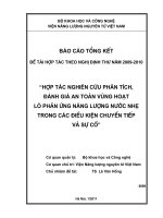
of global electricity needs. The 31 countries host over 435 commercial nuclear power reactors
with a total installed capacity of over 375,000 MWe as illustrated in Figure 1.1. About 70 further
nuclear power reactors are under construction, equivalent to 20% of existing capacity, while over
160 are firmly planned, and equivalent to half of present capacity.
WORLD NUCLEAR
/AUOCIATION
Nuclear Generation by Country 2013
0
50
100
TWh
150
200
250
300
USA France
Russia South
Korea China
Canada Germany
Ukraine UK
Sweden Spain
Belgium India
Czech Republic
Switzerland
Finland Slovakia
Hungary Japan
Brazil South
Africa Bulgaria
Mexico Romania
Argentina
Slovenia
Pakistan Iran
Netherlands
Armenia
Source: IAEA PRIS Database
Figure 1.1 Nuclear power generation by country in 2013 (source [46])
After Fukushima accident in 2011, it is needed to improve performance from existing nuclear
reactor safety, so that stress test is implemented for every reactor to ensure that it can stand
with design extension conditions as it occurred in Fukushima.
Nuclear power program in Vietnam was confirmed by National Assembly Decision on
November 25, 2009 with a plan to build four nuclear power units. Russian VVER technology
was selected for the first site and the VVER-1200/V491 and VVER-1000/V392 nuclear reactors
were considered as the candidates. In parallel with capacity building for nuclearpower
infrastructure, Vietnam Atomic Energy Institute (VINATOM) has been assigned to develop
technical competence of nuclear safety and, in future, it will become a main Technical Support
Organization (TSO) for nuclear safety in Vietnam.
1.2
Brief overview of nuclear safety
In any nuclear reactor, nuclear safety includes three primitive principals related to all operational
conditions: (a) control of reactivity, (b) heat removal from the core to ultimate heat sink and (c)
confinement of fission products in case of accident occurrence. Requirements of nuclear safety
enforce the utilization of defend in depth (DID) policy in nuclear power plant design. In general,
defense in depth policy is implemented by multiple levels of protection (Table 1.1) and
protection barriers
Table 1.1 Multiple levels ofprotection from DID approach (source [45])
Levels
Level 1
Objective
Prevention of abnormal operation and
failures
Level 2
Control of abnormal operation and
detection of failures
Level 3
Control of accidents within the design
basis
Control of severe plant conditions,
Level 4
Level 5
including prevention of accident
progression and mitigation of the
consequences of severe accidents
Mitigation of radiological consequences
of significant release of radioactive
materials
Essential Mean
Conservative design and high
quality in construction and
operation
Control, limit & protection
systems and other surveillance
feature
Engineered safety features and
accident procedures
Complementary measures and
accident managements
Off-site emergency response
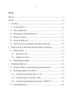
For PWR reactors at power operation, the barriers confining the fission products are typically:
(a) fuel matrix, (b) fuel cladding, (c) boundary of the reactor coolant system, (d) containment
system as shown in Figure 1.2. The nuclear utility owner must provide and demonstrate
that their technical plan design is satisfied for the safety requirements through safety
analysis report (SAR) which is reviewed and approved by nuclear regulatory authorities
(NRA) and independent TSO. All main issues, related to nuclear safety during plant life
time, are mentioned in SAR as illustrated in Table 1.2. Nuclear safety covers a wide
range of issues related to the plant including external hazards such as seismic, tsunami,
flooding... and internal hazard resulted from failure of structures, systems and
components together with human factor that are important to safety. In chapter 15 of
SAR, thermal hydraulics safety analysis is performed by simulation of different
categories of postulated transient and design base accident such as reactivity insertion
accident (RIAs), loss of coolant flow (LOFAs) and loss of coolant accident (LOCAs).
The main system and other connected systems including reactor coolant system (primary
system), secondary system are modeled by system code that can present the response of
safety systems to protect and bring nuclear reactor to safety condition.
Table 1.2 Content of Safety Analysis Reports (source [45])
Contents of Safety Analysis Reports
Chapter 1 - Introduction and General Description of Plant
Chapter 2 - Site Characteristics
Chapter 3 - Design of Structures, Components, Equipment, and Systems
Chapter 4 - Reactor
Chapter 5 - Reactor Coolant System and Connected Systems
Chapter 6 - Engineered Safety Features
Chapter 7 - Instrumentation and Controls
Chapter 8 - Electric Power
Chapter 9 - Auxiliary Systems
Chapter 10 - Steam and Power Conversion System
Chapter 11 - Radioactive Waste Management
Chapter 12 - Radiation Protection
Chapter 13 - Conduct of Operations
Chapter 14 - Initial Test Program and ITAAC-Design Certification
Chapter 15 - Accident Analysis
Chapter 16 - Technical Specifications
Chapter 17 - Quality Assurance
Chapter 18 - Human Factors Engineering
Chapter 19 - PSA and Severe Accidents
1.3
Core thermal hydraulics safety analysis in transient
condition
It is shown that the second barrier plays a very important role due to the fact that it protects
fission product in fuel rod from release to primary system. Therefore, the peaking cladding
temperature in transient and accident conditions must be satisfied specific acceptance criteria.
The acceptance criteria introduced by IAEA for transient condition in [21] is briefly formulated
as below:
(1) The probability of a boiling crisis anywhere in the core is low. This criterion is typically
expressed by the requirement that there is a 95% probability at the 95% confidence level
that the fuel rod does not experience a departure from nucleate boiling (DNB). The DNB
correlation used in the analysis needs to be based on experimental data that are relevant to
the particular core cooling conditions and fuel design.
(2) The pressure in the reactor coolant and main steam systems is maintained below a
prescribed value (typically 110% of the design pressure).
(3) There is no fuel melting anywhere in the core.
Length:
Fui-Ipellets
350
Rod
Pellet
Diameter:10mm
8mm
(Fuel
Pellet)
1st Barrier
bni« ■
stout
nd
~
270Assembly
Fuel Rods
Fuel
Assemblies
Rod)
Core
press
(Reactor
coolant
2(Fuel
Barrier
3rd bpundary)
Barrier
(Containment)
4th Barrier
Figure 1.2 Multiple physical barriers in DID policy (source [45])
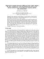
Based on the first criteria, core thermal hydraulics is related to boiling crisis during transient
condition. As mentioned in [31], the relation between heat flux from the wall and temperature
difference from wall and fluid for pool boiling heat transfer is illustrated in Figure 1.3. The point
“C” in Figure 1.3 is called burnout point due to departure of nucleate boiling (DNB) reached.
Thus, if heat flux from the wall increases to reach the burnout point (or also called DNB point)
and results in a numerous of bubbles which begin to coalesce and clump near heating surface (the
vapor covering the surface acts as a heat insulator). The blanket of vapor covering heating
surface limits heat transfer from wall to liquid and makes cladding temperature higher that lead
to violate acceptance criteria. This is known as partial nucleate boiling and must be avoid or must
be limited as the first criteria mentioned above in nuclear reactor during normal and transient
operation condition, respectively. As known in Figure 1.3, if heat flux reaches the burnout point,
heat transfer mode is unstable in transition from nucleate boiling to film boiling with
corresponding increase in wall temperature. Thus, the boiling crisis, in which cladding
temperature increases dramatically, corresponds to a sudden drop in heat transfer coefficient
from wall due to change boiling mechanism from nucleate boiling to film boiling. The boiling
crisis is presented by many names such as burnout, critical heat flux and DNB. The boiling crisis
in flowing coolant is more complicated than pool boiling due to added effects of forced
convection and bubbles clouding that tend to cover heating surface.
Single-phase
convection
1
0
Nucleate
boiling
boiling
film
Partial
boiling
Film
T.-T, rc]
Figure 1.3 Heal flux versus temperature difference for pool boiling heat transfers (source [31])
The boiling crisis in coolant flow is closely related to flow pattern and void fraction. In
[25], it is mentioned about two typical phenomenon of interest in nuclear safety as
presented in Figure 1.4.
Figure 1.4 Types of boiling flow crisis (source [25])
The left picture in Figure 1.4 shows the sub cooled or low quality DNB that is caused from
detachment of bubble from boundary layer. The picture in the right of Figure 1.4 shows the
burnout at high quality region that is caused from the liquid film covering heating surface
becomes “dry out”. The determination of critical heat flux at which DNB occurs is
verycomplicated due to the fact that it depends on many factors such as channel sharp, surface
condition, physical properties of the coolant and flow conditions. The most popular correlation
that ensures critical heat flux not exceeded during core operation is DNB ratio. It is defined by
the minimum ratio of the critical heat flux to the heat flux achieved in the core:
D N B R = q°NB (z)
(1.1)
Q (z)
For the PWR, the DNBR > 1.3 for insurance of DNB not occurred. Figure 1.5 shows the DNBR
along axial channel in the uniform core.
Figure 1.5 Critical heat flux in uniformly core (source [25])
It is emphasized here that thermal hydraulics safety analysis in transient condition is dealing with
finding appropriate correlation that prevent DNB occurring in flow channel of the core. Due to
DNB occurrence is a very complicated mechanism but it is strictly related to void fraction and
flow regime, so that study on void fraction in transient condition is the first step to approach
understanding DNB mechanism.
1.3.1
Role of void fraction in simulation of two phase flow
The value of void fraction plays an important role in modeling of two phase flows. During
solving the conservation equations, the void fraction is calculated. Then, the flow regime is
defined based on the value of void fraction. For example, in CTF code, flow regimes are
determined based on the range of void fraction in normal wall models as illustrated in Figure 2.8
of this thesis. The normal wall flow regime map includes following flow regimes:
■
■
■
■
Small-bubble defined by void fraction below 0.2
Small-to-large bubble (Slug) defined by void fraction in range (0.2, 0.5)
Churn/turbulent defined by void fraction in range (0.5 acrit)
Annular/mist defined by void fraction greater acrit
Then each of individual flow regimes of normal wall map, the interfacial area, interfacial drag
and interfacial heat transfer are differently defined.
1.3.2
Experiment overview for bundle of sub channel analysis
■ Castellana tests
As mentioned in [29], the experimental Castellana allows for the evaluation of exit flow
quantities within a 4x4 test assembly. The brief information about this test is given in Table 3.
Items
Table 1.3 Castellana 4x4 test characteristics (source [29])
Value
Assembly Dimensions in. x in., (cm x cm)
2.383 x 2.383 (6.053 x 6.053)
■ EPRI tests
EPRI 5x5 tests allows for collection of exit flow quantities, as well as rod temperatures near
assembly exit. The brief information about this test is given in Table 4.
Table 1.4 EPRI 5x5 characteristics for test 74 and test 75(source [29])
Items
Test 74
Rod Diameter, in. (cm)
Rod Pitch (x), in. (cm)
Rod Pitch (y), in. (cm)
Rod to Wall spacing
(x),
Rod to Wall spacing
(y),
Heated length, in. (cm)
Assembly Dimensions
■inBM ENTEK facility
in. (cm)
in. (cm)
. x in., (cm x
cm)
0.440 (1.118)
0.566 (1.438)
0.580 (1.473)
0.142 (0.361)
0.135 (0.343)
84.0 (213.4)
3.03 x 3.03
(7.7x7.7)
Test 75
0.440 (1.118)
0.590 (1.50)
0.580 (1.473)
0.130 (0.33)
0.135 (0.343)
84.0 (213.4)
3.03 x 3.03 (7.7x7.7)
The BM ENTEK facility [33] allows investigation void fraction along heating channel similar
to Russia RBMK-1000 bundle of fuel rods. The channel contains a 7- rod bundle made by
stainless steel with rod outer diameter of 13.5 mm, 1.25 mm wall thickness, and 7 m length.
The bundle is contained within a stainless steel pressure tube (80 mm outer diameter and 5
mm wall thickness) with inner diameter of 49 mm and 10.5 mm wall thickness.
■ PSBT Void Distribution Measurements
The PSBT facility [1] allows measurement of void fraction in both bundle of rods or in single
sub channel. Some brief information of PSBT rod bundle is given in Table 1.5.
Table 1.5 Geometry and power shape for Test Assembly B5, B6, and B7 (Source [1 ])
Item
Assembly B5
Assembly B6
Rod Array
Number of heater rods
Number of thimble rods
Heater rod outer diameter (mm)
5x5
25
0
9.50
5x5
25
0
9.50
Assembly B7
5x5
25
1
9.50
Thimble rod outer diameter
(mm)
Heated rod pitch (mm)
12.60
Axial heated length (mm)
3658
Flow channel inner width
64.9
Radial power sharp
A
Axial power sharp
Uniform
1.3.3 Void fraction prediction study
-
12.24
12.60
3658
64.9
A
Cosine
12.60
3658
64.9
B
Cosine
The void fraction prediction study is implemented in all scale from system scale ([33], [4]),
component scale (rod bundle scale) such as ([26], [38] and [44]). In general, the studies at system
scale and component scale focus on verification and assessment of physical model of the codes
with experiments. For example, Ref. [4] present the study on the extent the range of applicability
of the RELAP5 code to low-pressure simulations of subcooled boiling in upward vertical flow.
The study on void fraction distribution by RELAP5 over RBMK fuel channel through the
ENTEK BM Test Facility is found in Ref. [33]. COBRA-TF is released in many versions and is
widely used to investigate vertical channel flow. A study of COBRA-TF void fraction
recalculation using experimental data of both the OECD/NRC BFBT benchmark and in-house
tests in AREVA NP’s KATHY loop is presented in [28]. The Ref. [28] introduces several
correlations to correct void fraction based on experiment void fraction derived from measured
density. Another assessment of the COBRA-TF performance for prediction of sub cooled boiling
conditions in heated rod bundles with Light Water Reactors operating conditions is reported in
[23]. The assessment in the Ref. [23] consists of two parts: (a) a comparison of COBRA-TF
predictions to data from three heated bundle experiments and (b) an evaluation of the physics
models and constitutive relations within COBRA-TF. Some conclusions from this report are
related to fluid temperature distribution and wall temperature distribution based on EPRI 5x5 rod
bundle tests. For the void fraction study, it is shown in Ref. [23] that COBRA-TF and COBRAEN predict similar in the locations within the channel at which the flow quality is greater than
zero. Furthermore, COBRA-TF predicts none zero void at near channel inlet, even when the flow
quality is predicted to be zero. The Ref. [26] shows the study of CTF void fraction prediction for
PSBT single channel exercises. It can be seen that the CTF predictions stay within the error
bound of 0.1 void (the CT scanner cross section average void measurements were specified as an
uncertainty of 0.03). From the Ref. [26], it is observed a tendency that CTF over predict the
vapor generation rate, which is due the utilized interfacial drag modeling in CTF.
The study presented in [29] do not directly mention about CTF void fraction prediction, but
presents simulation of experiments consisting of 5x5 and 4x4 rod bundle geometries. Test cases
allowed for comparison of void fraction, flow quality, enthalpy, and temperature to experimental
values. In addition, a 17x17 model of a standard pressurized water reactor fuel assembly was
simulated to evaluate turbulent mixing models and heat conduction options in CTF. It was found
that the heat transfer models in CTF were inappropriate for simulations of subcooled boiling
conditions. In addition, while the code was able to predict bundle average properties with
reasonable accuracy, significant differences were observed between the experimental and
computed exit fluid temperature and mass flux for individual sub channels.
The study [38] aims at improving a new version of CTF with new features allowing simulating
even horizontal two phase flow which is not available in the version before. The RELAP-3D and
MARS-3D are resulted from coupling RELAP5 with COBRA-TF with purpose of better
simulation core and steam generator in nuclear power plant.
Recently, an extension of CFD code application for two-phase flow is implemented as a part of
multi-scale of thermal hydraulic safety analysis. Two-phase flow CFD used for safety
investigations may predict small scale flow processes, which are not seen by system thermal
hydraulics codes. It is shown that at least six Nuclear Safety Reactor (NSR) problems and many
other NRS issues may benefit from study at the CFD scale. More detail about CFD code
application on NSR problems can be found at [10], [6].
Huge studies on boiling flow at meso scale, a systematic overview of sub models for evaporation
and condensation is presented in [41, 42]. The investigation boiling flow is typical mentioned in
[12, 13, and 14]. For instant, Ref. [14] present a validation of physical models based on the
Bartolomej experiment performed in 2 m long heated tube with the inner diameter of 15.4 mm.
The validation of boiling sub models such as bubble size at detachment and wall superheat
depending on the reference nucleation site density is presented in Ref.
[13]
. The study mentioned in Ref. [41] focus on the assessment of the heat flux
partitioning model in handling the latter physics of subcooled flow boiling. In order to
achieve closure to the model, the current prevailing approach has always been the
utilization of empirical correlations particularly for the active nucleation site density,
bubble departure diameter and bubble departure frequency. A comprehensive survey of
existing empirical correlations is presented to assess the performance of this empirical
model. In Ref. [42] the improved heat flux partitioning model based on determining the
active nucleation site density, bubble size and bubble frequency is evaluated for
subcooled flow boiling in vertical heated channels at low pressures.
In conclusions, the application of CTF to specific simulation is needed to validate with
experiment in similar conditions. The study on CFD boiling model is still in progress with the
application range of sub cooled region. In order to adaptation of simulation by CFD code, it is
also necessary to validate against appropriate experiments.
1.4
VVER technology understanding related to this study
Around several decades ago, the nuclear reactor VVER-1000/V320 is considered as Russian
standard reactor of generation II which is built in many places such as Balakovo, South Ukraine,
Rostov, Kalinin, and Kozloduy... Recently, the VVER nuclear reactor with advanced technology
and safety is developed from the standard design based on application of new nuclear safety
feature such as balance between active and passive safety systems. The Figure 1.6 shows two
branches of new advanced Russian nuclear reactor development carried out by two designers in
Russia: Saint Petersburg Atomenergoprom (called Saint Peterburg Designer) and JSC
Atomenergoproekt (called Moscow Designer).
Figure 1.6 Development of VVER nuclear reactor technology chart [32]
Taking the role of TSO for nuclear safety, VINATOM is assigned a mission to boost
understanding of VVER reactor technologies for the selection of appropriate
candidate for Ninh Thuan 1 with advanced technology as well as with highest level
of safety. After Fukushima accident, an important issue related to nuclear safety is
investigation of the VVER reactor candidate in design extension conditions. In
general, it is recognized that the most challenge for the worst situation is removal
decay heat from the core to ultimate heat sink. Therefore, the capability of safety
passive systems of the VVER-1000/V392 that can delay timing of core damage at
least 24 hours in the worst situation is investigated by our research group through
the national project (code DTDL.2011-G/82) in the duration 2011-2014: "Study,
analysis and comparison of Technology Systems about the Nuclear Power Plants
with the different reactors: VVER-1000 AES 91, AES-92 and AES-2006” with
financial support from Ministry of Science and Technology (MOST).
The VVER-1200/V491 which is considered as the most potential candidate for Ninh Thuan 1, is
also investigated in the worst case through another national project: "Study the Nuclear Power
Plant’s Technology proposed for Ninh Thuan 1 and Ninh Thuan 2 in order to support Basic
Design’s Review" (code KC.05.26/11-15) in the duration 2014 -2015.
In design base or design extension conditions, the loss of coolant accidents (LOCAs) and LOCAs
with station blackout (SBO) simultaneous occurrence are considered more carefully in any stress
test for new nuclear safety requirements. The LOCAs are typically postulated accident with
many complicated phenomena in thermal hydraulics such as by pass, boiling and quenching
effects which require a lot of correlations from experiment to validate the physical models in
computer code. Several accidents mentioned above are simulated by system code RELAP5 to
analyze whether safety systems responses are met the requirements or not in our works through
the national project (code DTDL.2011-G/82).
With regard to methodology for thermal hydraulics safety analysis, it is recommended several
options at system level such as conservative or best estimate methodologies. The best estimate
methodology with conservative assumption for initial and boundary conditions is now widely
applied. As mentioned in [9], the best estimate approach aims at providing a detailed realistic
description of postulated accident scenarios based on the best available modeling methodologies
and numerical strategies sufficiently verified against experimental data from differently scaled
separate effect test and integral effect test facilities. Based on availability ofcodes used in
VINATOM, the study is realized by multi code and multi scale utilization to predict void fraction
in hot channel of the VVER-1000/V392.
For the multi code approach, the initial and boundary conditions for thermal hydraulics codes are
provided by neutron codes. For example, results from neutron codes such as MCNP5 give the
axial channel power distribution for modeling heat structure in RELAP5. MCNP5 also provides
the hot channel factor for RELAP5 and radial relative power distribution in a bundle of fuel rods
that allow modeling in component code as COBRA-TF.
For the multi scale approach, there are multi scale simulation and multi scale analysis. In multi
scale simulation, a system code includes a module of component code with 3D simulation at
finer scale such as RELAP-3D or MARS-3D that consist of COBRA-TF inside to treat core
modeling in more detail.
Averaged Models
Parous 3D
CFD Open medium
RANS
Simulation (DNS-LES)
Figure 1.7 Multi-scale analysis of reactor thermal hydraulics (source [11])
For the multi scale analysis, the output results from larger scale are considered as input for initial
and boundary condition in smaller scale. Smaller scale with zooming to interested domain can
give better results such as values of variables in 3D of the domain. Thus, analysis between
different scales can give overall picture and also zooming in small spatial domain for detailed
System
scale
Component
scale______
Meso
scal
e
investigation as illustrated in Figure 1.7.
The materials for this study at system scale are based on the VVER-1000/V392 safety analysis
report for technical design phase (called Interim SAR) given by our research group through the
national projects (code DTDL.2011-G/82 and KC.05.26/11-15). Due to the fact that SAR is a
confident document being approved for Belene nuclear power project (Bulgaria), therefore it is
considered as a good reference to compare results for the national project as well as for this
study.
1.5
Thesis objectives