Thiết kế kết cấu bê tông sử dụng cốt FRP thay cốt thép
Bạn đang xem bản rút gọn của tài liệu. Xem và tải ngay bản đầy đủ của tài liệu tại đây (2.67 MB, 22 trang )
25
Design of FRP
Reinforced and
Strengthened Concrete
Lawrence C. Bank, Ph.D., P.E., FASCE*
25.1 Introduction ......................................................................25-1
25.2 Design of FRP-Reinforced Concrete Members ...............25-2
Introduction • Properties of FRP Reinforcing Bars •
Design Basis for FRP-Reinforced Concrete • Design of
Flexural Members with FRP Reinforcing Bars
25.3 Design of FRP-Strengthened Concrete Members...........25-9
Introduction • Properties of FRP Strengthening Systems •
Design Basis for FRP Strengthening Systems for Concrete
Members • Design of FRP Flexural Strengthening Systems •
Design of FRP Shear Strengthening Systems • Design of FRP
Axial Strengthening Systems
25.4 Summary..........................................................................25-20
References ...................................................................................25-20
25.1 Introduction
The design of concrete members either reinforced with FRP reinforcing bars or strengthened with strips
or sheets of FRP laminates or fabrics is discussed in this chapter. The discussion in this chapter follows
the design recommendations of the most current versions of the design guidelines published by the
American Concrete Institute (ACI) that are used to design these concrete structures in the United States.
The material presented is an updated and expanded version of portions of the chapter Fiber-Reinforced
Polymer Composites, which appeared in the Handbook of Structural Engineering (Bank, 2004) and was
based on ACI design guidelines in 2003. In addition, this chapter is intended to provide a brief overview
of topics covered in greater detail and accompanied by illustrative examples in Composites for Construction:
Structural Design with FRP Materials (Bank, 2006.) Research in the use of FRP reinforcements and FRP
strengthening systems for concrete structures has been the focus of intense international research activity
since the late 1980s. A biannual series of symposia entitled Fiber-Reinforced Plastics in Reinforced Concrete
Structures (FRPRCS) has been the leading venue for reporting and disseminating these research results.
The most recent symposium, the seventh in the series dating back to 1993, was held in Patras, Greece,
in 2007 (Triantitillou, 2007).
*
Professor, Civil and Environmental Engineering, at the University of Wisconsin, Madison; expert in the mechanics
and design of composite material structures with an emphasis on applications to civil engineering.
25-1
25-2
Concrete Construction Engineering Handbook
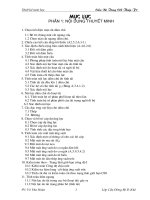
FIGURE 25.1 Typical FRP reinforcing bars for concrete members.
25.2 Design of FRP-Reinforced Concrete Members
25.2.1 Introduction
Fiber-reinforced polymer (FRP) reinforcing bars and grids have been commercially produced for reinforcing concrete structures for over 30 years (ACI Committee 440, 1996; Bank, 2006; Nanni, 1993). FRP
reinforcing bars have been developed for prestressed and non-prestressed (conventional) concrete reinforcement. This section considers only non-prestressed reinforcement for concrete structures and follows
the procedures of ACI 440.1R-06, Guide for the Design and Construction of Structural Concrete Reinforced
with FRP Bars (ACI Committee 440, 2006). Note that ACI 440.1R-06 does not cover reinforcing with
prefabricated FRP grids and mats. Recommendations for the design of prestressed FRP-reinforced concrete can be found in ACI 440.4R-04, Prestressing Concrete with FRP Tendons (ACI Committee 440,
2004b). Current FRP reinforcing bars (referred to as FRP rebars in what follows) are commercially
produced using thermosetting polymer resins (commonly, polyester and vinylester) and glass, carbon,
or aramid reinforcing fibers. The most common bars produced today are glass-fiber-reinforced vinylester
bars. These are recommended for use in reinforcing applications for load-bearing concrete structures.
The bars are primarily longitudinally reinforced with volume fractions of fibers in the range of 50 to
60%. FRP reinforcing bars are usually produced by a process similar to pultrusion (Starr, 2000) and have
a surface deformation or texture to develop the bond to concrete. More information on the historical
development, constituent materials, and manufacturing processes of FRP rebars can be found in Bank
(2006). A photograph of some typical FRP reinforcing bars is provided in Figure 25.1. In addition to the
ACI design guidelines, a number of other design guides have been published for FRP-reinforced concrete.
These include Japanese (BRI, 1995: JSCE, 1997) and Canadian (ISIS, 2001; CSA, 2002) guides.
25.2.2 Properties of FRP Reinforcing Bars
Glass-fiber-reinforced vinylester bars are available from a number of manufacturers in the United States,
Europe, and Asia. Bars are typically produced in sizes ranging from 3/8 in. in diameter to 1-1/4 in. in
diameter (i.e., #3 to #10 bars.) FRP bars have a non-smooth surface, which is required for bond to the
concrete (see Figure 25.1) and is typically produced by a sand-coated external layer, molded deformations, machined ribs, or a spiral wind. The properties of FRP rebars are intended to be measured and
reported by FRP rebar manufacturers in accordance with ACI 440.3R-04, Guide Test Methods for FiberReinforced Polymers (FRP) for Reinforcing or Strengthening Concrete Structures (ACI Committee 440,
2004a). A standard product specification for FRP rebars has recently been approved for publication by
the Canadian Standards Organization (ISIS, 2006). The ACI is currently preparing a standard specification
25-3
Design of FRP Reinforced and Strengthened Concrete
TABLE 25.1 Properties of Typical Commercially Produced FRP Reinforcing Bars
Glass-Reinforced
Vinylester Bara,b,c
(0.5-in. Diameter)
Glass-Reinforced
Vinylester Bara
(1-in. Diameter)
Carbon-Reinforced
Vinylester Bara
(0.375-in. Diameter)
Carbon-Reinforced
Epoxy Bar
(0.5-in. Diameter)
Fiber volume (estimated)
Fiber architecture
50–60
Unidirectional
50–60
Unidirectional
50–60
Unidirectional
50–60
Unidirectional
Strength (× 103 psi)
Tensile, longitudinal
Compressive, longitudinal
Bond strength
Shear, out-of-plane
90–100
NR
1.7
22–27
80
NR
1.7
22
300
NR
1.3
NR
327
NR
NR
NR
5.9–6.1
NR
3.7–4.9
12.2–18.7
60
NR
0.072
5.9
NR
3.7
18.7
60
NR
0.072
18
NR
–4.0–0
41–58
48–55
NR
NR
21.3
NR
0.38
NR
NR
NR
0.058
Stiffness (× 106 psi)
Tensile, longitudinal
Compressive, longitudinal
CTE, longitudinal (10–6/˚F)
CTE, transverse (10–6/˚F)
Barcol hardness
24-hour water absorption (% max.)
Density (lb/in.3)
a
Data for Aslan® (Hughes Brothers, Seward, Nebraska).
Data for V-Rod™ (Pultrall, Quebec, Canada).
c Data for Leadline® (Mitsubishi, Tokyo, Japan).
Note: CTE, coefficient of thermal expansion; NR, not reported by the manufacturer.
b
for FRP bars. For design, the key mechanical properties of interest are the longitudinal tensile strength
and longitudinal tensile modulus of the bar. Most FRP bars are brittle and exhibit strongly linear and
elastic axial stress–strain or axial load-deformation characteristics up to their failure loads. They do not
yield and have no plastic deformation capacity as do steel rebars. It is also important to note that, unlike
steel rebars, the longitudinal strength (but not the longitudinal modulus) of FRP rebars decreases with
the diameter of the bar. This is attributed to the relatively low in-plane shear modulus of FRP rebars
(leading to shear lag effects), the additives used to produce larger diameter bars, and a statistical size
effect in brittle glass fibers. Designers should always consult the manufacturer’s published properties
for use in design. Typical properties for glass-fiber FRP rebars and carbon-fiber FRP bars are provided
in Table 25.1. It should be noted that the carbon-fiber bars are typically used as prestressing tendons
or near-surface-mounted (NSM) strengthening rods and not as conventional reinforcing bars due to
cost considerations.
Fiber-reinforced polymer rebars are considered to be transversely isotropic from a mechanics perspective (Bank, 1993). Theoretical equations are available to predict the mechanical and physical properties
of the FRP rebars from the properties of the fiber and resin constituents; however, for design purposes,
measured properties of the as-produced bars must be used. At this time, theoretical methods are not yet
available to predict the bond properties and the long-term durability characteristics of FRP rebars. Test
methods for determining and reporting the alkali resistance, creep, and fatigue characteristics of FRP
rebars are provided in ACI 440.3R-04 (ACI Committee 440, 2004a). FRP rebars containing glass fibers
can fail catastrophically under sustained loads at stresses lower than their tensile strengths, a phenomenon
known as creep rupture or static fatigue. Design guides therefore limit the amount of sustained load on
concrete structures reinforced with FRP rebars.
Fiber-reinforced polymer rebars should only be used at service temperatures below the glass transition
temperature (Tg) of the polymer resin system used in the bar. For typical vinylester polymers, this is
around 200°F. The bond properties have been shown to be highly dependent on the glass transition
temperature of the polymer. In addition, it is important to note that the coefficients of thermal expansion
of FRP rebars are not the same in the transverse (radial) direction as in the longitudinal direction. The
coefficient of thermal expansion may be close to an order of magnitude higher in the transverse direction
25-4
Concrete Construction Engineering Handbook
of the bar due to its anisotropic properties (see typical properties in Table 25.1). This may cause longitudinal splitting in the concrete due to temperature and shrinkage effects if sufficient cover is not provided.
Fiber-reinforced polymer reinforcing bars made of thermosetting polymers cannot be bent in the field
and must be produced by the FRP rebar manufacturer with bends for anchorages or for stirrups. The
strength of the FRP rebar at the bend is substantially reduced and must be considered in the design.
According to ACI 440.1R-06, FRP rebars should not be used for carrying compressive stress in concrete
members (i.e., compression reinforcement in beams or columns) as this time, as insufficient research has
been conducted on this topic. Where FRP bars are used in the compression zone they should be suitably
confined to prevent local instability.
25.2.3 Design Basis for FRP-Reinforced Concrete
The load and resistance factor design (LRFD) basis is stipulated by ACI 440.1R-06, which provides the
resistance factors (φ, or phi factors) for use with FRP rebars that are calibrated for the load factors required
for use in design with conventionally reinforced concrete structures by ACI 318-05 (e.g., 1.2 for dead
load and 1.6 for live load) (ACI Committee 318, 2005). For the design of flexural members reinforced
with FRP rebars, ACI 440.1R-06 provides the following resistance factors:
Flexural capacity (tensile reinforcement only):
φ = 0.55 for an under-reinforced beam section (ρf < ρfb).
φ = 0.65 for a substantially over-reinforced beam section (ρf > 1.4ρfb).
φ = 0.3 + 0.25ρf/ρfb for a lightly over-reinforced beam section (ρfb < ρ < 1.4ρfb).
Shear capacity (FRP shear reinforcement in the form of stirrups):
φ = 0.75 per ACI 318-05.
where ρf is the FRP reinforcement ratio and ρfb is the balanced FRP reinforcement ratio. The FRP
reinforcement ratio for an FRP-reinforced rectangular beam section (where the subscript f is used to
indicate FRP reinforcement to distinguish it from conventional reinforcement) is given as:
ρf =
Af
bd
(25.1)
and the balanced FRP reinforcement ratio is given as:
ρ fb = 0.85β1
f c′ E f εcu
f fu E f εcu + f fu
(25.2)
where Af is the area of FRP reinforcement, b is the beam width, d is the effective depth, β1 is a factor that
depends on concrete strength (e.g., 0.85 for 4000-psi concrete), fc′ is the cylinder compressive strength
of the concrete, Ef is the longitudinal modulus of the FRP rebar, εcu is the nominal ultimate compressive
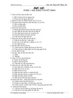
strain in the concrete (taken as 0.003), and ffu is the longitudinal design strength of the FRP rebar. Figure
25.2 shows the distribution of strains, stresses, and forces at the service condition and at the ultimate
condition for an FRP reinforced section.
The design strength (ffu) and design failure strain (εfu) are obtained from the manufacturer-reported
guaranteed strength and guaranteed failure strain by multiplying them by an environmental reduction
factor (CE), which depends on the fiber type in the bar and the type of intended service of the structure.
For example, for glass FRP rebars, CE is 0.7 for exterior concrete and 0.8 for interior concrete. The
guaranteed strength and guaranteed strain to failure of FRP rebars are defined as the mean minus 3
standard deviations of a minimum of 25 test samples (ACI Committee 440, 2006).
In addition to the strength criteria described above, the design basis for FRP-reinforced concrete members also includes stipulations on the behavior and appearance of the FRP-reinforced member under service
25-5
Design of FRP Reinforced and Strengthened Concrete
εc or εcu
–
c or cb
0.85f cʹ
fc
fc
2c/3
f cʹ
C = 0.5f ccb
β1cb
C = 0.85f cʹβ1cbb
d
Af
+
εc or εcu
b
Section
ff
T = Afff
Stresses and
forces at
service loads
Strains
ffu
T = Afffu
Stresses and
forces at
ultimate loads
FIGURE 25.2 Strains, stresses, and forces in the FRP-reinforced section at service and ultimate loads.
loads. Maximum flexural crack widths are limited to 0.20 and 0.28 mils for exterior and interiors exposure,
and the stress in the main FRP reinforcing bars is limited to 0.2ffu, 0.3ffu, and 0.55ffu for glass, aramid, and
carbon bars, respectively, to prevent failure under sustained loads due to creep rupture or due to fatigue.
Because FRP rebars typically have a lower modulus than steel rebars, the serviceability criteria (typically,
deflections and crack widths) can often control the design of FRP-reinforced concrete sections.
25.2.4 Design of Flexural Members with FRP Reinforcing Bars
25.2.4.1 Flexural Capacity with FRP Main Tension Bars
The nominal moment (or flexural) capacity of an FRP-reinforced concrete member (such as a beam or
a slab) is determined in a manner similar to that of a steel-reinforced section. However, because FRP
rebars do not yield, the ultimate strength of the bar replaces the yield strength of the steel rebar in the
traditional concrete beam design formula based on strain compatibility (assuming plane sections remain
plane and bars are perfectly bonded to the concrete) and equilibrium of forces. Both under-reinforced
section design and over-reinforced section design are permitted; however, due to serviceability limits
(primarily long-term deflections and crack widths), most glass FRP-reinforced flexural members will be
over-reinforced.
When ρf > ρfb , the over-reinforced section will fail due to concrete crushing, and the nominal moment
capacity is given in a manner similar to that for a section reinforced with steel rebars (where the rebar
has not reached its yield stress). The stress in the rebar therefore must be calculated to determine the
capacity of the section. The nominal moment capacity is given as:
a
Mn = Af f f d −
2
(25.3)
where:
a=
ff =
(E ε )
f
cu
4
2
+
Af f f
0.85 f c′b
0.85β1 f c′
E f εcu − 0.5E f εcu
ρf
(25.4)
(25.5)
where ff is the stress in the FRP rebar at concrete compressive failure, and a is the depth of the equivalent
rectangular (Whitney) stress block in the concrete.
25-6
Concrete Construction Engineering Handbook
When ρf < ρfb , the under-reinforced section will fail due to rupture of the FRP rebars in tension.
Because the FRP reinforcement will not yield prior to its failure, the moment capacity of the section
cannot be calculated assuming the concrete crushes when the bar ruptures (as in the case of a steel underreinforced section). For this reason, the section capacity should be calculated using appropriate nonlinear stress–strain relations of the concrete; however, this requires an iterative solution procedure, which
is not suited to design calculations. To overcome this situation, ACI 440.1R-06 recommends computing
the approximate (and conservative) nominal flexural capacity as:
βc
M n = A f f fu d − 1 b
2
(25.6)
where cb is the depth of the neutral axis at the balanced reinforcement ratio, given as:
εcu
cb =
d
εcu + ε fu
(25.7)
A minimum amount of flexural reinforcement should be provided when the FRP-reinforced beam is
designed to fail by FRP bar rupture to prevent failure at concrete cracking. The amount is given as:
A f ,min =
4.9 f c′
330
bd ≥
bd
f fu
f fu
(25.8)
25.2.4.2 Shear Capacity with FRP Main Tension Bars and FRP Shear Reinforcement
The nominal shear capacity of an FRP-reinforced concrete member loaded in flexure is influenced by
the mechanical properties of the FRP main tension reinforcing bars and by FRP shear reinforcement,
which is typically supplied in the form premanufactured stirrups. The lower modulus of the FRP main
bars (assuming glass fibers) leads to a shallower compression zone and larger deflections at flexural failure
of FRP-reinforced flexural members than would be obtained in the same section reinforced with steel
bars. In addition, the strain in the FRP stirrups is limited to prevent large shear cracks from developing
in the FRP-reinforced concrete member. Added to this, the strength of the FRP bar is reduced when it
is bent to form a stirrup due to the linear elastic material properties and the manufacturing process used
to manufacture bent FRP bars.
The nominal shear capacity (Vn) of an FRP-reinforced concrete beam is:
Vn = Vc + V f
(25.9)
where Vc is the nominal shear capacity of the concrete with FRP rebars used as main tension reinforcement
and is given as:
Vc = 5 f c′ bwc
(25.10)
where bw is the width of the beam web, and c is the depth of the neutral axis in the cracked elastic section
as defined for the serviceability calculations and is given as:
c = kd
k=
(ρ η )
f
f
2
+ 2ρ f η f − ρ f η f
ηf =
Ef
Ec
(25.11)
(25.12)
(25.13)
25-7
Design of FRP Reinforced and Strengthened Concrete
where ηf is the modular ratio, k is the depth ratio, and Vf is the nominal shear capacity provided by the
FRP stirrups. For vertical FRP shear stirrups, it is given as:
Vf =
A fv f fv d
s
(25.14)
where Afv is the total area of the stirrups that cross the shear crack, and ffv is the strength of the FRP
stirrup, which is limited by the smaller of:
f fv = 0.004E f
(25.15)
and the strength of the FRP rebar at its bend:
r
f fb = 0.05 b + 0.3 f fu
db
(25.16)
where ffb is the strength of the FRP rebar at its bend, rb is the inside radius of the bend, and db is the
diameter of the FRP rebar. Standard bend radii are reported by manufacturers and range from 4.25 to
6 in. for typical FRP rebars. The ratio of rb/db may not be less than 3.
25.2.4.3 Design for Serviceability
For serviceability design of concrete members with FRP bars three criteria, all calculated with respect to
the service loads on the member (with no load factors applied), must be checked against code-stipulated
limits provided in ACI 440.1R-06: (1) maximum crack widths due to all loads, (2) maximum short-term
and long-term deflections due to all loads accounting for long-term creep effects, and (3) maximum
stresses in the FRP bars due exclusively to sustained loads and fatigue. The width of a flexural crack in
an FRP-reinforced member is calculated from:
w=2
ff
s
βkb dc2 +
2
Ef
2
(25.17)
where w is the crack width (in inches), ff is the service load stress in the FRP reinforcement (in ksi), Ef
is the modulus of the FRP rebars (in ksi), β is the ratio of the distance between the neutral axis and the
bottom of the section (i.e., the tension surface) and the distance between the neutral axis and the centroid
of reinforcement, dc is the thickness of the concrete cover from the tension face to center of the closest
bar (in inches), s is the center-to-center bar spacing of the main FRP bars (in inches), and kb is a bondrelated coefficient. kb is taken as 1.4 for commercially produced FRP rebars. β is determined from:
β=
h − kd
d (1 − k )
(25.18)
where h is the section depth and d is the effective section depth. The stress in the FRP bar at service loads
can be calculated from:
f f ,s =
where ms is the service load moment.
ms η f d (1 − k )
I cr
(25.19)
25-8
Concrete Construction Engineering Handbook
To calculate maximum short-term and long-term deflections under service loads, a modified form of
the Branson equation is used:
3
M 3
M
I e = cr βd I g + 1 − cr I cr ≤ I g
Ma
M a
(25.20)
where Ie is the effective second moment of area of the cracked section, Ig is the second moment of the
gross section, Mcr is the moment at cracking, Ma is the applied service load moment, and βd is a reduction
coefficient for FRP reinforced beams that is given as:
1 ρf
βd =
≤ 1.0
5 ρ fb
(25.21)
As in conventional steel-reinforced concrete, the cracked (transformed to concrete) second moment of
the section is given as:
I cr =
2
bd 3 3
k + η f A f d 2 (1 − k )
3
(25.22)
The long-term deflections, including the effects of creep and shrinkage of the concrete under the sustained
long-term service loads (i.e., the dead load and the sustained live load), can be calculated as:
∆ (cp +sh ) = 0.6ξ ( ∆i )sus
(25.23)
where (∆i)sus is the short-term (or instantaneous) deflection due to the sustained loads only and is
calculated using the modified Branson formula; ξ = 2.0 for sustained loads with a duration of 5 years
or more as per ACI 318-05 (ACI Committee 318, 2005).
All FRP-reinforced concrete beams must be checked for possible failure due to creep rupture or fatigue
under service loads. Creep rupture is checked with respect to all sustained service loads, whereas fatigue
is checked with respect to all sustained loads plus the maximum moment induced in a fatigue loading cycle:
f f , creep rupture =
msus η f d (1 − k )
I cr
(25.24)
where msus is the moment due to the sustained service loads.
25.2.4.4 Detailing of FRP Reinforcements
The development length of an FRP rebar is different from the development length of a conventional steel
rebar. In addition, a beam reinforced with FRP bars can potentially fail due to splitting bond failure
between the FRP bar and the concrete due to the high tensile stress that can be developed in FRP bars.
The required development length (ld) for a straight FRP bar is given as:
α
d
=
f fr
f c′
− 340
C
13.6 +
db
(d )
b
(25.25)
where ffr is the stress in the FRP bar at failure which is the lesser of (1) the design strength of the bar for
under-reinforced beams (ffu), (2) the actual stress in the bar for over-reinforced sections (ff ), or (3) the
effective bond critical design stress in the bar for both over and under-reinforced sections (ffe), which is
given as:
Design of FRP Reinforced and Strengthened Concrete
f fe =
f c′
C e
13.6 e +
+ 340 ≤ f fu
α
db db db
25-9
(25.26)
where C is the lesser of (1) the distance from the center of the bar to the nearest outer concrete surface
in the tension zone, or (2) half the on-center spacing of the bars (side-by-side); α is the bar location
factor, which is taken as 1.0 for bars that are in the bottom 12 in. of the formwork when the concrete is
cast and as 1.5 when the bars are more than 12 in. above the bottom of formwork when the beam is cast
(known as top-bars). ACI 440.1R-06 further recommends that the term C/db not be taken as larger than
3.5 and that the minimum embedment length (le) be at least 20 bar diameters, or 20db.
For hooked bars, the development length of the portion extending beyond the bend (the tail length)
is given as a function of the FRP rebar design strength. For FRP rebars with design strengths in the range
of 75 to 150 ksi (typical of glass FRP rebars), the length of the hook (lbfh) is given as:
lbhf =
f fu db
37.5 f c′
(25.27)
It should not be less than 12db or 9 in. Tension lap splices for FRP rebars are based on recommendations
for steel rebars and limited test data. For Class A and Class B lap splices, the recommended develop
lengths are 1.3ldf and 1.6ldf, respectively. FRP stirrups can be spaced at a maximum of d/2 (or 24 in.) and
should have a minimum rb/db ratio of 3. The tail length of 90° hooks in the stirrups must be at least 12db.
25.3 Design of FRP-Strengthened Concrete Members
25.3.1 Introduction
Fiber-reinforced polymer reinforcing systems for strengthening structurally deficient concrete structural
members and for repairing damaged or deteriorated concrete structures have been used since the mid1980s (Bank, 2006). This section provides guidance for the design of FRP strengthening systems according
to the procedures of ACI 440.2R-02, Guide to the Design and Construction of Externally Bonded FRP
Systems for Strengthening Concrete Structures (ACI Committee 440, 2002). This guide is used for the
design of most FRP strengthening systems currently designed in the United States. This guide is still
based on ACI 318-99 load factors (e.g., 1.4 for deal loads and 1.7 for live loads). It is currently under
revision and, in addition to other changes, the next edition will be compatible with ACI 318-05 load
factors (e.g., 1.2 for dead loads and 1.6 for live loads). The reader is advised to consult the new version
of this guide when it is released in 2008.
The first FRP-strengthened concrete structures were beams strengthened to increase their flexural
capacity using high-strength, lightweight, carbon-fiber-reinforced epoxy laminates that were bonded to
the undersides of the beams. The method is a modification of one where epoxy-bonded steel plates are
used to strengthen concrete beams which has been in use since the mid-1960s. The FRP systems were
shown to provide significant benefits in constructability and durability over the steel plates. Thereafter,
significant work was conducted on strengthening of concrete columns to enhance their axial capacity,
shear capacity, and ductility, primarily for seismic loadings. This method is a modification of one using
steel jackets to strengthen concrete columns. This was followed closely by work on shear strengthening
of beams. A review of the state of the art on the subject can be found Teng et al. (2001), Hollaway and
Head (2001), and Bank (2006). The method has also been used to strengthen masonry and timber
structures; however, applications of this type are not discussed in this chapter.
Current FRP strengthening systems for concrete fall into two popular types: precured and formed-inplace systems. The precured systems consist of factory manufactured laminates (known as strips or plates)
of carbon-or glass-reinforced thermosetting polymers (typically epoxy or vinylester) that are bonded to
the surface of the concrete using an epoxy adhesive. The manufactured precured laminates typically have
25-10
Concrete Construction Engineering Handbook
FIGURE 25.3 Typical FRP strengthening systems for concrete members.
a volume fraction of fibers in the range of 55 to 65% and are cured at high temperatures (>300°F) but are
bonded in the field at ambient temperatures. The formed-in-place systems consist of layers of unidirectional
sheets or woven or stitched fabrics of dry fibers (usually glass, carbon, or aramid) that are saturated in the
field with a thermosetting polymer (e.g., epoxy or vinylester) which simultaneously produces and bonds
the FRP material to the concrete. The process is often referred to as lay-up. The formed-in-place FRP
systems typically have a fiber volume fraction of between 20 and 40% and are cured at ambient temperatures in the field. Figure 25.3 shows a number of currently produced FRP strengthening systems.
A number of design guides and national standards are currently published that provide recommendations for the analysis, design, and construction of concrete structures strengthened with FRP materials
(Concrete Society, 2004; CSA, 2002; FIB, 2001; ICC Evaluation Service, 1997; JSCE, 2001). In addition,
manufacturers of FRP strengthening systems for concrete typically provide their own design and installation guides for their proprietary systems. Because the performance of the FRP strengthening system is
highly dependent on the adhesive or saturating polymer used, the preparation of the concrete surface
prior to application of the FRP strengthening system, and the field installation and construction procedures, manufacturers frequently certify approved contractors to ensure that their systems are designed
and installed correctly. Guidance to ensure that FRP strengthening systems are appropriately installed,
monitored, and inspected is provided in a number of guides (Concrete Society, 2003; ICC Evaluation
Service, 2001; TRB, 2004).
25.3.2 Properties of FRP Strengthening Systems
Carbon-fiber-reinforced epoxy laminates (or strips) are the most commonly used of the precured FRP
strengthening systems. Depending on the type of carbon fiber used in the strip, different longitudinal
strengths and stiffness are produced. Strips are typically thin (less than 0.100 in.) and are available in a
variety of widths (typically 2 to 4 in.). Because the strips are reinforced with unidirectional fibers, they
are highly orthotropic with very low properties in the transverse and through the thickness directions.
Manufacturers typically only report properties in the longitudinal directions and report very little data on
physical properties. The strips are bonded to the concrete with an adhesive that is supplied by the strip
manufacturer. Typical properties of strips are shown in Table 25.2. It is important to note that the properties
shown for the strips are properties of the FRP composite and not the properties of the fibers alone.
In the formed-in-place FRP strengthening systems, a greater array of products is available depending
on fiber type and sheet or fabric architecture. In this group of products, a unidirectional, highly orthotropic carbon-fiber tow sheet is produced by a number of manufacturers and is often used in strengthening
25-11
Design of FRP Reinforced and Strengthened Concrete
TABLE 25.2 Properties of Typical Commercially Produced FRP Strengthening Strips
Standard-Modulus
Carbon-Reinforced
Epoxy Stripa,b,c
High-Modulus
Carbon-Reinforced
Epoxy Stripa
Glass-Reinforced
Epoxy Stripb
Carbon-Reinforced
Vinylester Stripd
65–70
Unidirectional
0.047–0.075
2–4
65–70
Unidirectional
0.047
2–4
65–70
Unidirectional
0.055–0.075
2–4
60
Unidirectional
0.079
0.63
Strength (× 103 psi)
Tensile, longitudinal
390–406
188
130
300
Rupture strain (%)
Tensile, longitudinal
1.8
NR
2.2
1.7
22.5–23.9
NR
NR
NR
43.5
NR
NR
NR
6.0
NR
NR
NR
19.0
–4.0–0.0
41–58
48–55
Fiber volume (estimated)
Fiber architecture
Nominal thickness (in.)
Width (in.)
Stiffness (× 106 psi)
Tensile, longitudinal
CTE, longitudinal (10–6/˚F)
CTE, transverse (10–6/°F)
Barcol hardness
a
Data for CarboDur® (Sika Group; Zurich, Switzerland).
Data for Tyfo® (Fyfe; San Diego, California).
c Data for MBrace® (BASF Construction Chemicals; Seven Hills, New South Wales, Australia).
d Data for Aslan® (Hughes Brothers; Seward, Nebraska).
Note: CTE, coefficient of thermal expansion; NR, not reported by the manufacturer. All strips must be bonded with
manufacturer-supplied compatible adhesives.
b
applications. The individual carbon tows in the sheet are held together by a polymeric binder (or a light
stitching). The sheet is often supplied on a wax paper backing. Sheets are typically 10 to 40 inches wide
and can be applied in multiple layers with different orientations. The common fabric materials in the
formed-in-place group are woven or stitched fiber fabrics having an areal density of 12 to 32 oz/yd2.
Carbon-fiber fabrics and hybrid fabrics (with more than one fiber type) are also available. Fabrics are
typically much thicker than tow sheets. They are also used in multiple layers. Because of the wide variety
of products available and their different thicknesses, it is not easy to compare their properties directly.
In addition, the fibers must be used with a compatible resin system applied at a controlled volume fraction
to achieve a FRP composite with desirable properties. In the case of sheet and fabric materials, manufacturers typically report the mechanical properties of the dry fibers and the thickness (or area) of the
fibers. It is important to note that when reported in this fashion the properties are not the properties of
the FRP composite but of the fibers alone. Properties of some commonly available fiber sheet and fabric
materials are listed in Table 25.3.
The performance of the FRP strengthening system is highly influenced by the properties of the adhesive
layer in the case of the precured systems and by the properties of the saturating polymeric resin in the
case of formed-in-place systems. The interface between the FRP composite and the concrete substrate
transfers the loads from the concrete to the FRP composite. In the case of flexural and shear (or axial
tensile) strengthening, this load transfer is primarily in shear, and the strength and stiffness of the interface
layer between the FRP composite and the concrete are critical. Such applications are termed bond critical.
In the case of axial compressive strengthening or lateral displacement ductility enhancement of columns,
the role of the strengthening system is to confine the lateral expansion of the cracked concrete. In this
case, the interface bond is not as critical as long as the FRP system is in close contact with the concrete
and is wrapped around the concrete continuously so as to provide a confining pressure with appropriate
hoop stiffness and strength. Such applications are termed contact critical.
The FRP strengthening systems described above all depend on curing of the polymer adhesives or the
saturating resins at ambient temperature in the field; therefore, the glass transition temperature (Tg) of these
systems is typically quite low (120 to 180°F). The stiffness of the FRP strengthening system is decreased
25-12
Concrete Construction Engineering Handbook
TABLE 25.3 Properties of Typical Commercially Produced FRP Sheet-Strengthening Materials
Standard-Modulus
Carbon Fiber
Tow Sheeta,b,c
High-Modulus
Carbon Fiber
Tow Sheeta,b
Glass Fiber
Roving Sheeta,b
0.0065–0.013
24
Unidirectional
0.0065
24
Unidirectional
0.014
24
Unidirectional
Strength (× 103 psi)
Fiber tensile, longitudinal
550
510
220–470
Rupture strain (%)
Fiber tensile, longitudinal
1.67–1.7
0.94
2.1–4.5
33.0–33.4
54.0
10.5
Thickness (in.)
Typical width (in.)
Fiber architecture
6
Stiffness (× 10 psi)
Fiber tensile, longitudinal
a
b
c
Data for MBrace® (BASF Construction Chemicals, Seven Hills, New South Wales, Australia).
Data for Tyfo® (Fyfe, San Diego, California).
Replark™ (Mitsubishi, Tokyo, Japan).
when the operating temperature approaches (and exceeds) the glass transition temperature. Designers
should always be aware of the glass transition temperature of the FRP composite or adhesive they are using
in a design. In the event of a fire (at temperatures higher than the Tg in the range of 750°F), the FRP material
will decompose (pyrolize), and its strength and stiffness may be severely compromised in a short time.
25.3.3 Design Basis for FRP Strengthening Systems for Concrete Members
The load and resistance factor design (LRFD) basis is stipulated by ACI 440.2R-02 (ACI Committee 440,
2002). Currently, resistance factors are not probabilistically based, and the load factors stipulated for use
with this guide are those recommended by ACI 318-99 (e.g., 1.4 for dead loads and 1.7 for live loads)
(ACI Committee 318, 1999). (The revised version of the guide, due out in 2008, will have probabilistically
based resistance factors and will be compatible with ACI 318-05.) For the design of concrete members
with FRP strengthening systems the ACI recommends the following resistance factors (φ) and FRP
material reduction factors, (ψf ):
For flexural capacity:
φ = 0.9 for ductile failure of the member following steel yielding (εs > 0.005).
φ = 0.7 for a brittle failure when the member fails prior to steel yielding (εs < εsy).
φ = 0.7 to 0.9 for an intermediate region (εsy < εs < 0.005).
ψf = 0.85 for FRP bond-critical strengths (applied in addition to φ factors).
For shear capacity:
φ = 0.85, per ACI 318-99.
ψf = 0.85 for FRP bond-critical strengths (applied in addition to φ factor).
ψf = 0.95 for FRP contact-critical strengths (applied in addition to φ factor).
For axial capacity:
φ = 0.75, per ACI 318-99, for spiral steel column reinforcement.
φ = 0.70, per ACI 318-99, for tied steel column reinforcement.
ψf = 0.95 for FRP contact-critical strengths (in addition to φ factors).
Guaranteed strengths and strains to failure of FRP composite materials for strengthening are defined
as the mean minus 3 standard deviations of a minimum of 20 test samples tested in accordance with
ACI 440.3R-04 (ACI Committee 440, 2004a). The design strength (ffu) and design failure strain (εfu) are
Design of FRP Reinforced and Strengthened Concrete
25-13
obtained from the manufacturer-reported guaranteed strength and failure strain by multiplying them by
an environmental reduction factor (CE), which depends on the fiber type in the FRP strengthening system
and the type of intended service of the structure. For example, for weather-exposed concrete with a glassreinforced epoxy FRP strengthening system, CE is 0.65 (ACI Committee 440, 2002). Note that the
environmental reduction factors for FRP strengthening systems are not the same as the environmental
reduction factors for FRP reinforcing bars (even though the same symbol is used for both.)
Even though flexural strength increases of over 100% of the original strength of a concrete member
can be obtained using FRP strengthening systems, the ACI limits the amount of strengthening to prevent
catastrophic failure of the concrete member in the event of loss of, or damage to, the strengthening system
(due to vandalism or environmental degradation). The ACI recommends that the strengthened member
still have sufficient original factored capacity (i.e., discounting the additional strengthening system) to
resist a substantial portion of the increased (new) factored load for which the strengthened member is
designed. This limit is given as:
1.2D + 0.85L
(25.28)
where D represents the new dead load effect, and L the new live load effect, such as bending moment,
shear force, or axial load or their products (stress and strain). To account for environments where the
FRP may be exposed to fire, additional restrictions are placed on the factored capacity of the FRPstrengthened structure:
1.0D + 1.0L
(25.29)
Fire protection systems are available to protect FRP strengthening systems to increase their fire ratings
to building code required ratings (such as 1- or 2-hour ratings). When a concrete member is strengthened
to increase its capacity in a selected mode (e.g., flexure), the member must be checked to ensure that the
capacities in other failure modes (e.g., shear) are not exceeded. If this is the case, the strengthening should
be decreased or the secondary capacity must be enhanced with its own strengthening system.
For serviceability design, the ACI 440.2R-02 guide limits the stress in the steel at service loads to 80%
of the steel yield stress and limits the sustained plus cyclic stress in the FRP strengthening system to
account for creep rupture and fatigue, depending on the fiber system. For carbon FRP strengthening
systems, this limit is 55% of the ultimate strength. At this time, ACI 440.2R-02 does not provide special
recommendations for the determination of deflections or crack widths for FRP-strengthened members.
Flexural deflections in the service range can be estimated by use of an effective second moment of area
(Ie) analysis, where the tensile contribution of the FRP is added to the contribution of the steel reinforcing.
For deflections in flexural members where stresses are in the service load range, the contribution of the
FRP strengthening system is typically small. In the inelastic range (after the primary reinforcing steel has
yielded), the contribution of the FRP strengthening to the post-yield stiffness can be quite considerable
and should be accounted for in inelastic analysis (Bank, 2006).
It is extremely important to note that the method of determining the tensile force resultant in an FRP
strengthening system depends on the type of system used. In the bonded, precured strip, the ultimate
force is obtained from the strength of the FRP composite (see Table 25.2) and the gross cross-sectional
area of the strip. In formed-in-place systems, the ultimate force is obtained from the strength of the fibers
and the net area of the fibers (see Table 25.3). The designer must know if the reported strength (and
stiffness) of an FRP strengthening system is for the FRP composite (gross composite cross-section) or
for the fibers alone (net fiber cross-section). Both methods of calculation are permitted by ACI 440.2R-02.
25.3.4 Design of FRP Flexural Strengthening Systems
Flexural strengthening is achieved by attaching an FRP strengthening system (precured strip or formedin-place fabric) to the underside of a flexural member to increase the effective tensile force resultant in
the member and thereby increase the moment capacity of the member. This is analogous to adding steel
strengthening strips (or plates) to the underside of a member; however, two fundamental differences
25-14
Concrete Construction Engineering Handbook
exist. First, the FRP strengthening system behaves in a linear elastic fashion and does not yield, and,
second, the FRP strengthening system is more susceptible to detachment (debonding or delamination)
failures than steel plate systems that are anchored with steel bolts in addition to the epoxy bonding.
Because the steel plates themselves will yield at a similar strain to the internal steel reinforcing, the stress
level in the steel strengthening system is limited. In the case of FRP strengthening with FRP systems
having ultimate tensile strengths exceeding 300 ksi (see Table 25.2 and Table 25.3), the stress level in the
FRP can be significantly higher than that in steel strengthening systems. In the event that the internal
steel reinforcing yields before the FRP strengthening system fails (the desired failure mode), the concrete
member will undergo large deflections and cracking. All of these factors lead to the greater likelihood
that the FRP strengthening system will debond from the concrete before it achieves its ultimate (longitudinal) tensile strength.
Strengthening of members in flexure can only be achieved if there is sufficient additional compressive
capacity in the concrete to allow for the increase in internal moment; therefore, flexural strengthening
is most suitable for concrete members that are lightly to moderately reinforced, having steel reinforcement
in the range of 20 to 40% of the balanced ratio. This is not uncommon in reinforced concrete members.
The existing tensile strain in the concrete at the location of the applied FRP strengthening system due
to sustained loads when the FRP strengthening system is applied should be accounted for in design
calculations if a shoring system is not used.
The key to flexural strengthening with FRP strengthening systems is to understand the failure modes
of the system. These include rupture of the FRP strengthening system, debonding of the FRP strengthening system, or compressive failure of the concrete. All of these modes can occur either before or after
the internal steel has yielded. The desired mode of failure is concrete compressive failure after the internal
steel has yielded with the FRP strengthening system still attached. The FRP strengthening system can
debond in a number of modes. The FRP system can delaminate from the concrete substrate (due to
failure in the concrete, the adhesive layer, or in the FRP laminate itself) either at the ends (due to high
peeling and shear stresses) or in the interior of the beam due to flexural and shear cracks in the beam
at large deflections. For a detailed discussion on debonding failure modes, see Teng et al (2001). Analytical
methods to predict the various debonding failure modes are still not fully developed, and ACI 440.2R-02
limits the tensile strain level in the FRP strengthening system to prevent debonding failure by use of an
empirically obtained, bond-dependent coefficient (κm) that is a function of the unit stiffness of the FRP
system and is defined as:
1
nE f t f
1−
≤ 0.90 for nE f t f ≤ 1, 000, 000 lb/in.
60ε fu 2, 000, 000
κm =
1 500, 000
60ε 1 − nE t ≤ 0.90 for nE f t f > 1, 000, 000 lb/in.
fu
f f
(25.30)
where εfu is the ultimate strain the FRP; n is the number of layers of FRP strips, sheets, or fabrics; Ef is
the longitudinal tensile modulus of the FRP composite in the case of strips or the longitudinal modulus
of the fibers in the strengthening direction in the case of sheets or fabrics; and tf is the thickness of an
individual strip in the case of FRP strips or the net thickness of the fibers in a single sheet or fabric in
the case of sheets or fabrics.
The strain level in the FRP strengthening system is limited by the strain in the concrete or the ultimate
strain in the FRP system and is given as:
h −c
ε fe = εcu
− εbi ≤ κ m ε fu
c
(25.31)
Design of FRP Reinforced and Strengthened Concrete
25-15
where εfe is the effective ultimate strain in the FRP at failure, εcu is the ultimate compressive strain in the
concrete (0.003), c is the depth of the neutral axis, h is the depth of the section, and εbi is the existing
tensile strain in the concrete substrate at the location of the FRP strengthening system when the FRP
system is applied.
The effective stress (ffe) in the FRP is the ultimate strength of the FRP that can be achieved at failure
and is linearly related to the ultimate strain as:
f fe = E f ε fe
(25.32)
The nominal moment capacity (Mn) of the strengthened section (with an existing layer of tensile steel
reinforcement) is given as:
βc
βc
M n = As f s d − 1 + ψ f A f f fe h − 1
2
2
(25.33)
with:
c=
As f s + A f f fe
γf c′β1b
(25.34)
and:
d −c
f s = E s ε s = E s ε fe + εbi
≤ fy
h − c
(
)
(25.35)
where As is the area of the tensile steel, fs is the stress in the steel at failure, d is the depth of the steel
reinforcing, β1 is the depth ratio of the equivalent Whitney stress block, Af is the area of the FRP strip
or the fibers only in a formed-in-place system, γ is the concrete stress resultant factor (0.85 when concrete
compressive failure governs), b is the width of the section, and fy is the yield stress in the reinforcing steel.
The solution to the above equations is typically found by a trial-and-error method by assuming a
number of layers of a specific strengthening system and calculating the resulting nominal moment.
Alternatively, a failure mode can be assumed a priori and the stresses in the materials checked using
closed-form equations, as described in Bank (2006). According to ACI 440.2R-02, the four currently
admissible failure modes are FRP debonding either before or after the internal steel yields or concrete
compressive crushing either before or after the internal steel yields. The stress distribution in the concrete
at failure of the strengthened member will depend on the failure mode of the strengthened member. If
the FRP debonds when the concrete strain is still low (less than 0.002), the failure is controlled by the
FRP, and a nonlinear stress distribution in the concrete should be used in determining the compressive
force in the section (Bank, 2006). This is not conducive to design calculations, however, and it is typically
assumed that the concrete stress can be represented by the Whitney stress block at failure even in this
case. Figure 25.4 shows the strains, stresses, and forces in an FRP-strengthened section at the ultimate
state according to this assumption. This assumption is felt to be reasonable because in an appropriately
designed strengthening system the steel will yield before the FRP debonds or ruptures and the strain in
the concrete will be larger than 0.002.
As with a conventional reinforced concrete section, a balanced reinforcement ratio can be defined that
includes the effect of the internal steel reinforcing and the externally applied FRP system (Bank, 2006).
The balanced ratio can be defined for failure of the section either prior to the internal steel yielding or
after the internal steel has yielded, although as mentioned previously the latter is preferable. The balanced
reinforcement ratio can be a useful tool in design but is not as important a parameter as in the design
of conventional reinforced concrete design (either steel or FRP reinforcement), because a strengthening
design depends on the properties of an existing section and it may not be always possible to achieve a
balanced condition in the strengthened section. The stresses in the steel and the FRP strengthening system
25-16
Concrete Construction Engineering Handbook
γ f cʹ
fc
εc
–
β1 c
c
h
C = γf ʹc β1cb
d
+
εs
As
Af
|
|
εbi εfe
|
ffe
b
Section
Tf = Asfs
fs
Tf = Afffe
Stresses and
forces at
ultimate loads
Strains
FIGURE 25.4 Strains, stresses, and forces in an FRP-strengthened section at ultimate loads.
at service loads should be determined using an elastic cracked section and checked against appropriate
stress limits for sustained loads on FRP strengthened structures according to ACI 440.2R-02. Mechanical
anchorages or FRP wraps can be used to enhance the attachment of the FRP strengthening system to the
concrete beam, especially at the ends of the FRP strengthening system. Design guidance is not provided
by the ACI 440.2R-02 for this, although the use of such a system is recommended by many manufacturers
to prevent debonding failures.
25.3.5 Design of FRP Shear Strengthening Systems
Fiber-reinforced polymer strengthening systems can be used to increase the shear capacity of concrete
beams and columns. FRP strengthening systems are applied to the webs of beams (or columns) and
function in an analogous fashion to internal steel shear reinforcement. Because FRP shear strengthening
systems are applied to concrete members that are often constructed monolithically with other continuous
members (such as floors and walls) it is not always possible wrap the FRP strengthening system completely
around the member (which is the desirable condition.) The FRP strengthening system must therefore
be terminated at the top of the web (a three-sided U-wrap) or terminated at both the top and the bottom
on the web (a two-sided wrap). The non-fully wrapped systems are susceptible to debonding failures
(similar to flexural strengthening), and their strains are limited by a shear bond-reduction coefficient
(κv), which is a function of the concrete strength, the wrapping type used, and the stiffness of the FRP
strengthening system. It is given by ACI 440.2R-02 (in U.S. units) as:
κv =
k1k 2 Le
≤ 0.75
468ε fu
(25.36)
where Le is the active bond length over which the shear stress is transferred between the FRP and the
concrete. It has been shown that it is this finite length that limits the maximum force that can be
transferred between the two materials regardless of the bonded length of the FRP strip. It is given as:
Le =
2500
(nt E )
0.58
f
(25.37)
f
The coefficients k1 and k2 are given as:
f′
k1 = c
4000
23
(25.38)
Design of FRP Reinforced and Strengthened Concrete
25-17
For three-sided shear strengthening systems:
k2 =
d f − Le
df
(25.39)
k2 =
d f − 2Le
df
(25.40)
For two-sided shear strengthening systems:
where df is the effective depth of the FRP shear strengthening system. For fully wrapped sections, it is
equal to the full depth (h) of the section, but for two- and three-sided wraps it is the vertical distance
from the top of the FRP system to the main tensile reinforcing bars in the beam and is less than h.
The nominal shear capacity of an FRP strengthened concrete member with existing steel shear reinforcing is determined by adding the contribution of the FRP strengthening system to the existing shear
capacity and is given as:
Vn = Vc + Vs + ψ f V f
(25.41)
where:
Vf =
A fv f fe ( sin α + cos α )d f
sf
(25.42)
A fv = 2nt f w f
(25.43)
f fe = E f ε fe
(25.44)
where Vc is the shear capacity of the concrete, Vs is the shear capacity of the existing steel shear reinforcement, and Vf is the shear capacity of the FRP strengthening system. The FRP material reduction
factor (ψf ) is taken as 0.95 for completely wrapped contact-critical sections and as 0.85 for bond-critical
two- or three-sided wrapped sections. Afv is the area of the FRP shear strengthening system, ffe is the
effective tensile stress in the FRP at ultimate, α is the inclination of the fiber in the FRP strengthening
system to the longitudinal axis of the member, sf is the center-to-center spacing of the FRP shear
strengthening strips, and wf is the width of the FRP shear strengthening strip. (For a continuous FRP
shear strengthening sheet or fabric, sf = wf ). Ef is the longitudinal modulus of the FRP strengthening
system, and εfe is the effective longitudinal strain in the FRP strengthening system.
The effective strain in the FRP shear strengthening system is limited to prevent debonding failures
and to maintain the integrity of the concrete aggregate interlock in the concrete member. For completely
wrapped FRP shear strengthening systems, the maximum effective strain in the FRP strengthening system
at failure is limited to:
ε fe = 0.004 ≤ 0.75ε fu
(25.45)
For two- or three-sided shear strengthening, the effective shear strain in the FRP strengthening system
at failure is limited to:
ε fe = κ v ε fu ≤ 0.004
(25.46)
Mechanical anchorages can be used to anchor two- or three-sided wraps in the compression zone of the
web; however, design guidance is not provided by ACI 440.2R-02.
When FRP shear strengthening is added to the conventional steel shear reinforcement, the shear
reinforcement limit for conventional concrete members must hold for both types of reinforcement:
25-18
Concrete Construction Engineering Handbook
Vs + V f ≤ 8 f c′bw d
(25.47)
When intermittent strips are used, a maximum spacing between the strips is mandated so every shear
crack will be covered by sufficient strip width. The following maximum spacing of intermittent strips is
required:
s max
=
f
df
+wf
4
(25.48)
25.3.6 Design of FRP Axial Strengthening Systems
Concrete compression members can be strengthened to increase their axial load carrying capacity, their
shear capacity, their steel rebar lap splice capacity, and their lateral load carrying deformation capacity
(which is related to the ductility of the member). FRP strengthening of columns is most effective when
applied to circular columns and must always consist of complete wrapping to obtain confinement of the
concrete. FRP strengthening systems for confinement of columns are classifieds as contact-critical applications. It is also important to note that FRP axial strengthening systems are regarded as passive systems;
that is, they are not effective (or active) until the concrete reaches its transverse cracking strain and begins
to dilate, thus placing hoop stress on the FRP wrap. This is in contrast to the FRP flexural and shear
strengthening systems that must be active at all load levels.
For a non-slender, non-prestressed, normal weight concrete column reinforced with steel spiral reinforcement, the nominal axial capacity is given as:
(
(
)
Pn = 0.85 0.85ψ f f cc′ Ag − Ast + f y Ast
)
(25.49)
and for steel tied reinforcement, the nominal axial capacity is given as:
(
(
)
Pn = 0.80 0.85ψ f f cc′ Ag − Ast + f y Ast
)
(25.50)
The confined compressive strength (fcc′) is given in ACI 440.2R-02 as:
f
f
f cc′ = f c′ 2.25 1 + 7.9 l − 2 l − 1.25
f c′
f c′
(25.51)
where fl is the confining pressure provided by the FRP wrap and is given as:
fl =
κ a ρ f E f ε fe
2
(25.52)
where Ag is the gross area of the concrete; Ast is the area of the existing longitudinal steel; fy is the yield
stress in the steel bars; fc′ is the unconfined (existing) concrete compressive strength; ψf is the FRP material
reduction factor taken as 0.95 for this contact-critical application; κa is an efficiency factor that depends
on the shape of the column; ρf is the reinforcement ratio of the FRP system; Ef is the modulus of the
FRP system in the hoop direction; and εfe is the effective strain the FRP system in the hoop direction.
For circular columns, κa is 1.0 and the reinforcement ratio is given as:
ρf =
A f 4nt f
=
Ag
h
(25.53)
25-19
Design of FRP Reinforced and Strengthened Concrete
where h is the diameter of the circular column. It is important to note that the fiber layers must all be
oriented in the hoop direction around the column (or, if they are not, the effective properties of the FRP
system in the hoop direction must be used). If layers are also oriented in the longitudinal direction (e.g.,
for flexural strengthening), these layers should not be considered to contribute to the axial strengthening.
For noncircular columns, FRP strengthening to increase axial capacity is much less effective due to stress
concentrations at the corners (even when chamfered) and the nonuniform confining pressure developed
by the wrap. See Teng et al. (2001) for more discussion and proposed equations to address this topic.
Limits are placed on the amount of FRP axial strengthening to ensure that the concrete does not
approach its transverse cracking strain nor the steel its yield strain in the service range. ACI 440.2R-02
limits the service load stress in the concrete to 0.65fc′ and the service load stress in the longitudinal steel
to 0.60fy. The stresses in the concrete (fc,s) and the steel (fs,s) at service loads are found using traditional
mechanics of materials formulae:
Ec
f c ,s = p s
Ac Ec + Ast E s
(25.54)
Es
f s ,s = p s
Ac Ec + Ast E s
(25.55)
and
where ps is the axial load at service conditions in the FRP-strengthened column.
25.3.6.1 Ductility Enhancement
The lateral displacement capacity, which is related to the ductility of a concrete column, can also be
increased by confining it with FRP strengthening wraps. The determination of the lateral displacement
capacity is beyond the scope of ACI 440.2R-02 and is addressed in a number of texts related to the seismic
capacity of concrete structures (Paulay and Priestley, 1992; Priestley et al., 1996). One of the key parameters used in determining the lateral displacement capacity of a concrete column is the maximum confined
concrete compressive strain (εcc′ ), which is the failure strain in the concrete in the large-deformation,
inelastic range. The maximum concrete compressive strain is typically greater than εcu, which is the
assumed nominal concrete strain at failure (based on standard unreinforced cylinder tests), and is
stipulated by the ACI as 0.003. This is due to the fact that the concrete in the compression zone in a
member is confined by the transverse reinforcing steel (stirrups, ties, hoops or spirals). By using an FRP
wrap on the exterior of the member, the concrete in the compression zone can be confined in a similar
manner and the maximum concrete strain at ultimate can be increased to a confined compressive strain
(εcc′ ). The equation provided by ACI 440.2R-02 for the maximum confined concrete compressive strain
of an FRP wrapped column is:
εcc′ =
1.71 (5 f cc′ − 4 f c′)
Ec
(25.56)
where Ec is the elastic modulus of the concrete and fcc′ is as defined previously. This equation is valid for
both circular and rectangular columns. To use the equation for rectangular columns, the efficiency factor
(κa) is calculated from:
(b − 2r ) + (h − 2r )
2
κa = 1 −
(
3bh 1 − ρg
)
2
(25.57)
where h and b are the depth and breadth of the rectangular concrete column, r is the corner radius, and
ρg = Ast/Ag is the steel reinforcement ratio. This equation is only applicable when h/b ≤ 1.5 and when
25-20
Concrete Construction Engineering Handbook
both b and h are less than 36 in., as it has been shown that ductility enhancement in rectangular columns
with larger aspect ratios and longer sides is negligible. The FRP reinforcement ratio for a rectangular
FRP confined column is given as:
ρf =
2nt f (b + h )
bh
(25.58)
It is important to recognize that, even though a confined compressive strength for a rectangular column
is calculated as an intermediate step to calculating the confined compressive strain, this confined strength
should not be used to determine any strength increase in the column.
25.4 Summary
The fundamental considerations and the basic equations that are used to design FRP-reinforced and FRPstrengthened concrete members have been presented in this chapter. The design procedures presented
are those promulgated in design guides published by the American Concrete Institute, but it is important
to note that these guides are often updated as new research is conducted in this rapidly evolving area of
concrete structures. Readers are therefore advised to make sure to obtain the current versions of these
guides when designing FRP-reinforced and FRP-strengthened concrete members. Even though the equations and the factors may change in forthcoming versions of these guides, the fundamental concepts
presented in this chapter will remain the basis for the design procedures provided. At this time, the
properties of the FRP materials for use with the equations presented in this chapter and with the ACI
guides must be obtained from the manufacturers of the FRP products being used. Efforts are underway
at a number of organizations to develop standard specifications for FRP-reinforcing and FRP-strengthening materials for use in concrete structures.
References
ACI Committee 318. 1999. Building Code Requirements for Structural Concrete and Commentary, ACI
318-99, American Concrete Institute, Farmington Hills, MI.
ACI Committee 318. 2005. Building Code Requirements for Structural Concrete and Commentary, ACI
318-05/ACI 318R-05. American Concrete Institute, Farmington Hills, MI.
ACI Committee 440. 1996. State-of-the-Art Report on Fiber-Reinforced Plastic (FRP) Reinforcement for
Concrete Structures, ACI 440R-96. American Concrete Institute, Farmington Hills, MI.
ACI Committee 440. 2002. Guide to the Design and Construction of Externally Bonded FRP Systems for
Strengthening Concrete Structures, ACI 440.2R-02. American Concrete Institute, Farmington Hills, MI.
ACI Committee 440. 2004a. Guide Test Methods for Fiber Reinforced Polymers (FRP) for Reinforcing or
Strengthening Concrete Structures, ACI 440.3R-04, American Concrete Institute, Farmington Hills, MI.
ACI Committee 440. 2004b. Prestressing Concrete with FRP Tendons, ACI 440.4R-04, American Concrete
Institute, Farmington Hills, MI.
ACI Committee 440. 2006. Guide for the Design and Construction of Structural Concrete Reinforced with
FRP Bars, ACI 440.1R-06. American Concrete Institute, Farmington Hills, MI.
Bank, L.C. 1993. FRP reinforcements for concrete. In Fiber-Reinforced Plastic (FRP) for Concrete Structures: Properties and Applications, Nanni, A., Ed., pp. 59–86. Elsevier, New York.
Bank, L.C. 2004. Fiber reinforced polymer composites. In Handbook of Structural Engineering, 2nd ed.,
Chen, W.F. and Liu, E., Eds. CRC Press, Boca Raton, FL.
Bank, L.C. 2006. Composites for Construction: Structural Design with FRP Materials. John Wiley & Sons,
New York.
BRI. 1995. Guidelines for Structural Design of FRP Reinforced Concrete Building Structures. Building
Research Institute, Tokyo; see also Sonobe, Y. et al. 1997. Design guidelines of FRP-reinforced
concrete building structures, J. Composites Construct., 1(3), 90–115.
Design of FRP Reinforced and Strengthened Concrete
25-21
Concrete Society. 2003. Strengthening Concrete Structures with Fibre Composite Materials: Acceptance,
Inspection and Monitoring, TR57. The Concrete Society, London.
Concrete Society. 2004. Design Guidance for Strengthening Concrete Structures Using Fibre Composite
Materials, TR55. The Concrete Society, London.
CSA. 2002. Design and Construction of Building Components with Fibre-Reinforced Polymers, S806-02.
Canadian Standards Association, Toronto.
FIB. 2001. Externally Bonded FRP Reinforcement for RC Structures, International Federation for Structural
Concrete, Switzerland.
Hollaway, L.C. and Head, P.R. 2001. Advanced Polymer Composites and Polymers in the Civil Infrastructure.
Elsevier, London.
ICC Evaluation Service. 1997. Interim Criteria for Concrete and Reinforced and Unreinforced Masonry
Strengthening Using Fiber-Reinforced Polymer (FRP) Composite Systems, AC 125, ICC Evaluation
Service, Whittier, CA.
ICC Evaluation Service. 2001. Interim Criteria for Inspection and Verification of Concrete and Reinforced
and Unreinforced Masonry Strengthening Using Fiber-Reinforced Polymer (FRP) Composite Systems,
AC 187, ICC Evaluation Service, Whittier, CA.
ISIS. 2001. Reinforcing Concrete with Fibre Reinforced Polymers. ISIS Canada, Manitoba.
ISIS. 2006. Specifications for Product Certification of FRPs as Internal Reinforcement in Concrete Structures.
ISIS Canada, Manitoba.
JSCE. 1997. Recommendation for Design and Construction of Concrete Structures Using Continuous Fiber
Reinforcing Materials, Concrete Engineering Series 23. Japan Society of Civil Engineers, Tokyo.
JSCE. 2001. Recommendation for Upgrading of Concrete Structures with use of Continuous Fiber Sheets,
Concrete Engineering Series 41. Japan Society of Civil Engineers, Tokyo.
Nanni, A., Ed. 1993. Fiber-Reinforced Plastic (FRP) for Concrete Structures: Properties and Applications,
Elsevier, New York.
Paulay, T. and Priestley, M.J.N. 1992. Seismic Design of Reinforced Concrete and Masonry Buildings, John
Wiley & Sons, New York.
Priestley, M.J.N., Seible, F., and Calvi, G.M. 1996. Seismic Design and Retrofit of Bridges, John Wiley &
Sons, New York.
Starr, T., Ed. 2000. Pultrusion for Engineers. CRC Press, Boca Raton, FL.
Teng, J.G., Chen, J.F., Smith, S.T., and Lam, L. 2001. FRP Strengthened RC Structures, John Wiley & Sons,
New York.
TRB. 2004. Bonded Repair and Retrofit of Concrete Structures Using FRP Composites: Recommended
Construction Specifications and Process Control Manual, NCHRP Report No. 514. National Cooperative Highway Research Program, Transportation Research Board, Washington, D.C.
Triantifillou, T., Ed. 2007. Proceedings of the 8th International Symposium on Fiber-Reinforced (FRP)
Polymer Reinforcement for Concrete Structures, July 16–18, Patras, Greece.
GCII-3
GCIV-3
Failure mode of reinforced geopolymer concrete columns. (From Sumajouw, M.D.J. and Rangan, B.V., Low-Calcium
Fly-Ash-Based Geopolymer Concrete: Reinforced Beams and Columns, Research Report GC3, Faculty of Engineering,
Curtin University of Technology, Perth, 2006.)