1 ver1 hyungsuck cho optomechatronics fusion of Optica(BookZZ org)
Bạn đang xem bản rút gọn của tài liệu. Xem và tải ngay bản đầy đủ của tài liệu tại đây (28.89 MB, 585 trang )
Fusion of Optical and Mechatronic Engineering
© 2006 by Taylor & Francis Group, LLC
Mechanical Engineering Series
Frank Kreith & Roop Mahajan - Series Editors
Published Titles
Distributed Generation: The Power Paradigm for the New Millennium
Anne-Marie Borbely & Jan F. Kreider
Elastoplasticity Theor y
Vlado A. Lubarda
Energy Audit of Building Systems: An Engineering Approach
Moncef Krarti
Engineering Experimentation
Euan Somerscales
Entropy Generation Minimization
Adrian Bejan
Finite Element Method Using MATLAB, 2nd Edition
Young W. Kwon & Hyochoong Bang
Fluid Power Circuits and Controls: Fundamentals and Applications
John S. Cundiff
Fundamentals of Environmental Discharge Modeling
Lorin R. Davis
Heat Transfer in Single and Multiphase Systems
Greg F. Naterer
Introductor y Finite Element Method
Chandrakant S. Desai & Tribikram Kundu
Intelligent Transportation Systems: New Principles and Architectures
Sumit Ghosh & Tony Lee
Mathematical & Physical Modeling of Materials Processing Operations
Olusegun Johnson Ilegbusi, Manabu Iguchi & Walter E. Wahnsiedler
Mechanics of Composite Materials
Autar K. Kaw
Mechanics of Fatigue
Vladimir V. Bolotin
Mechanics of Solids and Shells: Theories and Approximation
Gerald Wempner & Demosthenes Talaslidis
Mechanism Design: Enumeration of Kinematic Structures According
to Function
Lung-Wen Tsai
Multiphase Flow Handbook
Clayton T. Crowe
Nonlinear Analysis of Structures
M. Sathyamoorthy
Optomechatronics: Fusion of Optical and Mechatronic Engineering
Hyungsuck Cho
Practical Inverse Analysis in Engineering
David M. Trujillo & Henry R. Busby
Pressure Vessels: Design and Practice
Somnath Chattopadhyay
Principles of Solid Mechanics
Rowland Richards, Jr.
Thermodynamics for Engineers
Kau-Fui Wong
Vibration and Shock Handbook
Clarence W. de Silva
Viscoelastic Solids
Roderic S. Lakes
© 2006 by Taylor & Francis Group, LLC
Fusion of Optical and Mechatronic Engineering
Hyungsuck Cho
Boca Raton London New York
A CRC title, part of the Taylor & Francis imprint, a member of the
Taylor & Francis Group, the academic division of T&F Informa plc.
© 2006 by Taylor & Francis Group, LLC
Published in 2006 by
CRC Press
Taylor & Francis Group
6000 Broken Sound Parkway NW, Suite 300
Boca Raton, FL 33487-2742
© 2006 by Taylor & Francis Group, LLC
CRC Press is an imprint of Taylor & Francis Group
No claim to original U.S. Government works
Printed in the United States of America on acid-free paper
10 9 8 7 6 5 4 3 2 1
International Standard Book Number-10: 0-8493-1969-2 (Hardcover)
International Standard Book Number-13: 978-0-8493-1969-3 (Hardcover)
Library of Congress Card Number 2005050570
This book contains information obtained from authentic and highly regarded sources. Reprinted material is
quoted with permission, and sources are indicated. A wide variety of references are listed. Reasonable efforts
have been made to publish reliable data and information, but the author and the publisher cannot assume
responsibility for the validity of all materials or for the consequences of their use.
No part of this book may be reprinted, reproduced, transmitted, or utilized in any form by any electronic,
mechanical, or other means, now known or hereafter invented, including photocopying, microfilming, and
recording, or in any information storage or retrieval system, without written permission from the publishers.
For permission to photocopy or use material electronically from this work, please access www.copyright.com
( or contact the Copyright Clearance Center, Inc. (CCC) 222 Rosewood Drive,
Danvers, MA 01923, 978-750-8400. CCC is a not-for-profit organization that provides licenses and registration
for a variety of users. For organizations that have been granted a photocopy license by the CCC, a separate
system of payment has been arranged.
Trademark Notice: Product or corporate names may be trademarks or registered trademarks, and are used only
for identification and explanation without intent to infringe.
Library of Congress Cataloging-in-Publication Data
Cho, Hyungsuck
Optomechatronics / by Hyungsuck Cho
p. cm.
Includes bibliographic references and index.
ISBN 0-8493-1969-2 (alk. paper)
1. Mechatronics. 2. Optical detectors.
TJ163.12.C44 2005
670.42'7--dc22
2005050570
Visit the Taylor & Francis Web site at
Taylor & Francis Group
is the Academic Division of Informa plc.
© 2006 by Taylor & Francis Group, LLC
and the CRC Press Web site at
Author
Hyungsuck Cho gained his B.S. degree at Seoul National University, Korea
in 1971, an M.S. degree at Northwestern University, Illinois in 1973, and a
Ph.D. at the University of California at Berkeley, California in 1977.
Following a term as Postdoctoral Fellow in the Department of Mechanical
Engineering, University of California, Berkeley, he has joined the Korea
Advanced Institute of Science and Technology (KAIST) in 1978.
He was made a Humboldt Fellow in 1984-1985, won Best Paper Award
at the International Symposium on Robotics and Manufacturing, USA in
1994, and the Thatcher Brothers Awards, Institute of Mechanical Engineers,
UK in 1998.
Since 1993, he has been an associate editor or served on the editorial
boards of several international journals, including IEEE Transactions on
Industrial Electronics, and has been guest editor for three issues, including
IEEE Transactions IE Optomechatronics in 2005.
Dr. Cho wrote the handbook Optomechatronic Systems: Technique and
Application, has contributed chapters to 10 other books and has published
435 technical papers, primarily in international journals.
He was the founding general chair for four international conferences and
the general chair or co-chair for 10 others, including the SPIE Optomechatronic Systems Conference held in Boston in 2000 and 2001.
His research interests are focused on optomechatronics, environment
perception and recognition for mobile robots, optical vision-based perception, control, and recognition, and application of artificial intelligence/
machine intelligence. He has supervised 136 M.S. theses and 50 Ph.D. theses.
For the achievements in his research work, he was made POSCO
professor from 1995 to 2002.
© 2006 by Taylor & Francis Group, LLC
Preface
In recent years, optical technology has been increasingly incorporated into
mechatronic technology, and vice versa. The consequence of the technology
marriage has led to the evolution of most engineered products, machines,
and systems towards high precision, downsizing, multifunctionalities and
multicomponents embedded characteristics. This integrated engineering
field is termed optomechatronic technology. The technology is the synergistic
combination of optical, mechanical, electronic, and computer engineering,
and therefore is multidisciplinary in nature, thus requiring the need to view
this from somewhat different aspects and through an integrated approach.
However, not much systematic effort for nurturing students and engineers
has been made in the past by stressing the importance of the multitechnology integration.
The goal of this book is for it to enable the reader to learn how the multiple
technologies can be integrated to create new and added value and function
for the engineering systems under consideration. To facilitate this objective,
the material brings together the fundamentals and underlying concepts of
this optomechatronic field into one text. The book therefore presents the
basic elements of the engineering fields ingredient to optomechatronics,
while putting emphasis on the integrated approach. It has several distinct
features as a text which make it differ somewhat from most textbooks or
monographs in that it attempts to provide the background, definition, and
characteristics of optomechatronics as a newly defined, important field
of engineering, an integrated view of various disciplines, view of systemoriented approach, and a combined view of macro– micro worlds, the
combination of which links to the creative design and manufacture of a wide
range of engineering products and systems.
To this end a variety of practical system examples adopting optomechatronic principles are illustrated and analyzed with a view to identifying the
nature of optomechatronic technology. The subject matter is therefore wide
ranging and includes optics, machine vision, fundamental of mechatronics,
feedback control, and some application aspects of micro-opto-electromechanical system (MOEMs). With the review of these fundamentals,
the book shows how the elements of optical, mechanical, electronic, and
microprocessors can be effectively put together to create the fundamental
functionalities essential for the realization of optomechatronic technology.
Emphasizing the interface between the relevant disciplines involving the
integration, it derives a number of basic optomechatronic units. The book
© 2006 by Taylor & Francis Group, LLC
then goes on in the final part to deal, from the integrated perspectives, with
the details of practical optomechatronic systems composed of and operated
by such basic components.
The introduction presents some of the motivations and history of the
optomechatronic technology by reviewing the technological evolution of
optoelectronics and mechatronics. It then describes the definition and
fundamental concept of the technology that are derivable from the nature of
practical optomechatronic systems.
Chapter 2 reviews the fundamentals of optics in some detail. It covers
geometric optics and wave optics to provide the basis for the fusion of optics
and mechatronics.
Chapter 3 treats the overview of machine vision covering fundamentals of
image acquisition, image processing, edge detection, and camera calibration.
This technology domain is instrumental to generation of optomechatronic
technology.
Chapter 4 presents basic mechatronic elements such as sensor, signal
conditioning, actuators and the fundamental concepts of feedback control.
This chapter along with Chapter 2 outline the essential parts that make
optomechatronics possible.
Chapter 5 provides basic considerations for the integration of optical,
mechanical, and electrical signals, and the concept of basic functional
modules that can create optomechatronic integration and the interface for
such integration.
In Chapter 6, basic optomechatronic functional units that can be
generated by integration are treated in detail. The units are very important
to the design of optomechatronic devices and systems, since these produce a
variety of functionalities such as actuation, sensing, autofocusing, acousticoptic modulation, scanning and switching visual feedback control.
Chapter 7 represents a variety of practical systems of optomechatronic
nature that obey the fundamental concept of the optomechatronic integration. Among them are laser printers, atomic force microscopes (AFM),
optical storage disks, confocal microscopes, digital micromirror devices
(DMD) and visual tracking systems.
The main intended audiences of this book are the lower levels of graduate
students, academic and industrial researchers. In the case of undergraduate
students, it is recommended for the upper level since it covers a variety of
disciplines, which, though fundamental, involve various different physical
phenomena. On a professional level, this material will be of interest to
engineering graduates and research/field engineers who function in
interdisciplinary work environments in the fields of design and manufacturing of products, devices, and systems.
Hyungsuck Cho
© 2006 by Taylor & Francis Group, LLC
Acknowledgments
I wish to express my sincere appreciation to all who have contributed to
the development of this book. The assistance and patience of Acquiring
Editor Cindy Renee Carelli, have been greatly appreciated during the
writing phase. Her enthusiasm and encouragement have provided me with a
great stimulus in the course of this book writing. In addition, I would like to
thank Jessica Vakili, project coordinator, Fiona Woodman, project manager,
and Tao Woolfe, project editor of Taylor and Francis Group, LLC, for
ensuring that all manuscripts were ready for production. I am also indebted
to my former Ph.D students, Drs. Won Sik Park, Min Young Kim and Young
Jun Roh for their helpful discussions. Special thanks go to Hyun Ki Lee and
all my laboratory students, Xiaodong Tao, Deok Hwa Hong, Kang Min Park,
Dal Jae Lee and Xingyong Song who have provided valuable help in
preparation of the relevant materials and proofreading the typed materials.
Finally, I am grateful to my wife, Eun Sue Kim, and my children, Janette and
Young Je, who have tolerated me with patience and love and helped make
this book happen.
© 2006 by Taylor & Francis Group, LLC
Contents
1. Introduction: Understanding of Optomechatronic Technology.............1
2. Fundamentals of Optics................................................................................31
3. Machine Vision: Visual Sensing and Image Processing .....................105
4. Mechatronic Elements for Optomechatronic Interface........................173
5. Optomechatronic Integration ....................................................................255
6. Basic Optomechatronic Functional Units ...............................................299
7. Optomechatronic Systems in Practice .....................................................447
Appendix A1
Some Considerations of Kinematics and
Homogeneous Transformation......................................565
Appendix A2
Structural Beam Deflection............................................573
Appendix A3
Routh Stability Criterion ...............................................577
© 2006 by Taylor & Francis Group, LLC
1
Introduction: Understanding of
Optomechatronic Technology
CONTENTS
Historical Background of Optomechatronic Technology ................................ 4
Optomechatronics: Definition and Fundamental Concept ............................. 8
Practical Optomechatronic Systems............................................................ 9
Basic Roles of Optical and Mechatronic Technologies .......................... 12
Basic Roles of Optical Technology..................................................... 13
Basic Roles of Mechatronic Elements................................................ 15
Characteristics of Optomechatronic Technology .................................... 16
Fundamental Functions of Optomechatronic Systems.................................. 20
Fundamental Functions ...................................................................................... 21
Illumination Control.................................................................................... 21
Sensing........................................................................................................... 24
Actuating ....................................................................................................... 24
Optical Scanning .......................................................................................... 24
Visual/Optical Information Feedback Control ....................................... 24
Data Storage.................................................................................................. 25
Data Transmission/Switching ................................................................... 25
Data Display ................................................................................................. 25
Optical Property Variation.......................................................................... 26
Sensory Feedback-Based Optical System Control .................................. 26
Optical Pattern Recognition ....................................................................... 26
Remote Operation via Optical Data Transmission................................. 27
Material Processing...................................................................................... 27
Summary ............................................................................................................... 27
References ............................................................................................................. 28
Most engineered devices, products, machines, processes, or systems have
moving parts and require manipulation and control of their mechanical or
dynamic constructions to achieve a desired performance. This involves the
use of modern technologies such as mechanism, sensor, actuator, control,
microprocessor, optics, software, communication, and so on. In the early
1
© 2006 by Taylor & Francis Group, LLC
Optomechatronics
value (performance)
2
optical
element
electrical/
electronics
electrical/
electronics
optical
element
software
software
electrical/
electronics
electrical/
electronics
optical
element
software
electrical/
electronics
mechanical mechanical
mechanical mechanical mechanical mechanical
element
element
element
element
element
element
1800
1970
2000
year
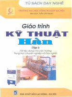
FIGURE 1.1
Key component technologies contributing to system evolution (not to scale).
days, these have been operated mostly via mechanical elements or devices
which caused inaccuracy and inefficiency, thus resulting in difficulty in
achieving a desired performance.
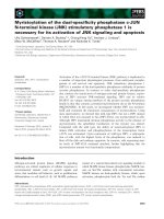
Figure 1.1 and Figure 1.2 show how the key technologies such as
mechanical, electrical, and optical have contributed to the evolution of
machines/systems in terms of “value or performance” as years have
passed [6]. As can be seen from the figure, tremendous efforts have been
made to enhance system performance by combining electrical and electronic
hardware with mechanical systems. A typical example is a gear-trained
mechanical system controlled by a hardwired controller. This mechanical
and electronic, called mechatronic configuration, consisted of two kinds of
components: mechanism, and electronics and electric hardware. Because of
10k
10k
mechanism mechanical
automation
−
411
+
analog
control
μ-processor
embedded M/C
optomechatronically
embedded system
internet
based (teleoperation)
mechatronic technology
optomechatronics technology
FIGURE 1.2
Evolution of machines.
© 2006 by Taylor & Francis Group, LLC
Introduction: Understanding of Optomechatronic Technology
3
the hard-wired structural limitation of this early mechatronic configuration,
flexibility was not embedded in most systems in those days. This kind of
tendency lasted until the mid 1970s when microprocessors came into use for
industrial applications.
The development of microprocessors has provided a new stimulant for
industrial evolution. This brought about a big change, the replacement
of many mechanical functions with electronic ones through the role of
microprocessor. This evolutionary change has opened up the era of
mechatronics, and has raised the autonomy level of machines and systems,
at the same time increasing versatility and flexibility. The autonomy and
flexibility achieved thus far, however, have a growth limited to a certain
degree, since both the hardware and software of the developed mechatronic
systems have not been developed so much as to have the capability of realizing many complicated functions autonomously while adapting to changing
environments. In addition, information structure has not been developed
to have real-time access to appropriate system data and information.
There may be several reasons for this delay. The first one may be that in
many cases mechatronic components alone may not achieve desirable
function or performance as specified for a system design. The second one is
that, although mechatronic components alone can work, the results achieved
may not be as good as required because of their low perception and
execution capability and also inadequate integration between hardware
and software. In fact, in many cases measurements are difficult or not even
feasible due to inherent characteristics of the systems. In some other cases,
the measurement data obtained by conventional sensors are not accurate or
reliable enough to be used for further processing. They can sometimes be
noisy, necessitating some means of filtering or signal conditioning. The
difficulties listed here may limit the enhancement of the functionality and
performance of the mechatronic systems. This necessitates the integration of
the mechatronic technology with other systems.
In recent years, optical technology has been increasingly incorporated at
an accelerated rate into mechatronic systems, and as a result, a great number
of mechatronic products, machines and systems with smart optical
components have been introduced into the market. There may be some
compelling reasons for this changing trend. One reason is that the optical
technology possesses unique characteristics such as noncontact/noninvasiveness visual perception, and insensitivity to electrical noise. As shown in
Figure 1.1, the contribution of the optical technology is growing and
enhances the system value and performance, since optical elements
incorporating mechatronic elements embedded in the system provide
some solutions to the difficult-to-solve technical problems. This emerging
trend demonstrates that the optically integrated technology provides
enhanced characteristics in such a way that it creates new functionalities
that are not achievable with conventional technology alone, exhibits higher
functionalities since it makes products and systems function on an entirely
different principle or in a more efficient manner, and produces high precision
© 2006 by Taylor & Francis Group, LLC
4
Optomechatronics
and reliability since it can facilitate or enable in-process monitoring and
control of the system state. Besides, the technology makes it feasible to
achieve dimensional downsizing and allows system compactness, since it
has the capability of integrating sensors, actuators, and processing elements
into one tiny unit.
Historical Background of Optomechatronic Technology
The root of the development of the optically integrated mechatronic
technology may be easily found when we revisit the historical background
of the technological developments of mechatronics and optoelectronics.
Figure 1.3 shows the development of mechatronic technology in the upper
line above the arrow and that of optical engineering in the lower line [8].
The real electronic revolution came in the 1960s with the integration of
transistor and other semiconductor devices into monolithic circuits following the invention of the transistor in 1948. Then the microprocessor was
invented in 1971 with the aid of semiconductor fabrication technology and
made a tremendous impact on a broad spectrum of technological fields. In
particular, the development created a synergistic fusion of a variety
hardware and software technologies by combining them with computer
technology. The fusion made it possible for machines to transform analog
signal into digital, to compute necessary calculations, to make decisions
based upon the computed results and software algorithms, and then to take
appropriate action according to the decision and to accumulate knowledge/data/information within their own memory domain. This new
functionality has endowed machines and systems with characteristics such
as flexibility and adaptability, and the importance of this concept has been
recognized among industrial sectors, which accelerated ever wider
applications. In the 1980s, the semiconductor technology also created
micro-electro-mechanical systems (MEMSs), and this brought about a new
dimension of machines and systems, micro-sizing their dimensions.
Another technological revolution, so-called opto-electronic integration,
has continued during the last 40-plus years ever since the laser was invented
in 1960. This was made possible with the aid of advanced fabrication
methods such as chemical vapor deposition, molecular-beam epitaxy, and
focused-ion-beam micro-machining. These methods enabled integration of
optical, electro-optic, and electronic components in a single compact device.
The charge coupled device (CCD) image sensor developed in 1974 not only
introduced computer vision technology but also opened up a new era of
optical technology along with optical fiber sensors which appeared from
1976. The optical components and devices that were developed possessed a
number of favorable characteristics, including: (1) noncontact/noninvasive;
(2) easy to transduce; (3) having a wide sensing range; (4) insensitive to
© 2006 by Taylor & Francis Group, LLC
Introduction: Understanding of Optomechatronic Technology
FIGURE 1.3
History of optomechatronics.
Source: Cho, H.S. and Kim, M.Y., IEEE Transaction on Industrial Electronics, 52:4, 932–943, 2005. q 2005 IEEE.
5
© 2006 by Taylor & Francis Group, LLC
6
Optomechatronics
electrical noises; (5) distributed sensing and communication; and (6) high
bandwidth.
Naturally, these favorable optical characteristics began to be integrated
with those of the mechatronic elements and this integration helped achieve
systems of higher performance. When a system or a machine is integrated in
this way, namely optically, mechanically, and electronically, it is called an
optomechatronic system. Looking back at the development of this system
shown in Figure 1.3, we can bring to mind a number of practical examples.
The lithography tool that fabricates ICs and other semiconductor devices
belongs to this system category: it functions through a series of elaborate
mirrors in addition to a light beam, optical units and a stepper servo
mechanism that precisely shifts the wafer from site to site. Another
representative system is the optical pick-up device mass-produced from
1982. The pickup system reads information off the spinning disc by
controlling both the up-and-down and side-to-side tracking of a read head
which carries a low-power diode laser beam focused onto the pits of the disc.
Since the early days, a great number of optomechatronic products, machines
or systems have come out at an increasingly accelerated rate, for the effects that
can be achieved with the properties of optical components are significant.
As shown in Figure 1.3, through the advancement in microsystems and the
advent of MEMS, optomechatronic technology has brought about a new
technology evolution, that is, a marriage of optics with microsystems or MEMS.
A variety of the components or systems that belong to this category have been
developed, and the atomic force microscope (AFM), optical MEMS, and optical
switch are some examples among them.
As seen from the historical perspective, the electronic revolution
accelerated the integration of mechanical and electronic components and
later, the optical revolution created the integration of optical and electronic
components. This trend enabled a number of conventional systems having
very low level autonomy and very low work performance to evolve into
those having improved autonomy and performance.
Figure 1.4 illustrates practical systems currently in use that evolved from
their original old versions. Printed circuit board (PCB) inspection was
carried out by the naked eyes of human workers using a microscope until
recently, but is now performed by a visual inspection technique. The chip
mounter or surface mounting device (SMD), originally mostly performed in
a mechanical way based on CAD drawing, is now being carried out by
integrated devices such as a part position estimator, visual sensors, and a
servo control unit. The coordinate measuring machine (CMM) appeared as a
contact then noncontact device, then became a digital electromagnetic type
and then an optical type. In recent years, the CMM is actively being
researched to introduce it as an accurate, reliable, versatile product, in which
a sensor integration technique is to be adopted, as can be seen from the
figure. The washing machine shown in Figure 1.6d also evolved from a
mechanically operated machine to one having optical sensory feedback and
intelligent control function. Table 1.1 illustrates the evolution of some of
© 2006 by Taylor & Francis Group, LLC
mounter
nozzle
PCB
illumination
camera
mechanical positioning mounter
(a) PCB inspection
Visual positioning mounter
(b) chip / SMD mounting
electron beam
touch
probe
(c) coordinate measuring machine
Optical
probe
electron gun
digital micro mirrors
lamp
fluorescent
magnetic yolk
panel
CRT
projector
R
G
B
LCD
projector
lens
DLP
projector
Introduction: Understanding of Optomechatronic Technology
Fiducial
(d) projector
FIGURE 1.4
Illustrative evolutions.
7
© 2006 by Taylor & Francis Group, LLC
8
Optomechatronics
TABLE 1.1
Evolution in Various Products
Technology/Product
Data storage disc
Printer
Projector
IC chip mounter
PCB inspection
Camera
Coordinate measuring
machine (CMM)
Technological Trend
Mechanical recording ! magnetic
recording·optical recording
Dot printer ! thermal printer/ink jet
printer ! laser printer
CRT ! LCD·DLP projector
Partially manual automated
assembly ! mechanically
automated assembly ! assembly
with visual chip recognition
Naked eye inspection !
optical/visual inspection
Manual film camera ! motorized zoom,
auto exposure, auto focusing ! digital
camera (CMOS, CCD device)
Touch probe ! optical probe !
touch probe þ visual/optical sensing
Source: Cho, H.S. and Kim, M.Y., IEEE Transactions on Industrial Electronics, 52:4, 932–943, 2005. q
2005 IEEE.
products through the presence of optomechatronic technology. In the sequel,
we shall elaborate more on this issue and utilize a number of practical
systems to characterize optomechatronic technology.
Optomechatronics: Definition and Fundamental Concept
It can be observed from the previous discussions that the technology
associated with the developments of machines/processes/systems has
continuously evolved to enhance their performance and to create new value
and new function. Mechatronic technology integrated by mechanical,
electronic/electrical, and computer technologies has been certainly taking
an important role for such evolution, as can be seen from the historical time
line of technology evolution.
To make them evolve further towards systems of precision, reliability, and
intelligence, however, optics and optical engineering technology needed to
be integrated into mechatronics, thus compensating for some limitations in
the existing functionalities and creating new ones. The optomechatronics
centered in the middle of Figure 1.5 is, therefore, a technology integrated
with the optical, mechanical, electrical, and electronic technologies.
The technology fusion in this new paradigm is termed optomechatronics or
© 2006 by Taylor & Francis Group, LLC
Introduction: Understanding of Optomechatronic Technology
9
Optics
Optom
ech
at
r
Op
t
ics
tron
lec
oe
ics
on
Optomechatronics
Mechanics
M e c h a tr o nic s
Electronics
FIGURE 1.5
The optomechatronic system.
optomechatronic technology [6, 7]. Figure 1.5 shows the integrated technologies
that can be achieved by three major technologies: optical, electrical, and
mechanical. We can see that optomechatronics can be achieved with a
variety of different integrations.
We will see in Chapter 5 that these three important combined
technologies, optoelectronics, optomechanics, and mechatronics, will be
the basic elements for optomechatronics integration. In this section, to
provide a better understanding of, and insight into, the system we will
illustrate a variety of optomechatronic systems being used in practice and
briefly review the basic roles of optical and mechatronic technologies.
Practical Optomechatronic Systems
Examples of optomechatronic systems are found in many engineering fields
such as control and instrumentation, inspection and test, optical, manufacturing, consumer and industrial electronics, MEMS, automotive, and
biomedical applications. Here, we will take only some examples of such
fields of application.
Cameras and motors are typical products which are operated by
optomechatronic components. For example, a smart camera [3] is equipped
with an aperture control and a focusing adjustment together with an
illuminometer to perform well regardless of the ambient brightness change.
With this system configuration, new functionalities are created for the
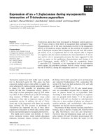
enhancement of the performance modern cameras. As shown in Figure 1.6a,
the main components of a camera are several lenses, an aperture, a shutter, and
a film or an electrical image cell such as CCD or complementary metal oxide
semiconductor (CMOS). Images are focused and exposed on the film or the
electrical image cell via a series of lenses which effect zooming and focusing of
an object. Moving the lenses with respect to the imaging plane results in
changes in magnification and focusing points. The amount of light entering
© 2006 by Taylor & Francis Group, LLC
10
laser
AFM Cantilever
position sensitive
detector
z y
AFM Tip
y
laser
upper lid
(b) atomic force microscope
(c) optical storage disk
water supply
valve
input fiber array
infrared LED
washing tank
water
output of
wash sensor
light
motor
mirror
half-mirror
3-axis piezo electric stage
(a) camera
disk
Photo-detector
lens
fibers
macro-positioner
part rack
micro-positioner
phototransistor
wash sensor
drainpipe
mechanical part
illuminator and camera
picker
=Open(down)
(e) vision guided micro
positioning system
lens
cutoff signal
MEMS Mirror
PCB
(d) modern washing machine
with optical sensory feedback
Non-interrupted signal
=Closed(up)
(f) n×n optical switching system
focusing lens
laser source
mirror (X-Y scanner)
elevator
2 mm
bending part SMA actuator
(g) fiber scope device for inspection
for microfactory
FIGURE 1.6
Illustrations of optomechatronic systems.
squeeze roll
liquid
photopolymer
platform
(h) rapid prototyping process
ng
ldi n
we ctio
e
r
i
impeder d
(i) pipe welding process
Optomechatronics
SMA coil spring
© 2006 by Taylor & Francis Group, LLC
contact tip
motorized
actuators
image guide fiber
light guide fiber
laser
sweeper
Introduction: Understanding of Optomechatronic Technology
11
through the lenses is detected by a photosensor and is controlled by changing
either the aperture or shutter speed. Recently, photosensors or even CMOS
area sensors are used for autofocusing with a controllable focusing lens.
A number of optical fiber sensors employ optomechatronic technology
whose sensing principle is based on detection of modulated light in
response to changes in the physical variables to be measured. For example,
the optical pressure sensor uses the principle of the reflective diaphragm, in
which deflection of the diaphragm under the influence of pressure changes
is used to couple light from an input fiber to an output fiber.
An atomic force microscope (AFM) is composed of several optomechatronic components: a cantilever probe, a laser source, a position-sensitive
detector (PSD), a piezo-electric actuator and a servo controller, and an x-y
servoing stage, as shown in Figure 1.6b, which employs a constant-force
mode. In this case, the deflection of the cantilever is used as input to a
feedback controller, which, in turn, moves the piezo-electric element up and
down in z, responding to the surface topography by holding the cantilever
deflection constant. This motion yields a positional variation of light spot at
the PSD, which detects the z-motion of the cantilever. The position-sensitive
photodetector provides a feedback signal to the piezo-motion controller.
Depending upon the contact state of the cantilever, the microscope is
classified into contact AFM, intermittent AFM, or noncontact AFM.
The optical disc drive (ODD) or optical storage disc is an optomechatronic
system as shown in Figure 1.6c. The ODD is composed of an optical head
that carries a laser diode, a beam focus servo that dynamically maintains the
laser beam in focus, and a fine track voice coil motor (VCM) servo that
accurately positions the head at a desired track. The disc substrate has an
optically sensitive medium protected by a dielectric overcoat and rotates
under a modulated laser beam focused through the substrate to a diffractionlimited spot on the medium.
Nowadays a washing machine effectively utilizes optoelectronic components to improve washing performance. It has the ability to feedback control
the water temperature within the washing drum and adjust the washing cycle
time, depending upon the dirtiness inside the washing water area. As shown
in Figure 1.6d, the machines are equipped with an optomechatronic
component to achieve such a function. To detect water contamination a light
source and a photo-detector are installed at the drain port of the water flowing
out from the washing drum, and this information is fedback to the fuzzy
controller to adjust washing time or water temperature [44].
The precision mini-robot equipped with a vision system [4] is carried by
an ordinary industrial (coarse) robot as shown in Figure 1.6e. Its main
function is fine positioning of the object or part to be placed in a designated
location. This vision-guided precision robot is directly controlled by visual
information feedback, independently of the coarse robot motion. The robot is
flexible and low cost, being easily adaptable to change of batch run size,
unlike the expensive, complex-and-mass production oriented equipment.
This system can be effectively used to assemble wearable computers which
© 2006 by Taylor & Francis Group, LLC
12
Optomechatronics
require the integration of greater numbers of heterogeneous components in
an even more compact and light-weight arrangement.
Optical MEM components are miniature mechanical devices capable of
moving and directing a light beam as shown in Figure 1.6f. The tiny
structures (optical devices such as mirrors) are actuated by means of
electrostatics, electromagnetics, and thermal actuating devices. If the
structure is an optical mirror, the device can move and manipulate light.
In optical networks, optical MEMS can dynamically attenuate a switch,
compensate, and combine and separate signals, all in an optical manner. The
optical MEMS applications are increasing and classified into five main areas:
optical switches, optical attenuators, wavelength tunable devices, dynamic
gain equalizers, and optical add/drop multiplexes.
Figure 1.6g illustrates a fine image fiberscope device [42] which can
perform active curvature operations for inspection of a tiny, confined area
such as a micro-factory. A shape memory alloy (SMA) coil actuator enables the
fiberscope to move through a tightly curvatured area. The device has a fine
image fiberscope of 0.2 mm outer diameter with light guides and 2000 pixels.
Laser-based rapid prototyping (RP) is a technology that produces
prototype parts in a much shorter time than traditional machining processes.
One use of this technology is stereo-lithography apparatus (SLA).
Figure 1.6h shows the SLA which utilizes a visible or ultraviolet laser and
a position servo mechanism to selectively solidify liquid photo-curable resin.
The process machine forms a layer with a cross-sectional shape that has been
previously prepared from computer-aided design (CAD) data of the product
to be produced. By repeating the forming layers in a specified direction, the
desired three-dimensional shape is constructed layer by layer. This
process solidifies the resin to 96% of full solidification. After building, in a
post-curing process the built part is put into an ultraviolet oven to be cured
up to 100%.
There are a number of manufacturing processes requiring feedback
control of in-process state information that must be detected by optoelectronic measurement systems. One such process is illustrated here to help
readers to understand the concept of the optomechatronic systems.
Figure 1.6i shows a pipe-welding process that requires stringent weld
quality control. A structured laser triangulation system achieves this by
detecting the shape of a weld bead in an on-line manner and feeding back
this information to a weld controller. The weld controller adjusts the weld
current according to the shape of element being made. In this situation, no
other effective method of instantaneous weld quality measurement
can replace the visual in-process measurement and feedback control
described here [21].
Basic Roles of Optical and Mechatronic Technologies
Upon examination of the functionalities of a number of optomechatronic
systems, we can see that there are a number of functions that can be carried
© 2006 by Taylor & Francis Group, LLC
Introduction: Understanding of Optomechatronic Technology
13
out by optical technology. The major functions and roles of optical
technology can be categorized into several functional domains as shown
in Figure 1.7 [5].
Basic Roles of Optical Technology
(1) Illumination: illumination, which is shown in Figure 1.7a, provides
the source of photometric radiant energy incident to object surfaces.
In general, it produces a variety of different reflective, absorptive,
and transmissive characteristics depending on the material properties and surface characteristics of the objects to be illuminated. The
illumination source emits spectral energy from a single wavelength
which those produces a large envelope of wavelength.
(2) Sensing: optical sensors provide fundamental information on
physical quantities such as force, temperature, pressure, and strain
as well as on geometric quantities such as angle, velocity, etc. This
information is obtained by optical sensors using various optical
phenomena such as reflection, scattering, refraction, interference,
diffraction, and so on. Conventionally, optical sensing devices are
composed of a light source, photonic sensors, and optical
components such as lenses, beam splitter, and optical fiber as
shown in Figure 1.7 b. Recently, numerous sensors have been
developed using optical fiber for its advantages in various
applications. Optical technology can also contribute to material
science. The composition of chemicals can be analyzed by
spectrophotometry, which recognizes the characteristic spectrum
of light that could be reflected, transmitted, and radiated from the
material of interest.
(3) Actuating: light can change physical properties of materials by
increasing the temperature of the material or affecting the
electrical environment. The materials which can be changed by
light are lead zirconate titanate (PZT) and SMA. As shown in
Figure 1.7c, the PZT is composed of ferroelectrics material, in
which the polar axis of the crystal can be changed by applying an
electric field. In optical PZT, an electric field is induced in
proportion to the intensity of light. The SMA is also used as an
actuator. When SMA is illuminated by light, its shape is changed
as a memorized shape due to the increase of temperature. On the
other hand, when the temperature of SMA is decreased, its shape
is recovered. The SMA is used in a variety of actuator, transducer,
and memory applications.
(4) Data (signal) storage: digitized data composed of 0 and 1 can be
stored in media and read optically as illustrated in Figure 1.7d.
The principle of optical recording is using light-induced changes
in the reflection properties of a recording medium. That is to say,
the data are carved in media by changing the optical properties in
© 2006 by Taylor & Francis Group, LLC
14
© 2006 by Taylor & Francis Group, LLC
Optomechatronics
FIGURE 1.7
Basic roles of optical technology.
Introduction: Understanding of Optomechatronic Technology
(5)
(6)
(7)
(8)
15
the media with laser illumination. Then, data reading is achieved
by checking the reflection properties in the media using an optical
pickup sensor.
Data transmitting: light is a good medium for delivering data for its
inherent characteristics such as high bandwidth unaffected by
external electromagnetic noise. Laser, a light source used in optical
communication, has high bandwidth and can contain a lot of data at
a time. In optical communication, the digitized raw data such as text
or picture are transformed into light signals and delivered to the
other side of the optical fiber and decoded as the raw data. As
indicated in Figure 1.7e, the light signal is transferred within the
optical fiber without loss by total internal reflection.
Data displaying: data are effectively understood by end users by
visual information. In order to transfer data to users in the form of an
image or graph, various display devices are used such as cathode ray
tube (CRT), liquid crystal display (LCD), light emitting diode (LED),
plasma display panel (PDP), etc. As illustrated in Figure 1.7f, they are
all composed of pixel elements consisting of three basic coloremitting cells that are red, green, and blue light. Arbitrary colors can
be made by the combination of these three colors.
Computing: optical computing is performed by using switches, gates,
and flip-flops in their logic operation just like digital electronic
computing. Optical switches can be built from modulators using
optomechanical, optoelectronic, acousto-optic, and magneto-optic
technologies. Optical devices can switch states in about a picosecond
or a thousandth of billionth of a second. An optical logic gate can be
constructed from the optical transistor. For an optical computer, a
variety of circuit elements besides the optical switch are assembled
and interconnected, as shown in Figure 1.7g. Light alignment and
waveguide are two big problems in the actual implementation of the
optical computer.
Material property variation: when a laser is focused on a spot using
optical components, the laser power is increased on a small
focusing area. This makes the highlighted spot of material change
its state as shown in Figure 1.7h. Laser material processing methods
utilize a laser beam as the energy input, and can be categorized into
two groups: (1) the method for changing the physical shape of the
materials, and (2) the method for changing the physical status of the
materials.
Basic Roles of Mechatronic Elements
The major functions and roles of mechatronic elements in optomechatronic
systems can be categorized into the following five functional domains:
sensing, actuation, information feedback, motion or state control, and
embedded intelligence with microprocessor [6].
© 2006 by Taylor & Francis Group, LLC
16
Optomechatronics
First, transducer technology used for sensing nowadays enjoys the
integrated nature of mechatronics. The majorities of sensors belong to this
category. Second, the drivers and actuators produce a physical effect such as
a mechanical movement or a change of property and condition. Third, one of
the unique functions of mechatronics is to feedback information for certain
objectives. Fourth, the control of motion or state of systems is a basic
functionality that can be provided by mechatronics. Last, a mechatronic
system implemented with a microprocessor provides many important
functions, for example, the stored or programmed control, the digital signal
processing, and the design flexibility for the whole system. In addition,
advantages of integration within a small space and the low power
consumption are attractive features.
Characteristics of Optomechatronic Technology
Based upon what we have previously observed from various optomechatronic systems, we can summarize the following characteristic points: (1)
they possess one or more functionalities to carry out certain given tasks; (2)
to produce such functionalities, several basic functional modules are
required to be appropriately combined; (3) to achieve combining functions
in a desired manner, a certain law of signal (energy) transformation and
manipulation needs to be utilized that converts or manipulates one signal to
another in a desired form, using the basic mechanical, optical, or electrical
one; (4) optomechatronic systems are hierarchically composed of subsystems, which are then composed of units or components. In other words,
elements, components, units, or subsystems are integrated to form an
optomechatronic system.
As we have seen from various illustrative examples of optomechatronic
systems discussed above, optomechatronic integration causes all three
fundamental signals to interact with each other as shown in Figure 1.8a.
Here, three signals imply three different physical variables originated
from optical, mechanical, and electrical disciplines. For instance, an
optical signal includes light energy, ray and radiation flux, mechanical
signal, energy, stress, strain, motion and heat flux, and electrical signal,
current, voltage, and magnetic flux, and so on. Depending on how
they interact, the properties of the integrated results may be entirely
different. Therefore, it is necessary to consider the interaction phenomenon
from the point of view of whether the interaction may be efficiently
realizable. Optomechatronic integration can be categorized into three
classes, depending on how optical elements and mechatronic components
are integrated. As indicated in Figure 1.8b, the classes may be divided into
the following.
(1) Optomechatronically fused type
In this type, optical and mechatronic elements are not separable in the
sense that if either are removed from the system that they constitute,
the system cannot function properly. This implies that those two separate
© 2006 by Taylor & Francis Group, LLC