AQA PHA6 b6 x TN JUN13
Bạn đang xem bản rút gọn của tài liệu. Xem và tải ngay bản đầy đủ của tài liệu tại đây (1.28 MB, 28 trang )
General Certificate of Education
Advanced Level Examination
June 2013
Physics
PHA6/B6/XTN
(Specifications A and B)
Unit 6
Investigative and Practical Skills in A2 Physics
Route X Externally Marked Practical Assignment (EMPA)
Instructions to Supervisors
Confidential
To be given immediately to the teacher(s) responsible for GCE Physics
Open on receipt
• These instructions are provided to enable centres to make appropriate arrangements for the
Unit 6 Externally Marked Practical Assignment (EMPA)
• It is the responsibility of the Examinations Officer to ensure that these Instructions to
Supervisors are given immediately to the Supervisor of the practical examination.
WMP/Jun13/PHA6/B6/XTN
PHA6/B6/XTN
2
INSTRUCTIONS TO THE SUPERVISOR OF THE EXTERNALLY
MARKED PRACTICAL EXAMINATION
General
Security/confidentiality
The instructions and details of the EMPA materials are strictly confidential. In no circumstances
should information concerning apparatus or materials be given before the examination to a candidate
or other unauthorised person.
The EMPA supplied by AQA at AS and at A2 for a given academic year must only be used in that
academic year. It may be used for practice in later academic years.
Using information for any purpose beyond that permitted in this document is potentially
malpractice. Guidance on malpractice is contained in the JCQ document Suspected Malpractice in
Examinations and Assessments: Policies and Procedures.
The Examinations Officer should give copies of the Teacher Notes (PHA3/B3/XTN and/or
PHA6/B6/XTN) to the teacher entrusted with the preparation of the examination upon receipt.
Material from AQA
For each EMPA, AQA will provide:
• Instructions to Supervisors
• Section A Task 1 and Task 2 question paper/answer booklets
• Section B EMPA written test papers.
Preparation/Centre responsibility
This practical assessment should be carried out after candidates have acquired the necessary skills
and after the appropriate sections of the specification have been taught so that candidates are familiar
with any specialist apparatus involved.
The assessment must be carried out between the dates specified by AQA.
It is the responsibility of the centre to ensure that each of the specified practical activities works with
the materials provided to the candidates.
The assessment and management of risks are the responsibility of the centre.
Practical Skills Verification (PSV)
Candidates must undertake the five practical activities specified, in order for them to demonstrate in
the EMPA that they can use apparatus appropriate to the teaching of Physics at this level. In doing
so, candidates will be familiar with the equipment and skills they will use in the EMPA. The teacher
must confirm that this requirement has been met on the front cover of the Section B written paper.
WMP/Jun13/PHA6/B6/XTN
3
Section A: Task 1 and Task 2
• Candidates should work individually and be supervised throughout. They should not discuss
their work with other candidates at any stage.
• The work can be carried out in normal timetabled lessons and at a time convenient to the
centre. Teachers will be in the best position to judge how many sessions are appropriate for
candidates in their own centre.
• The candidates’ work must be handed to the teacher at the end of each practical session and
kept securely until the next stage of assessment.
• There is no specified time limit for these tasks, however candidates should be informed by the
Supervisor of the expected timescale and timetable arrangements involved in carrying out the
EMPA. Candidates must also be instructed that all readings must be entered in the question
paper/answer booklet provided and all working must be shown. Scrap paper must not be
used.
Sharing equipment / working in groups
Candidates are to work individually. Where resources mean that equipment has to be shared, the
teacher should ensure that the candidates complete the tasks individually. Where appropriate,
spare sets of apparatus should be prepared to ensure that time is not lost due to any failure of
equipment.
Centres may choose to provide sufficient sets of apparatus for the candidates to work on Section A in
a circus format with some candidates completing the questions in reverse order. In such cases the
changeover should be carefully supervised and the apparatus returned to its original state before
being used again.
Practical sessions
Before the start of the test the apparatus and materials for each candidate should be arranged, ready
for use, on the bench. The apparatus should not be assembled unless a specific instruction to do so is
made in these Instructions.
If a candidate is unable to perform any experiment, or is performing an experiment incorrectly, or is
carrying out some unsafe procedure, the supervisor is expected to give the minimum help required to
enable the candidate to proceed. In such instances the Supervisor’s Report should be completed with
the candidate’s name and number, reporting to the Examiner the nature and extent of the assistance
given. No help may be given to proceed with the analysis of their experimental data.
Any failure of equipment which, in the opinion of the Supervisor, may have disadvantaged any
candidate should be detailed on the Supervisor’s Report.
Turn over ᮣ
WMP/Jun13/PHA6/B6/XTN
4
Section B: EMPA written test
• The Section B EMPA written test should be taken as soon as convenient after completion of
Section A.
• This test must be carried out under supervision and must be completed in a single
uninterrupted session.
• When carrying out the Section B EMPA written test, candidates should be provided with their
completed copy of Section A task 2 question paper/answer booklet.
• Supervisors should ensure that candidates understand that Section A task 2 is for reference
only and they must not make any written alterations to this previous work while undertaking
Section B.
• The duration of the Section B EMPA written test is 1 hour 15 minutes except where candidates
have been granted additional time or rest breaks.
Administration
Candidates must not bring any paper-based materials into any session or take any assessment
materials away at the end of a session. Electronic and communication devices, including mobile
telephones, iPods, MP3 players are not allowed.
Modifications
The equipment requirements for the experimental tasks are indicated in these Instructions. Centres
are at liberty to make any reasonable minor modifications to the apparatus which may be required
for the successful working of the experiment but it is advisable to discuss these with the Assessment
Adviser or with AQA. A written explanation of any such modification must be given in the
Supervisor’s Report.
Absent candidates
Candidates absent for any part of Section A should be given an opportunity to carry out the practical
exercises before attempting the Section B EMPA written test. No credit can be given for any
analysis done when evidence of the relevant practical work is not provided.
Redrafting
Candidates may make only one attempt at a particular EMPA and redrafting is not permitted at any
stage, during the EMPA.
The Supervisor’s Report
The Supervisor’s Report provided in this document should be sent to the Examiner with the scripts.
Details should be given on the Supervisor’s Report if
• any part of the equipment provided differs significantly from that specified in these
Instructions
• any help is given to candidates in the event of any failure of or difficulties with the equipment.
Supervisors must also include any numerical data that is specified in the Instructions. This may
involve the Supervisor performing an experiment before the test and collecting certain data. Such
data should be given to the uncertainty indicated. Note that the Examiners may rely heavily on such
data in order to make a fair assessment of a candidate’s work.
WMP/Jun13/PHA6/B6/XTN
5
Security of assignments
Candidates’ scripts and any other relevant materials, printed or otherwise, should be collected and
removed to a secure location at the end of each session. Under no circumstances should candidates
be allowed to remove question papers from the examination room.
Completed EMPAs are to be treated in the same manner as other completed scripts and should be
kept under secure conditions before their despatch to the Examiner.
Candidates must not be given access to their completed ‘live’ EMPA. Discussion of ‘live’ EMPA
materials is not permitted.
Submission of materials to the AQA Examiner
Once completed, each candidate’s completed EMPA should be collated in candidate number order
and in the following order
• Section A task 1
• Section A task 2
• Section B EMPA written test.
The assembled material should then be secured using a treasury tag. A copy of the Supervisor’s
Report should be sent with the scripts.
Turn over ᮣ
WMP/Jun13/PHA6/B6/XTN
6
For Section A Task 1, Question 1
Candidates are to perform two experiments involving the vertical oscillations of a spring-mass system.
Apparatus required for first experiment:
• 2 retort stands, each fitted with a boss and a clamp; one is to support the spring-mass systems and
the other to hold the vertical ruler
• digital stopwatch capable of reading to 0.1 s or 0.01 s
• some method of making a fiducial mark, at the discretion of the centre, eg ‘Post-It’ label with a
pencil mark ruled across at the median line that can be affixed to the vertical ruler
• 1 expendable steel spring; if new springs are to be used these should be briefly placed under
tension (eg of about 5 N) before use
• wooden metre ruler, as straight as possible; this is to be clamped vertically alongside the springmass system with the zero graduation at the top, the positioning should enable the reading of
r1 and r2 to be made (see diagram below)
• set square or plane mirror to eliminate parallax error when making the reading of r1 and r2
• mass hanger and slotted masses to give total mass = 200 g; this arrangement should be taped
together and labelled ‘mass M1’
• further slotted masses to give total mass = 200 g, this arrangement to be taped together and
labelled ‘mass M2’; it should be possible for this mass to be added to M1 to give a combined
mass (M1 + M2).
Set up the vertical ruler alongside the clamped spring ensuring the zero graduation is at the top, as
shown in the left-hand view in the diagram below.
zero graduation
of ruler at top
vertical ruler
clamped alongside
spring
arrangement
at start
mass M1
mass M2
note: mass M1
includes hanger
mass M1
ruler reading r1
when slotted mass
is added to hanger,
total mass suspended =
M1 = 200 g
ruler reading r2
when M2 is added,
total mass suspended =
M1 + M2 = 400 g
Ensure that the positioning of the ruler is such that the readings r1 and r2 can be made when firstly
M1 is added and then M2 is also added.
Place the fiducial mark in clear view for the candidate to use.
When they have completed part (c) of the question, candidates will disassemble the apparatus to use
in the second experiment, part (d) (see page 7).
To avoid confusion as candidates move to this second experiment, Supervisors should remove
masses M1 and M2 and the spring used in the first experiment and provide, on request, the additional
apparatus detailed on page 7.
WMP/Jun13/PHA6/B6/XTN
7
Apparatus required for second experiment:
As used in the first experiment
• 2 retort stands, each fitted with a boss and a clamp
• digital stopwatch capable of reading to 0.1 s or 0.01 s
• wooden metre ruler, as straight as possible.
Additional equipment:
• mass hanger and slotted masses to give total mass = 500 g; this arrangement should be taped
together and labelled ‘mass M3’
• mass hanger and slotted masses to give total mass = 500 g; this arrangement should be taped
together and labelled ‘mass M4’
• 2 expendable steel springs; a loop of string is to be tied at one end of each spring so that these can
be suspended from the metre ruler (see note on page 6 about new springs)
• Blu-Tack or similar
• large mass or G-clamp to stabilise the arrangement, if the need arises.
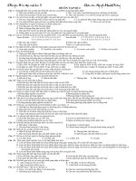
The candidates will arrange the apparatus as shown below.
metre ruler resting on horizontal arm of clamps
positioned at 10 cm and 90 cm graduations on ruler
bench level
horizontal arm of
clamp projecting
over edge of bench
side view
springs suspended by
loops of string
positioned at 40 cm
and 60 cm graduations
front view
The metre ruler is supported on the horizontal arms of the clamps which will project over the edge of
the bench. The masses M3 and M4 will be suspended from the lower ends of the springs which the
candidates will have attached to the ruler using loops of string.
A means of making the experiment stable, eg large mass or G-clamp, should be provided if the need
arises.
Before the experiment, for each set of apparatus, set the masses in vertical oscillation so that
the periods can be compared; use the Blu-Tack to make any slight adjustment necessary to
make these periods the same.
Supervisors should alert the candidates to the presence of any Blu-Tack and warn them not to
remove it.
This apparatus should be returned to its original state (ie for Experiment 1) for any candidate
following on.
Examiners require the following information.
The typical time for the energy of M3 to transfer to M4 and then back again, to ± 2 s.
Turn over ᮣ
WMP/Jun13/PHA6/B6/XTN
8
For Section A Task 1, Question 2
Candidates will investigate how the magnetic flux density varies between two bar magnets.
Apparatus required:
• 2 good quality rectangular bar magnets; these should be of approximately equal strength and
have some indication of polarity (the ALNICO type, of dimensions 50 × 15 × 10 mm, have a
dimple at the north-seeking end)
• plotting compass with two transparent faces; check that the direction indicated by these has not
been reversed
• wooden metre ruler, as straight as possible
• wooden half-metre ruler, as straight as possible
• set square
• 300 mm plastic ruler for graph drawing
• masking tape or Sellotape so that, once aligned by the candidate, the rulers can be stuck down to
the bench (or drawing board if that arrangement is used).
Dual scales on the rulers may lead to confusion (see Figure 2 of the question/answer booklet);
Supervisors may wish to tape over one scale.
Check that there is sufficient bench space for the candidates to perform this experiment; note that the
candidates will require the half-metre ruler to point away from them.
Check also that the presence of under-bench service pipes does not significantly affect the direction
in which the plotting compass points. It is suggested that the rulers are laid out as shown below with
a sheet of A3 paper (shown shaded) placed below. Providing that the compass does not deviate by
o
more than 10 from north when positioned at any point on the paper then the arrangement will be
satisfactory.
If bench space is limited or unsatisfactory the experiment can be performed on a drawing board
positioned on a stool.
Place all apparatus required on the bench before the experiment, keeping the compass away from the
magnets in case the compass becomes reverse-magnetised.
It should be explained to candidates meeting these magnets for the first time how they should
identify the north-seeking pole.
Examiners require no further information.
WMP/Jun13/PHA6/B6/XTN
9
For Section A Task 2
Candidates are to investigate the torsional oscillation of a magnet suspended in a field produced
between the poles of two further magnets, as the separation of these magnets is varied.
Apparatus required for each candidate:
• 3 good quality rectangular bar magnets of the same type as used in Section A Task 1, Question 2
• about half a metre of thread or thin string
• retort stand fitted with boss and clamp; wooden stands are preferable, but as long as the base or
rod of any metal stand does not interfere with the motion of the suspended magnet, then these are
acceptable
• digital stopwatch capable of reading to 0.1 s or 0.01 s
• wooden metre ruler, as straight as possible
• thick copper wire or similar (22 SWG or thicker) to fashion the stirrup that supports the
suspended magnet
• Blu-Tack for packing below the two magnets placed on the metre ruler
Fashion the stirrup that enables a magnet to be suspended with the longest edges parallel to the
bench and the largest faces parallel to the bench. A suggested arrangement is shown below.
Attach about 40 cm of thread to the stirrup and suspend the magnet so that it is parallel to, and about
2 cm above, the bench.
Before the examination, the Supervisor should locate a suitable position for the stand from which the
stirrup is suspended; there should be sufficient space for the metre ruler, with the graduated face
uppermost, to be positioned on the bench below the stirrup, as shown in Figure 5a in the
question/answer booklet.
The centre of the metre ruler should be directly below the suspended magnet and it should be
possible for the candidate to align the ruler with the long axis of the magnet.
Once a suitable position for the stand has been determined, the base of the stand should be taped to
the bench.
Sufficient working space should be provided to enable candidates to place the metre ruler on the
bench with its centre directly below the suspended magnet. Candidates will be instructed to rotate
the ruler about its mid-point until it is aligned with the long axis of the suspended magnet.
Examiners require no information for this question.
Turn over ᮣ
WMP/Jun13/PHA6/B6/XTN
10
General Certificate of Education
June 2013
Advanced Level Examination
PHYSICS (SPECIFICATIONS A AND B) PHA6/B6/XTN
Unit 6
SUPERVISOR’S REPORT
When completed by the Supervisor, this Report must be attached firmly to the attendance list,
or in the case of any problem affecting a particular candidate, it should be attached to the
candidate’s script, before despatch to the Examiner.
Information to be provided by the centre
Section A Task 1
Question 1 (d)
The typical time for the energy of M3 to transfer to M4 and then back again, to ± 2 s.
.............................................
Details of problems encountered by candidate...................................... candidate number .....................
...................................................................................................................................................................
...................................................................................................................................................................
...................................................................................................................................................................
...................................................................................................................................................................
...................................................................................................................................................................
...................................................................................................................................................................
...................................................................................................................................................................
...................................................................................................................................................................
...................................................................................................................................................................
...................................................................................................................................................................
...................................................................................................................................................................
Supervisor’s Signature................................................... Centre number .......................................
Date .............................................
Centres may make copies of this Supervisor’s Report for attachment to individual scripts
where necessary.
WMP/Jun13/PHA6/B6/XTN
11
Section A
Do not write
outside the
box
Task 1
Follow the instructions given below.
Give the information required in the spaces provided.
No descriptions of the experiments are required.
1
You are to perform two experiments involving the vertical oscillations of a spring-mass
system.
1 (a)
You are provided with a retort stand fitted with a clamp from which a spring is
suspended. A metre ruler has been clamped vertically alongside the spring.
Do not adjust the positions of the clamps to which the spring and the metre
ruler are attached.
on
ly
You are also provided with masses labelled M1 and M2.
1 (a) (i) Attach M1 to the lower end of the spring.
Record r1, the metre ruler reading which is at the same horizontal level as the
bottom of M1 when M1 is in equilibrium.
Te
ac
he
ru
se
1 (a) (ii) Displace and then release M1 so that it performs small amplitude vertical oscillations.
Make suitable measurements to determine T1, the time period of the oscillations.
A fiducial mark has been provided for your use.
1 (a) (iii) Add M2 to the mass already on the spring.
Record r2, the metre ruler reading which is at the same horizontal level as the
bottom of M1 when in equilibrium.
1 (a) (iv) Displace and then release the mass on the spring and make suitable measurements to
determine T2, the time period of the oscillations.
Turn over ᮣ
WMP/Jun13/PHA6/B6/XTN
12
Do not write
outside the
box
r2 – r1
(T2 –T1 ) (T2 +T1 )
Evaluate
1 (c)
Explain how you reduced uncertainty in your readings of r1 and r2.
You may use a sketch to illustrate your answer.
Te
ac
he
ru
se
on
ly
1 (b)
WMP/Jun13/PHA6/B6/XTN
13
Do not write
outside the
box
Dismantle your apparatus and place M1, M2, and the spring to one side.
Inform the Supervisor that you require the additional apparatus to complete part (d) of
this question.
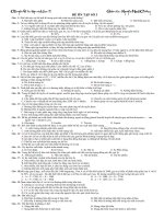
1 (d)
You are provided with an additional retort stand to which a clamp has been attached.
Adjust the height of clamps on each retort stand so the horizontal arms of these clamps
lie in the same horizontal plane, about 10 cm above the level of the bench.
Position the stands so that the arms of the clamps project over the edge of the bench, as
shown in the side view in Figure 1.
Figure 1
on
ly
metre ruler resting on horizontal arm of clamps
positioned at 10 cm and 90 cm graduations on ruler
Te
ac
he
ru
se
horizontal arm of
clamp projecting
over edge of bench
side view
bench level
springs suspended by
loops of string
positioned at 40 cm
and 60 cm graduations
front view
Join the springs to the metre ruler using the loops of string fastened at one end of each
spring, then place the ruler, with the graduated face uppermost, on the projecting arms
of the clamps. Adjust the position of the stands until the ruler is supported at the
10 cm and 90 cm graduations. Move the loops of string so that the springs are
positioned below the 40 cm and 60 cm graduations.
You are provided with masses M3 and M4.
Attach M3 to the lower end of the spring suspended below the 40 cm graduation and
attach M4 to the lower end of the spring suspended below the 60 cm graduation.
Turn over ᮣ
WMP/Jun13/PHA6/B6/XTN
14
Do not write
outside the
box
With M4 held at rest at the equilibrium position, displace M3 vertically downwards
through approximately 5 cm.
Release both masses simultaneously so that M3 performs small-amplitude vertical
oscillations.
1 (d) (i) Observe and describe the subsequent motions of M3 and M4, with particular reference
to the amplitude variations and phase relationship between the motions of the masses.
Te
ac
he
ru
se
on
ly
1 (d) (ii) Make suitable measurements to determine τ, the time for the energy of M3 to transfer
to M4 and then back again.
WMP/Jun13/PHA6/B6/XTN
15
2
Do not write
outside the
box
You are to investigate how the magnetic flux density varies between two bar magnets.
You are provided with a metre ruler and a half-metre ruler.
Place the rulers with their largest faces in contact with the bench then use the
compass, together with the set-square, to position the rulers with the alignment
shown in Figure 2.
Figure 2
N
W
E
on
ly
zero graduation on
the half-metre ruler
S
intersection of
centre lines of rulers
Te
ac
he
ru
se
zero graduation on
the metre ruler
Place the compass at the intersection of the centre line of the rulers. Make any further
small adjustment to the direction of the rulers that may be necessary so that the needle
is aligned with the centre line of the half-metre ruler.
Once in position the rulers should be taped to the bench.
Place a bar magnet on the metre ruler with the north-seeking pole at approximately the
400 mm graduations. The north-seeking pole of this magnet should point eastwards.
The magnet should be aligned with the centre line of the metre rule, as shown in
Figure 3.
Figure 3
magnet with the
north-seeking pole
at approximately the
400 mm graduation
N
W
E
S
compass placed at the
intersection of the
centre lines of the rulers
N
Turn over ᮣ
WMP/Jun13/PHA6/B6/XTN
16
Do not write
outside the
box
Place the other bar magnet at about the mid-point of the half-metre ruler with the
north-seeking pole of the magnet pointing eastwards. The centre of this magnet should
lie directly above the centre line of the half-metre ruler.
Move this magnet directly towards the compass until the needle points due north again.
2 (a) (i) Measure and record in Table 1 below, the distances x and y1 defined in Figure 4.
Figure 4
N
E
on
ly
W
S
N
Te
ac
he
ru
se
y1
N
x
2 (a) (ii) Maintaining their orientation, interchange the positions of the two magnets.
With the same x value as before, adjust the position of the other magnet until the
compass once again points due north.
Measure and record in Table 1 y2 , the distance corresponding to y1 in Figure 4 when
the magnets are interchanged.
2 (a) (iii) Calculate and record y, the mean value of the distances y1 and y2 .
2 (a) (iv) Repeat the procedure for three larger values of x to complete Table 1.
Table 1
x / mm
WMP/Jun13/PHA6/B6/XTN
y1 / mm
y2 / mm
y / mm
17
Add suitable scales to the grid below and plot a graph to show how y varies with x.
on
ly
2 (b)
Do not write
outside the
box
Te
ac
he
ru
se
y / mm
x / mm
2 (c)
Determine the gradient, G, of your graph.
Turn over ᮣ
WMP/Jun13/PHA6/B6/XTN
18
Section A
Do not write
outside the
box
Task 2
Follow the instructions given below.
Give the information required in the spaces provided.
No description of the experiment is required.
In this experiment you are to investigate the oscillation of a bar magnet suspended in a
magnetic field of variable magnetic flux density.
You are provided with a bar magnet, supported in a stirrup suspended from a retort stand.
Do not remove the stand or adjust the height of the clamp to which the stirrup is attached.
Place the metre ruler on the bench with the graduated face uppermost and the centre of
the magnet directly above the 50 cm graduation on the ruler.
Turn the metre ruler about its mid-point until it is aligned with the long axis of magnet
A, as shown in Figure 5a.
Keeping the largest surface of the magnet uppermost, the long axis of the magnet
parallel to the bench and the thread supporting the magnet vertical, displace each end
of the magnet in opposite directions so the magnet is rotated through a small angle, as
shown in Figure 5b.
on
ly
1
Te
ac
he
ru
se
Figure 5a
Figure 5b
thread
view from bench level
magnet A,
largest surface
uppermost
view from above
50
50
460 470 480 490 500 510 520 530 540
460 470 480 490 500 510 520 530 540
ruler aligned with long axis
of magnet A
1 (a)
ends of magnet A displaced in opposite
directions and thread kept vertical
Simultaneously release both ends of magnet A so that it performs small-amplitude
torsional oscillations. Make suitable measurements to determine T0 , the period of
these oscillations.
WMP/Jun13/PHA6/B6/XTN
19
1 (b)
Do not write
outside the
box
Position magnets B and C on the ruler, so that each attracts the nearest pole of magnet A.
Use Blu-Tack below magnets B and C until all three magnets lie approximately in the
same horizontal plane with their largest faces uppermost.
Do not alter the length of the thread supporting magnet A.
Adjust the positions of magnets B and C until they are equidistant from the nearer ends
of magnet A, and the separation, d, is between 50 cm and 60 cm, as shown in Figure 6,
which is not to scale.
Figure 6
magnet B
magnet A
d
magnet C
Te
ac
he
ru
se
Blu-Tack
on
ly
Not to scale
Displace magnet A as before, then release it so that it performs small-amplitude
torsional oscillations.
Measure and record the period, T, of these oscillations, then repeat the procedure for
four smaller values of d: do not use values of d less than 25 cm.
Record your measurements below.
Note that the independent variable should be recorded in the left-hand column of your
table.
Turn over ᮣ
WMP/Jun13/PHA6/B6/XTN
20
1 (c)
Do not write
outside the
box
Plot, on the grid opposite, a graph with log
log (d / cm) on the horizontal axis.
1
1
– –––) / s ) on the vertical axis and
( (–––
T
T
–2
2
2
0
Te
ac
he
ru
se
on
ly
Tabulate below the data you will plot on your graph.
WMP/Jun13/PHA6/B6/XTN
21
Do not write
outside the
box
Section B
Answer all the questions in the spaces provided. Time allowed 1 hour 15 minutes.
You will need to refer to the work you did in Section A Task 2 when answering these questions.
1 (a)
1
1
Determine the gradient, G, of your graph of log –––
– –––
against log d.
2
T
T02
1 (b)
It is suggested that the period is related to the distance by the expression
(
)
1 (b) (i) Deduce the value of n.
1 (b) (ii) Deduce the unit for k.
on
ly
1
1
–––
– –––
= kdn ,
2
2
T
T0
where k is a constant and n is an integer.
Te
ac
he
ru
se
1 (b) (iii) State and explain how you could use your graph to deduce the numerical value of k.
Turn over ᮣ
WMP/Jun13/PHA6/B6/XTN
22
2
Do not write
outside the
box
In Section A Task 1 you observed the energy transfer between masses M3 and M4
suspended by springs from a horizontal metre ruler using the apparatus shown in
Figure 7.
Figure 7
d
on
ly
horizontal arm
of clamp
mass M3
mass M4
Te
ac
he
ru
se
With the same apparatus, a student investigates how d, the horizontal distance between
the arms of the clamps on which the metre ruler is supported, affects τ, the time of
energy transfer between M3 and M4 .
The student measured the times for n energy transfers between the masses, as shown in
Table 2.
Table 2
d / cm
n
nτ/s
nτ/s
86.0
6
212
209
78.0
5
236
240
70.0
6
408
*
65.0
4
347
*
τ/s
* only one set of readings of n τ was completed for these values of d
2 (a) (i) Complete Table 2 to show the values for τ that the student obtained.
2 (a) (ii) Justify the number of significant figures you have given for the values of τ.
WMP/Jun13/PHA6/B6/XTN
23
2 (b)
1
The student claimed that these results showed that τ was directly proportional to –––
.
d2
Analyse the data in Table 2 to show whether the student’s claim is correct.
Suggest three valid control variables for the experiment.
Te
ac
he
ru
se
on
ly
2 (c)
Do not write
outside the
box
Turn over ᮣ
WMP/Jun13/PHA6/B6/XTN
24
2 (d)
Do not write
outside the
box
In a different experiment to illustrate energy transfer between oscillators, three bar
magnets are arranged as shown in Figure 8.
Figure 8
magnet B
magnet C
magnet A
magnet B is set in oscillation
on
ly
sheet of paper to prevent
magnets B and C slipping
oscillating motion is transferred to magnet C
Te
ac
he
ru
se
Magnets B and C are balanced on one edge using the repulsion produced by magnet A,
the paper below providing friction to prevent B and C slipping.
When B is set oscillating about the point of contact with the paper, the oscillating
motion is transferred within a few cycles to C, and then back again, as in your
experiment with masses M3 and M4 .
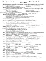
A student uses a motion sensor and a data logger to record the motion of magnet B; the
data are then exported to a computer and analysed using a spreadsheet.
Figure 9 is based on 25 000 measurements that are transferred to the data logger in
10 seconds and shows how the displacement, y, of the moving end of magnet B, varies
with time, t.
Figure 9
5
4
3
2
1
y / mm
0
–1
–2
–3
–4
–5
WMP/Jun13/PHA6/B6/XTN
0
2
4
t/s
6
8
10
25
Do not write
outside the
box
2 (d) (i) What was the sample rate of the data logger when the data displayed in Figure 9 was
being recorded?
The sample rate is then changed so that 25 000 measurements are transferred to the
data logger in 250 seconds. These results are displayed in Figure 10.
Figure 10
5
4
3
2
1
on
ly
y / mm 0
–1
–2
Te
ac
he
ru
se
–3
–4
–5
0
50
100
t/s
150
200
250
2 (d) (ii) If τ = the time for energy transfer from magnet B to magnet C and back again to B,
and T = the period of oscillations of magnet B, use Figure 9 and Figure 10 to
τ
determine ––.
T
You may assume that in both Figure 9 and 10, y has just reached a maximum value
at t = 0.
Turn over ᮣ
WMP/Jun13/PHA6/B6/XTN