AQA PHA6 b6 x TN JUN14
Bạn đang xem bản rút gọn của tài liệu. Xem và tải ngay bản đầy đủ của tài liệu tại đây (620.44 KB, 10 trang )
General Certificate of Education
Advanced Level Examination
June 2014
Physics
PHA6/B6/XTN
(Specifications A and B)
Unit 6
Investigative and Practical Skills in A2 Physics
Route X Externally Marked Practical Assignment (EMPA)
Teachers’ Notes
Confidential
The Exams Officer should make two copies of these Teachers’ Notes; one copy for the
Head of A-level Physics and one for the technician.
These copies can be released to the Head of A-level Physics and the technician at any point
following publication but must be kept under secure conditions at all times.
Teachers can have sight of the Teachers’ Notes but no further copies should be made.
Estimated entries must be submitted to AQA in order for centres to receive hard copies of the
materials to be used by candidates.
WMP/Jun14/PHA6/B6/XTN/E5
PHA6/B6/XTN
2
For Section A Task 1, Question 1 and Question 2
In Question 1, candidates will investigate capacitor discharge through a resistor. In Question 2, they
will investigate how the pd across a capacitor, C1, varies as it is discharged through a combination of
a resistor and a second (initially uncharged) capacitor, C2.
Apparatus required for each candidate:
• dc power supply, terminal pd at the discretion of the Centre; if the voltmeter is set to the
2000 mV range then one type D cell in good condition, in a suitable holder, will be adequate
• digital voltmeter with high input impedance (>1 MΩ) set to a range that will suit the power
supply the Centre wishes to use; a 31⁄2 digit LCD multimeter set to the 2000 mV range will be
adequate if a 1.5 V dry cell is used
• one 12 kΩ carbon film resistor, at least 0.25 W; the resistance of this resistor should be
concealed from the candidates
• one 1000 μF electrolytic capacitor, 10 V or higher, labelled ‘C1’
• one 2200 μF electrolytic capacitor, 10 V or higher, labelled ‘C2’
• three round sockets to be labelled ‘S1’, ‘S2’ and ‘S3’
• suitable connecting leads, including two flying leads, each terminating with a 4 mm round plug
connected as shown in the circuit diagram below; these should be labelled as indicated
• digital stopwatch capable of reading to 0.1 s or better
• card on which the calculated capacitance of C1 should be provided for the candidate’s use.
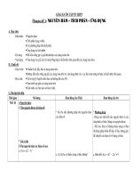
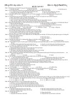
The circuit to be provided for each candidate is shown below.
flying lead 1
socket S1
flying lead 2
socket S3
2200 μF
labelled ‘C2’
socket S2
1000 μF
labelled ‘C1’
V
digital voltmeter
12 kΩ
Candidates will carry out the following procedure:
Question 1:
• Ensure that C2 remains discharged by connecting flying lead 2 to S3.
• Charge C1 by connecting flying lead 1 to S1; record voltmeter reading, ε
• Discharge C1 by connecting flying lead 1 to S2
• Starting the watch when the voltmeter reads 80% of ε determine the times for the voltmeter
reading to reach 40% of ε and 20% of ε
Question 2:
• Remove flying lead 1 from S2
• Connect flying lead 2 to S2 to avoid accidential discharge of C2 by earthing etc.
• Charge C1 by connecting flying lead 1 to S1.
• Discharge C1 by connecting flying lead 1 to S3; recording the voltmeter reading at 10 s intervals
for 60 s. During this period C2 becomes charged.
• With flying lead 2 still connected to S2 so C2 remains charged, charge and then discharge C1 for
a second time and record the voltmeter readings at 10 s intervals for a further 60 s.
WMP/Jun14/PHA6/B6/XTN
3
Testing:
In Question 1, C2 is redundant; the exercise is to charge and then discharge C1 through R.
Candidates will require the capacitance of C1 that they will use and this can be found directly using
a capacitance meter, or indirectly by measuring the time for the voltmeter reading to fall to 50% of
some initial value. The capacitance of C1 (in F) is given by
C1 =
time (in seconds) for voltmeter reading to halve
8.32 × 10³
The time for the voltmeter reading to halve will typically be between 7.5 s and 10.5 s.
In Question 2 parts (a)(i) and (a)(ii), the voltmeter reading will decrease at a decreasing rate when
the flying lead 1 is connected to S2. The pd across C2 rises to meet the (falling) pd across C1 and
when these equalise the voltmeter reading will become approximately constant; this takes about 50 s
and the reading will be equal to 30% to 35% of the initial reading.
In Question 2 parts (a)(iii) and (a)(iv) the reading falls more gradually than before because C2 is
already charged from part one. Once again, the process stops when the pd across C1 is the same
as across C2; this time the voltmeter reading will reach an approximately constant value about 50%
of the initial reading.
Place all the apparatus required on the bench before the experiments with both flying leads
disconnected and the card giving the calculated capacitance of C1 in clear view.
Examiners require no information for this question.
The following data are provided to assist in trialling the practical tasks.
Question 1
(a)
voltmeter
reading
time/s
40% of ε
9.52
20% of ε
18.67
Question 2
(a) and (b)
t/s
VA/V
VB/V
0
1.564
1.564
60
0.508
0.797
Turn over
WMP/Jun14/PHA6/B6/XTN
ᮣ
4
For Section A Task 2
Candidates are to measure the time period of a simple pendulum with an interrupted swing.
Apparatus required for each candidate:
• digital stopwatch capable of reading to 0.1 s or better
• metre ruler
• pendulum bob fastened to about 1 metre of strong thread (which should resist stretching)
• suitable fiducial mark to assist candidates to measure the period of the pendulum
• retort stand fitted with boss and clamp
• means to prevent stand movement if required.
Materials to construct assembly to support the interrupted pendulum:
• rectangular strip of thin sheet material, eg 12 mm m.d.f., suitable dimensions 300 mm × 40 mm
• between 30 mm and 40 mm of a plastic ruler (which could be cut along median line)
• one 4 mm binding (terminal) post
• small washer.
The working arrangement is shown in Figure 5 of the question/answer booklet.
The apparatus is to consist of a simple pendulum of length 0.90 m suspended so that the thread
overhangs the edge of the bench. The thread is to pass through the hole in the terminal post, so by
unscrewing the terminal the thread is released and candidates can change the effective length of
the pendulum. At a point 250 mm below the shoulder of the terminal, a section of plastic ruler is
mounted horizontally so the tapered edge of the ruler interrupts the pendulum at the mid-point of its
swing. The motion of the pendulum in a plane perpendicular to the edge of the bench will therefore
consist of half cycles of different duration.
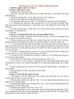
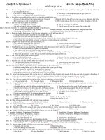
The suggested arrangement for the apparatus is described and illustrated in the diagram as follows.
Drill a suitable hole through the median line of the m.d.f. to accommodate the threaded stem of the
terminal post. Fit the terminal post in place then trim the m.d.f. so the distance between the
shoulder of the terminal post and the end of the m.d.f. is 250 mm. Glue the section of ruler in place
so that approximately 4 mm protrudes. Assemble the pendulum by passing the thread through the
hole in the terminal post and tie on the bob. Fasten a small washer to the (upper) free end of the
thread to prevent the thread becoming detached from the terminal post when the terminal is
unscrewed.
WMP/Jun14/PHA6/B6/XTN
5
Clamp the m.d.f. so that the pendulum overhangs the edge of the bench. The terminal post should
be about 100 mm above the top of the bench. Adjust the length of the pendulum so that the bob
hangs freely about 100 mm above the floor and when the thread is at rest and hanging vertically it
just touches the protruding edge of the ruler.
The metre ruler, stopwatch and fiducial mark should be placed on the bench alongside the
apparatus.
terminal post
washer
12 mm m.d.f. or similar
250 mm
section of plastic ruler
For candidates with mobility problems the apparatus can be mounted on a tall stand so that the
experiment can be carried out at bench level.
Examiners require no information for this question.
The following data are provided to assist in trialing the practical tasks.
Question 1
(a) x/m = 0.248
(b)
l/m
T /s
0.550
1.65
Turn over
WMP/Jun14/PHA6/B6/XTN
ᮣ
6
General Certificate of Education
June 2014
Advanced Level Examination
PHYSICS (SPECIFICATIONS A AND B) PHA6/B6/XTN
Unit 6
SUPERVISOR’S REPORT
When completed by the Supervisor, this Report must be attached firmly to the attendance
list, or in the case of any problem affecting a particular candidate, it should be attached to
the candidate’s script, before despatch to the Examiner.
Details of problems encountered by candidate .................................. candidate number ....................
................................................................................................................................................................
................................................................................................................................................................
................................................................................................................................................................
................................................................................................................................................................
................................................................................................................................................................
................................................................................................................................................................
................................................................................................................................................................
................................................................................................................................................................
................................................................................................................................................................
................................................................................................................................................................
................................................................................................................................................................
................................................................................................................................................................
................................................................................................................................................................
................................................................................................................................................................
Supervisor’s Signature ................................................... Centre number .......................................
Date ..........................................
Centres may make copies of this Supervisor’s Report for attachment to individual scripts
where necessary.
WMP/Jun14/PHA6/B6/XTN
7
The following instructions include the tasks that candidates will be required to complete in Section A
Task 1 and Section A Task 2. These instructions do not include all the questions that may be
asked.
Section A Task 1
1
You are to determine the resistance of a resistor R of unknown resistance using the
circuit shown in Figure 1.
Figure 1
flying lead 2
flying lead 1
on
ly
C2
socket S3
socket S1
Te
ac
he
ru
se
socket S2
C1
V
digital voltmeter
R
This circuit is used for both Question 1 and Question 2 in Section A Task 1.
Connect flying lead 2 to socket S3 as shown in Figure 1; Keep this lead connected to
S3 whilst making the measurements in Question 1.
1 (a)
Connect flying lead 1 to socket S1 so that capacitor C1 is fully charged.
1 (a) (i)
Read and record the voltmeter reading, ε.
ε = ...................................................................
Turn over
WMP/Jun14/PHA6/B6/XTN
ᮣ
8
1 (a) (ii) Remove flying lead 1 from socket S1 and connect this without delay to socket S2 so the
voltmeter reading decreases as C1 discharges through resistor R.
Start the stopwatch when the voltmeter reads 80% of ε.
Measure and record, the times at which the voltmeter reads 40% and 20% of ε.
2 (a)
Disconnect flying lead 1 from S2.
Connect flying lead 2 to S2 as shown in Figure 3; keep this lead connected to S2 whilst
making the measurements in Question 2 (unless you wish to discharge C2 in order to
repeat the question).
You are not required to take any repeat readings in Question 2(a).
Figure 3
on
ly
flying lead 1
socket S1
socket S3
C2
Te
ac
he
ru
se
flying
lead 2
C1
2 (a) (i)
V
socket S2
digital voltmeter
R
Charge C1 by connecting flying lead 1 to S1.
Record the voltmeter reading, VA.
2 (a) (ii) Disconnect the lead from S1 and without delay connect it to S3, starting the stopwatch as
you do this.
Read and record further values of VA at 10 second intervals.
2 (a) (iii) Remove flying lead 1 from S3 and connect it to S1 to recharge C1.
Record the voltmeter reading, VB.
2 (a) (iv) Disconnect the lead from S1 and without delay connect it to S3, starting the
stopwatch as you do this.
Read and record further values of VB at 10 second intervals.
You are not required to repeat the experiment but should you need to do so,
disconnect flying lead 1 from S3 and flying lead 2 from S2.
Briefly connect flying lead 2 to S3 to discharge C2 before reconnecting this lead
to S2. You may now recommence the procedure starting at part 2 (a)(i).
WMP/Jun14/PHA6/B6/XTN
9
Section A Task 2
1
In this experiment you are required to measure the time period of a pendulum with an
interrupted swing.
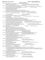
You are provided with the apparatus shown in Figure 5, including a fiducial mark.
Figure 5
Washer
on
ly
Terminal
Te
ac
he
ru
se
x
A
Piece of ruler
B
l
Pendulum bob
Turn over
WMP/Jun14/PHA6/B6/XTN
ᮣ
10
1 (a)
Measure and record x, the length of thread between the terminal and the piece of ruler.
x = ...................................................................
1 (b)
Holding the washer in one hand, unscrew the terminal. Adjust l, the length of the thread
between the piece of the ruler and the centre of the pendulum bob, until l is about 0.55 m.
Secure the thread in this position by tightening the terminal.
Make further adjustments to ensure that when the pendulum is at rest the string is
vertical along its entire length and just touches the edge AB of the ruler.
on
ly
Measure and record l.
Displace and release the pendulum so that it performs small-amplitude oscillations in a
plane perpendicular to AB.
Make suitable measurements to determine the period, T, of these oscillations.
Repeat this procedure to find T for four smaller values of l.
Te
ac
he
ru
se
Record all your observations.
Note that the independent variable should be recorded in the left-hand column of your
table.
Copyright © 2014 AQA and its licensors. All rights reserved.
WMP/Jun14/PHA6/B6/XTN