Hafez a radi, john o rasmussen auth principles of physics for scientists and engineers 11
Bạn đang xem bản rút gọn của tài liệu. Xem và tải ngay bản đầy đủ của tài liệu tại đây (739 KB, 30 trang )
8.5
Relating Angular and Linear Quantities
237
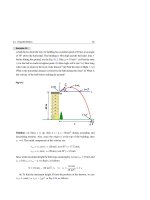
Example 8.5
A ball of mass m = 0.1 kg rotates in a circular path of radius r = 0.2 m with an
angular speed ω = 8 rad/s while being attached to two strings of equal length,
each making an angle θ = 30◦ with a vertical rod as shown in Fig. 8.9. Find the
magnitude of the tension in the two strings.
Fig. 8.9
r
T1
m
T2
T1 sin
T2 sin
T1 cos
mg
T2 cos
Solution: From the free-body diagram shown above, the vertical forces must
balance. That is:
T1 cos θ − T2 cos θ = mg
According to Eq. 8.14, the magnitude of the radial acceleration is given in terms
of the angular speed ω as ar = r ω2 . Therefore:
m r ω2 = T1 sin θ + T2 sin θ
Multiplying both sides of the first equation by sin θ and both sides of the second equation by cos θ, then adding (or subtracting) the results, we can get the
magnitude of the tension in the two strings as follows:
m
(r ω2 + g tan θ )
2 sin θ
0.1 kg
=
[(0.2 m)(8 rad/s)2 + (10 m/s2 )(tan 30◦ )] = 1.86 N
2 sin 30◦
T1 =
m
(r ω2 − g tan θ )
2 sin θ
0.1 kg
=
[(0.2 m)(8 rad/s)2 − (10 m/s2 )(tan 30◦ )] = 0.70 N
2 sin 30◦
T2 =
238
8 Rotational Motion
8.6
Rotational Dynamics; Torque
Rotational dynamics is the study of rotational motion and the causes of changes in
motion. Just as linear motion is analogous to rotational motion from a kinematics
perspective, we will see that this analogy applies also from a dynamics perspective.
We know from our everyday experience that, when an object rotates about an
axis, the rate of this rotation depends on the magnitude and direction of the exerted
force and how far this force is applied away from the rotation axis. This dependence
is measured by a vector quantity called torque (or moment) τ→ (Greek tau “τ ”).
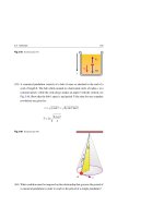
Figure 8.10a depicts a cross section of a rigid body that is free to rotate about
→
a fixed axis at O. A force F perpendicular to the axis of rotation acts on the body
at point P whose position vector from O is →
r . The smaller angle between the two
→
→
→
vectors F and r is θ. The ability of F to rotate the body about O from point P
depends on the torque τ→ as follows:
→
τ→ = →
r ×F
F
r
τ
F
θ
r
P
τ
O
O
r⊥
Rotational axis
(a)
P
(b)
(8.17)
θ
F
r
τ
O
F
θ
F
P
(c)
→
Fig. 8.10 (a) The torque →
τ produced by a force F that acts at point P on a rigid body which can rotate
freely about an axis passing through point O. (b) The torque can be written as r⊥ F, where r⊥ is the
→
moment arm of the force F. (c) The torque can also be written as r F⊥ , where F⊥ is the perpendicular
component of the force to →
r
Accordingly, its magnitude (see Chap. 2) is:
τ = r F sin θ
(8.18)
The SI unit of the torque is m.N [not to be confused with the unit of energy (1 J =
1 N.m)]. By convention, torque is positive if the force has the tendency to rotate the
8.6
Rotational Dynamics; Torque
239
object in a counterclockwise sense; and is negative if it has the tendency to rotate the
object in a clockwise sense. Also, the reverse of this convention can be used.
Based on Fig. 8.10b and c, the magnitude τ can be written as:
τ = r⊥ F (with r⊥ = r sin θ )
(8.19)
τ = r F⊥ (with F⊥ = F sin θ )
(8.20)
where the distance r⊥ is the perpendicular distance from the axis of rotation O to
the line along which the force acts (also called the lever arm, or the moment arm).
In addition, F⊥ is the component of the force perpendicular to →
r . This component is
what causes that rotation. The other component, F , is parallel to the position vector
→
r, passes through O and causes no rotation.
If two or more forces act on a rigid body, where each force tends to produce
rotation about an axis passing through some point, the net torque on the body will
be the sum of all torques:
τ→ = τ→1 + τ→2 + . . .
(8.21)
Using the sign convention introduced previously for torques, we can omit the vector
notation and write the net torque as follows:
τ = τ1 + τ2 + . . .
(8.22)
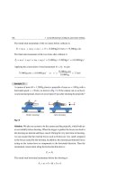
Example 8.6
Two wheels of radii r1 = 20 cm and r2 = 30 cm are fastened together as shown
in Fig. 8.11. Together, they can rotate freely about an axle O perpendicular to the
page. Two forces of magnitudes F1 = 20 N and F2 = 40 N are applied as shown
in the figure. Find the net torque on the wheel.
Fig. 8.11
F1
r1
r2
O
Rotation
axis
F2
240
8 Rotational Motion
→
Solution: Designate counterclockwise torque as positive. The force F 1 produces
a torque τ→1 that tends to rotate the wheel in a clockwise sense. Thus, the sign of
→
τ1 is negative and equal to −F1 r1 . The force F 2 produces a torque τ→2 that tends
to rotate the wheel in a counterclockwise sense. Thus, the sign of τ2 is positive
and equal to +F2 r2 . By using Eq. 8.22, the net torque is:
τ = τ1 + τ2 = −F1 r1 + F2 r2
= −(20 N)(20 × 10−2 m) + (40 N)(30 × 10−2 m)
= 8 m.N
The net torque acts to rotate the wheel in the counterclockwise sense.
8.7
Newton’s Second Law for Rotation
We will show that Newton’s second law F ∝ a for translational motion corresponds
to τ ∝ α for rotational motion about a fixed axis.
First, we consider a particle of mass m attached to one end of a rod of negligible
mass while the other end can rotate freely at point O. The mass rotates in a circle of
→
radius r under the influence of a tangential force F t , as shown in Fig. 8.12. In this
→
figure we do not display the radial force F r .
Fig. 8.12 A particle of mass
Ft
m is rotating in a circle of
m
radius r under the influence of
→
a tangential force Ft
r
O
→
According to Newton’s second law, the tangential force Ft produces a tangential
acceleration →
a t . Then:
Ft = m at
The tangential acceleration is related to the angular acceleration through the relationship at = r α, see Eq. 8.13. Thus,
8.7
Newton’s Second Law for Rotation
241
Ft = m r α
(8.23)
→
Since Ft produces a torque τ→ about the origin, this torque tends to rotate the particle
in a counterclockwise sense. The magnitude of τ→ is:
τ = r Ft
(8.24)
Substituting with Eq. 8.23 into Eq. 8.24, we get:
τ = m r2 α
(8.25)
which can be written as:
τ = I α,
I = m r2
(Single particle)
(8.26)
That is, the applied torque is proportional to the angular acceleration, and represents
the rotational equivalent of Newton’s second law. The quantity I = m r 2 represents
the rotational inertia of the particle about O and is called the moment of inertia.
The SI units of I is kg.m2 .
We can apply this result to a system of particles located at various distances from
a certain axis of rotation. For the ith particle, we apply Eq. 8.25 to get τi = (mi ri2 )α.
Then, the total torque about that axis will be τ = ( mi ri2 ) α = Iα. Thus:
τ = Iα,
I=
mi ri2
(System of particles)
Notice the analogy between the translational relation
relation τ = I α, where F ⇔ τ and m ⇔ I.
(8.27)
F = m a and the rotational
Now we consider a rigid body rotating about a fixed axis at O. We can think
of this body as an infinite number of mass elements dm of infinitesimal size,
see Fig. 8.13. Each mass element rotates in a circular path about the origin with
→
an angular acceleration →
a t produced by an external tangential force Ft .
By applying Newton’s second law to a given mass element, we get:
dFt = (dm)at
All elements of the rigid body have the same angular acceleration α. Since at = r α
is the angular acceleration of each element, then:
242
8 Rotational Motion
y
dFt
dm
r
x
O
Rotation axis
Fig. 8.13 Each element of mass dm is rotating about O in a circle of radius r under the influence of a
→
tangential force d Ft
dFt = α(dm)r
(8.28)
The magnitude of the differential torque dτ produced by dFt is:
dτ = r dFt
(8.29)
Using Eq. 8.28, the expression for dτ becomes:
dτ = αr 2 dm
(8.30)
Now we can integrate both sides of this differential relation to find the net torque
about O due to external forces as follows:
τ =α
τ
r 2 dm
(8.31)
(Rigid body)
(8.32)
which can be written as:
⎫
τ = I α, ⎬
I = r 2 dm ⎭
In this case, I = r 2 dm is the moment of inertia of the rigid body about the rotation
axis through O. All equations of the form τ = I α hold even if the external forces
have radial components, since the action of these components passes through the
axis of rotation.
8.7
Newton’s Second Law for Rotation
243
Parallel-Axis Theorem
If we calculate the moment of inertia of a body about any axis that passes through its
center of mass, then we can prove that the moment of inertia about any axis parallel
to that axis is given by:
I = ICM + M h2
(8.33)
where M is the total mass of the body and h is the perpendicular distance between
the two parallel axes. Figure 8.15 shows this for the case of a rod.
Example 8.7
A horizontal rod of uniform mass per unit length λ has a mass M and length L.
Use the relation I = r 2 dm to calculate the moment of inertia of the rod about:
(a) an axis passing through its center, and (b) an axis passing through its end. (c)
Check your result by using the parallel-axis theorem.
Solution: (a) For a uniform rod, λ = M/L. If we divide the rod into infinitesimal
elements of length dx, then the mass of each element is dm = λ dx. Figure 8.14
shows an axis through CM and the left end.
y
dm=λdx
CM
x
dx
O
L
y
h
L/ 2
dm=λdx
CM
x
O
dx
x
x
L
Fig. 8.14
For an axis passing through the CM, I in Eq. 8.32 leads to:
+L/2
ICM =
r 2 dm =
x 2 λ dx =
−L/2
=
M
L
+L/2
x3
3
−L/2
=
1
M L2
12
M
L
+L/2
x 2 dx =
−L/2
M
L
+L/2
x 2 dx
−L/2
244
8 Rotational Motion
R1
R
Thin hoop
or thin
cylindrical
shell
R2
Hollow
cylinder
I CM = 12 M ( R12 + R 22 )
ICM = M R 2
Solid
cylinder
Thin
hoop
R
ICM = 12 MR 2
R
L
ICM =
1
4
1 M L2
M R 2 + 12
R
Rectangular
plate
Solid
cylinder
or disk
a
ICM =
1
2
MR2
ICM =
b
1
12
M (a 2 + b 2 )
Thin rod
L
Thin rod
L
ICM =
1
12
Solid
sphere
M L2
ICM = 1 M L2
3
R
ICM =
2
5
M R2
R
ICM =
2
3
Fig. 8.15 Moments of inertia for some objects about specific axes
M R2
Thin
spherical
shell
8.7
Newton’s Second Law for Rotation
245
(b) For an axis passing through one end, I in Eq. 8.32 leads to:
L
I=
r 2 dm =
x 2 λ dx =
0
M
L
L
x 2 dx =
0
M
L
L
x 2 dx =
0
x3
3
M
L
L
=
0
1
M L2
3
(c) Applying the theorem I = ICM + M h2 , one can obtain the same result.
Example 8.8
A pulley of mass M = 6 kg and radius R = 20 cm is mounted on a frictionless
axis, as shown in Fig. 8.16. A massless cord is wrapped around the pulley while
its other end supports a block of mass m = 3 kg. If the cord does not slip, find
the linear acceleration of the block, the angular acceleration of the pulley, and the
tension in the cord. Take g = 10 m/s2 .
Fig. 8.16
R M
M
O
R
T
Rotation axis
T
m
a
a
m
mg
Solution: For a downward motion of the block with acceleration a, the weight
m g must be greater than the tension T, see the free-body diagram of Fig. 8.16.
Therefore, from Newton’s second law of linear motion, we get:
(1) m g − T = m a
From the free-body diagram of Fig. 8.16, we see that the torque τ that acts on
the pulley is R T. Applying Newton’s second law in angular form, Eq. 8.32, we
obtain:
τ =Iα
⇒
RT =
1
2M
R2 α
⇒
T = 21 M R α
246
8 Rotational Motion
where the moment of inertia of the pulley I =
1
2M
R2 is taken from Fig. 8.15.
The linear acceleration of the block is equal to the tangential acceleration of the
pulley, i.e., at = a. Since at = R α, then the last equation reduces to:
(2) T = 21 M a
Eliminating the tension from Eqs. (1) and (2), we get:
a=
2 × (3 kg)
2m
g=
× (10 m/s2 ) = 5 m/s2
2m + M
2 × (3 kg) + 6 kg
The angular acceleration of the pulley is thus:
α=
at
a
5m/s2
= =
= 25 rad/s2
R
R
0.2 m
We use Eq. (2) to find the tension in the cord as follows:
T = 21 M a =
1
2
× (6 kg)(5 m/s2 ) = 15 N
Example 8.9
A uniform thin rod of mass M = 2 kg and length L = 20 cm is attached from one
end to a frictionless pivot. The rod is free to rotate in a vertical plane. The rod is
released when it is in the vertical position. Figure 8.17 shows the situation when
the angle between the rod and the horizontal is θ. (a) Determine the angular acceleration of the rod as a function of θ for −90◦ ≤ θ ≤ +90◦ and find its maximum
value. (b) Find the angle where the tangential acceleration of the free end of the
rod equals g. Take g = 10 m/s2 .
Fig. 8.17
L
θ
Mg
Pivot
8.7
Newton’s Second Law for Rotation
247
Solution: (a) The moment arm of the force exerted by the pivot on the rod is
zero. Therefore, the only force that contributes to the torque is the gravitational
force M →
g with moment arm 21 L cos θ. Consequently, the angular acceleration is
not constant because the torque exerted on the rod varies with θ. Call clockwise
torques positive. Then the magnitude of this clockwise torque is:
τ=
1
2 L cos θ
Mg
By applying Newton’s second law in its angular form,
I=
1
3M
L2
τ = I α, and taking
from Fig. 8.15 for the axis of rotation at one end, we obtain:
1
2 L cos θ
α=
Thus:
Mg=
1
3M
L2 α
3g
cos θ
2L
At any angle θ, all points on the rod have this angular acceleration and the maximum value of α occurs at θ = 0. Thus:
αmax =
3g
3(10 m/s2 )
cos 0◦ =
= 75 rad/s2
2L
2(20 × 10−2 m)
The dependence of α on the angle θ indicates that the angular acceleration starts
from zero when θ = 90◦ , then increases with decreasing θ, becomes maximum of
75 rad/s at θ = 0, then decreases for negative values of θ, and reaches zero again
at θ = −90◦ .
(b) To find the tangential acceleration of the free end of the rod at any angle θ,
we use the relation at = L α and substitute with α to get:
at = L α = 23 g cos θ
Note that at does not depend on the length of the rod L. Now, setting at = g in
the previous relation, we find the value of θ to be:
cos θ =
2
3
⇒
θ = cos−1
2
3
= 48.2◦
248
8.8
8 Rotational Motion
Kinetic Energy, Work, and Power in Rotation
Rotational Kinetic Energy
Analogous to translational kinetic energy 21 mv 2 , an object that rotates about an axis
is said to have rotational kinetic energy. Using this analogy between translational
and rotational motions, where m ⇔ I and v ⇔ ω, one would expect that the rotational
kinetic energy will be given by the expression 21 Iω2 . We can show that this expression
is indeed true.
Consider the rigid body of Fig. 8.13 to be a collection of tiny particles rotating
about a fixed axis with angular speed ω. If the ith particle has a mass mi , distance ri
from the axis of rotation, and tangential speed vi = ri ω, then its kinetic energy is:
Ki = 21 mi vi2 = 21 mi ri2 ω2
(8.34)
The total kinetic energy of the rotating body will be:
K=
Ki =
1
2
mi ri2 ω2
(8.35)
Since mi ri2 is the moment of inertial of the rigid body and tends to r 2 dm for a
continuous mass distribution, then as expected we get:
KR = 21 I ω2
(Rotational kinetic energy)
(8.36)
We refer to KR as rotational kinetic energy, which has the units of energy.
Example 8.10
Figure 8.18 shows three tiny spheres, each of mass M, are fastened by three identical rods each of mass m and of length L. The system is allowed to rotate with an
angular speed ω about an axis that is perpendicular to the page and passes through
O. Find the moment of inertia and the rotational kinetic energy about this axis.
Fig. 8.18
M
L m
M
L
m
O
L
m
M
Solution: Using I from Eq. 8.27 and taking 13 m L 2 as the moment of inertia of
each rod about O, the system’s moment of inertia will be:
8.8
Kinetic Energy, Work, and Power in Rotation
249
I = 3(M L 2 ) + 3( 13 m L 2 ) = (3M + m)L 2
Therefore, the rotational kinetic energy of the system about O will be:
KR = 21 I ω2 = 21 (3M + m)L 2 ω2
Example 8.11
A block of mass m = 2 kg rests on an inclined plane of angle θ = 30◦ . The block
is connected by a cord of negligible mass that is wrapped around a pulley of mass
M = 2.5 kg and radius R = 0.8 m, see Fig. 8.19. The block slides on the incline
against a frictional force f of 0.5 N, and the pulley rotates without friction about its
axis. How fast will the block be moving after sliding a distance d = 1.5 m along
the incline?
d
m
m
R
M
f
Fig. 8.19
Solution: The work done by the frictional force W should be equal to the change
in the total energy E of the block-pulley system. Thus:
W=
E = Ef − Ei
where Ei = Ki + (KR )i + Ui and Ef = Kf + (KR )f + Uf are the initial and
final total energies of the system, respectively. If we assign a zero value for the
gravitational potential of the block at the final position, then Ui = m g(d sin θ )
and Uf = 0. Also, (KR )i = 0 and (KR )f = 21 Iω2 , where I = 21 M R2 for a disk
rotating about its central axis. In addition, Ki = 0 and Kf = 21 mv 2 . Using these
relations and substituting with W = − f d and ω = v/R into the last equation, we
get:
250
8 Rotational Motion
−f d = [ 21 m v 2 + 21 ( 21 M R2 )(v/R)2 + 0] − [0 + 0 + m g d sin θ ]
By rearranging the terms, we have:
v=2
(m g sin θ − f )d
[(2 kg)(9.8 m/s2 ) sin 30◦ − 0.5 N](1.5 m)
=2
2m + M
2 × (2 kg) + (2.5 kg)
= 2.93 m/s
Work done in Rotational Motion
We assume that the rotation of the rigid body in Fig. 8.20 is produced by an external
→
force F that acts at a point P, which is at a distance r from the rotational axis
→
through O. The radial component of F does not cause rotation, because it has a zero
moment arm, while the tangential component Ft = F sin φ does cause rotation. The
→
differential work done by F on the rigid body as it rotates through an infinitesimal
distance ds = r dθ about O is:
→
dW = F • d →
s = Ft d s = F sin φ d s = F sin φ r dθ
Fig. 8.20 A rigid body rotates
(8.37)
F
about an axis through O under
the action of a single external
→
force F acting at point P
O
r ds
dθ
P
r
φ
Rotation axis
→
Since the magnitude of the torque due to F about O is τ = Ft r, then:
dW = τ dθ
(8.38)
This is the rotational version of the one-dimensional relation dW = F ds, namely
F ⇔ τ and s ⇔ θ. For a single force, we use τ = I α = I dω/dt and the chain rule
of differentiation to get:
dW = τ dθ = I
dω dθ
dω
dω
dθ = I
dθ = I
ω dθ = Iω dω
dt
dθ dt
dθ
(8.39)
8.8
Kinetic Energy, Work, and Power in Rotation
251
By integrating Eq. 8.39, we obtain the total work as follows:
ωf
θf
W=
τ dθ
or
W=
ωi
θi
The relation W =
Iω dω = 21 Iωf2 − 21 Iωi2 =
KR
(8.40)
KR is the work-energy principle for rotational motion of a rigid
body about a fixed axis.
Power in Rotational Motion
The rate of work done at time t, dW /dt, or the instantaneous power P, is obtained
from Eq. 8.38 as follows:
P=
dW
= τω
dt
(8.41)
The right-hand side of this expression is the rotational version of the linear-motion
equation P = Fv, where F ⇔ τ and v ⇔ ω.
Example 8.12
A disk of mass M = 0.2 kg and radius R = 5 cm is attached coaxially to the massless shaft of an electric motor, see Fig. 8.21. The motor runs steadily at 900 rpm
and delivers 2 hp. (a) What is the angular speed of the disk in SI units? (b) What
is the rotational kinetic energy of the disk? (c) How much torque does the motor
deliver?
Fig. 8.21
R
M
Motor
Solution: (a) The angular speed of the motor of the disk is:
252
8 Rotational Motion
ω = 900
rev
min
min
60 s
2π rad
rev
= 94.2 rad/s
(b) The rotational kinetic energy of the disk is:
KR = 21 Iω2 =
1
2
1
2M
R2 ω 2
= 41 (0.2 kg) × (0.05 m)2 (94.2 rad/s)2 = 1.11 J
This is the amount of energy needed to bring the disk from rest to the angular
speed ω = 94.2 rad/s.
(c) The power delivered by the motor to maintain a constant angular speed
ω = 94.2 rad/s for the disk and to oppose all kinds of friction is:
P = 2 × (746 W) = 1,492 W
Using Eq. 8.41, P = τ ω, we can find the torque as follows:
τ=
8.9
P
1,492 W
=
= 15.8 m.N
ω
94.2 rad/s
Rolling Motion
Rolling as Rotation and Translation Combined
Assume that the wheel of Fig. 8.22 is rolling on a flat surface without slipping, and
that its axes of rotation always remain parallel. In this figure, point Q on the rim of
the wheel moves in a complex path called a cycloid while its center of mass moves
in a straight line.
Fig. 8.22 When a wheel rolls
without slipping on a flat
Q
Path of
the CM
Path of Q
surface, each point on the
circumference (such as point
Q) traces out a cycloid, while
the center of mass (CM) traces
out a straight line
Q
CM
CM
CM
Q
8.9
Rolling Motion
253
Now, consider a wheel of a bicycle of radius R rolling without slipping on a
horizontal surface at as shown in Fig. 8.23. Initially, the two points P and P coincide,
where P is the point of contact and P is a point on the rim of the wheel.
Fig. 8.23 When a wheel rolls
t =0
Time t
through an angle θ due to a
ω
rotation about the center of
P′
mass CM, its CM moves a
linear distance s = Rθ
θ
CM
ω
R
CM
s
P′
P
P
s
During a time interval t, both the point of contact P and the center of mass CM
move a linear distance s; while the point on the rim P moves an arc length s that
subtends an angle θ at CM. Thus:
s=rθ
Consequently, the linear speed of the center of mass will be given by:
vCM =
dθ
ds
=R
= Rω
dt
dt
(8.42)
where ω is the angular speed of the wheel about its center of mass.
Rolling as Pure Rotation
To compare rolling-without-slipping motion with pure rotational motion, we consider
Fig. 8.24. In this figure, the point of contact P is instantaneously at rest and the wheel
rotates about an axis passing through this point. Since the point CM is at a distant R
from P, and we proved that the CM has linear velocity vCM = R ω, then, in order
to preserve Eq. 8.42, the instantaneous angular velocity about P must be the same as
the instantaneous angular velocity ω about CM. In addition, the linear speed of point
Q must be 2vCM .
As a result, rolling on a flat surface without slipping is equivalent to experiencing
pure rotation about an axis through the point of contact P. Therefore, we can express
the rolling kinetic energy of the wheel as:
KRoll = 21 IP ω2
(8.43)
254
8 Rotational Motion
Fig. 8.24 Rotation about an
Q
2
CM
CM
R
axis through P with an angular
velocity ω is equivalent to
R
rotation about the CM with the
same angular velocity
CM
P
Rotation about P
where IP is the moment of inertia of the wheel about an instantaneous axis of rotation
through P. By applying the parallel-axis theorem, we substitute IP = ICM + M R2
into Eq. 8.43 to obtain:
KRoll = 21 ICM ω2 + 21 M R2 ω2
By using vCM = R ω, the relation leads to:
2
KRoll = 21 ICM ω2 + 21 MvCM
(8.44)
Based on this relation, it seems natural to consider this type of rolling as a combination
of rotational and translational motions. This consideration is explained graphically
in Fig. 8.25.
Q
Q
Q
2
CM
CM
CM
M
CM
CM
CM
P
P
Pure rotation
CM
CM
Pure translation
CM
CM
P
0
Rolling
Fig. 8.25 Rolling without slipping can be considered as a combination of pure rotation and pure translation
8.9
Rolling Motion
255
Rolling with Friction
When the linear speed vCM or the angular speed ω of a wheel changes, then a frictional
force tends to slide the wheel at the point of contact P. Before sliding occurs, this
frictional force is a static force fs . Right on the verge of sliding, this frictional force is
a maximum static force fs,max . When sliding occurs, this frictional force is a kinetic
force fk .
Figure 8.26a shows a wheel being rotated faster and faster (ω increases). The
increase in ω tends to slide the point of contact P to the left. In Fig. 8.26b, the wheel
tends to rotate more slowly, and the decrease in ω tends to slide the point of contact
P to the right.
Figure 8.26c shows a wheel rolling down an incline without sliding. The weight
M→
g at its center cannot cause rotation about the CM. Since M →
g tends to slide the
→
wheel down the incline, a frictional force f s must act at the point of contact P to
oppose the sliding tendency; and this force has a moment arm about the center of
mass.
fS
CM
CM
P
fS
CM
fS
CM
CM
CM
P
Mg
P
increases
decreases
(a)
(b)
(c)
Fig. 8.26 (a) A wheel rolls horizontally without sliding while increasing its angular speed. The frictional
→
force f s acts at P to the right in order to oppose the sliding tendency. (b) Just like in (a) but with a decreasing
→
angular speed. (c) A wheel rolls without sliding on an incline. The frictional force f s acts at P to oppose
the sliding tendency due to the wheel’s weight M →
g
Example 8.13
A disk of mass M = 1.5 kg and radius R = 8 cm rolls horizontally without sliding
with a center-of-mass speed vCM = 4 m/s. (a) What is the angular speed of the
disk? (b) What is the kinetic energy of the rolling disk?
256
8 Rotational Motion
Solution: (a) Using Eq. 8.42, we have:
ω=
vCM
4 m/s
=
= 50 rad/s
R
8 × 10⁻² m
8 rev/s
(b) The rolling kinetic energy of the disk is:
2
KRoll = KR + K = 21 ICM ω2 + 21 MvCM
=
1
2
1
2M
2
R2 ω2 + 21 MvCM
= 41 (1.5 kg) × (0.08 m)2 (50 rad/s)2 + 21 (1.5 kg)(4 m/s)2 = 18 J
Example 8.14
A solid sphere of mass M and radius R rolls without sliding when released from
rest at the top of a frictional plane having a height h and inclination angle θ, see
Fig. 8.27. The sphere starts at the top of the inclined plane and rolls to the bottom
of the incline. Find the speed and acceleration of the sphere’s center of mass when
it reaches the bottom of the incline.
Fig. 8.27
M
R
h
y
d
x
CM
Solution: Generally, the rolling kinetic energy of the sphere is:
2
KRoll = KR + K = 21 ICM ω2 + 21 MvCM
Using vCM = Rω and ICM = 25 M R2 for a solid sphere, we can express KRoll as
a function of vCM throughout the relation:
KRoll =
2
7
10 MvCM
We define the bottom of the incline to have zero gravitational potential energy.
When rolling without sliding, the center of the sphere falls a vertical distance h,
and the conservation of mechanical energy gives:
8.9
Rolling Motion
257
Kf + Uf = Ki + Ui
where Kf = KRoll , Uf = 0, Ki = 0, and Ui = M g h. Thus:
2
7
10 MvCM
+ 0 = 0 + M gh
Hence, we can express the dependence of vCM on h as follows:
vCM =
10
7 gh
Notice that this is less than the speed 2gh when an object slides on a frictionless
incline without rolling (see Examples 5.5 and 6.8).
Using the kinematic equation v 2 = v 2◦ + 2a(x−x◦ ) for the translational motion
of the sphere along the incline, with v ≡ vCM , v◦ = 0, a = aCM , and (x − x◦ ) =
d = h/ sin θ, we have:
h
10gh
= 0 + 2 aCM
7
sin θ
aCM = 57 g sin θ
Notice also that this is less than the acceleration g sin θ when an object slides
down a frictionless incline without rolling (see Example 5.5).
The independence of vCM and aCM on R and M indicates that all homogeneous
solid spheres experience the same speed and acceleration on a given incline.
Example 8.15
Three objects (a solid sphere, a disk, and a thin hoop) each having a mass M are
at rest at the same height h. At the exact same instant, these objects start to roll
without sliding down the incline of Fig. 8.28. In what order do they arrive at the
bottom?
Fig. 8.28
Hoop
M
Disk
M
Sphere
M
h
θ
258
8 Rotational Motion
Solution: For the given list of objects, we set ICM = βM R2 , where β = 0.4 for
the sphere, β = 0.5 for the disk, and β = 1 for the thin hoop. Therefore, using
KRoll = 21 ICM ω2 = M g h and vCM = Rω, the speed of the center of mass of any
one of these objects at the bottom of the incline will be:
⎧
⎪
⎪
⎨ 0.4 (for a sphere)
2gh
vCM =
, β = 0.5 (for a disk)
⎪
β +1
⎪
⎩1
(for a hoop)
Note that vCM does not depend on the object’s mass M or radius R, but only depends
on the shape (through the parameter β) and the height h. Moreover, according to
the value of β, the sphere will attain the largest value of vCM , followed by the
disk, and finally the hoop will attain lowest value of vCM , see Fig. 8.28.
In all cases, the acceleration of the center of mass is given by:
aCM =
g sin θ
(1 + β)
This is less than g sin θ for the case of a box that slides down a frictionless incline
of the same angle.
Table 8.2 summarizes the angular quantities and their linear analogs.
Table 8.2 Analogy between some linear and angular quantities and their connecting relations
Linear
Angular
Connecting relation
x
θ
x = rθ
v
ω
v =rω
a
α
at = r α
m
I
I=
F
τ
τ = r F sin θ
K = 21 mv 2
KR = 21 Iω2
W = Fd
W = τθ
P = Fv
P = τω
F = ma
τ = Iα
m r2
8.10
8.10
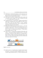
Exercises
259
Exercises
Section 8.1 Radian Measures
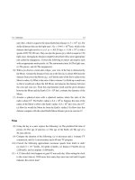
(1) As fractions of π and as numerical values, express the following angles in
radians: 30◦ , 45◦ , 60◦ , 90◦ , 180◦ , 270◦ , 360◦ .
(2) The Moon, which is 3.8 × 10⁵ km away from the Earth, subtends an angle of
about 0.4◦ to us. Estimate the radius of the Moon.
(3) A circle has a radius of 2 m. (a) What angle in radians and degrees is subtended
by an arc that is 1.5 m in length? (b) What arc length is subtended by an angle
of 1.2 rad between two radii in this circle?
(4) Through how many revolutions must a car wheel turn if the wheel has a radius
of 0.5 m and the car travels 2 km?
Section 8.2 Rotational Kinematics; Angular Quantities
(5) A drill starts from rest and after 4.5 s reaches a rate of 4 × 10⁴ rev/min. What
is the drill’s average angular acceleration?
(6) A motor rotates at a rate of 9 × 10³ rpm. When the motor is turned off, it takes
5 s to stop rotating. What is the average angular acceleration during this period?
(7) A player throws a baseball in a straight line towards a target at a speed of
90 km/h. While traveling, the ball spins at a rate of 1,800 rev/min. If the target
is 10 m away, how many revolutions does the ball make on its way to the target?
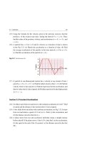
(8) A reference line in a rotating fan has an angular position given by θ = 4t 2 −
14t + 6, where θ is in radians and t is in seconds. (a) Find ω and α as a function
of time. (b) Find the times when the angular position θ and the angular velocity
ω become zero.
(9) A wheel rotates with an angular acceleration α = 6at − 2b. At t = 0, the wheel
has an angular speed ω◦ and angular position θ◦ . Write down the equations for
the angular speed and angular position as a function of time t.
(10) A wheel with six spokes is rotating at an angular speed ω = 240 rev/min about
an axle passing through its central axis at O, see Fig. 8.29. A dart of length
L = 10 cm is shot parallel to the wheel’s axle towards the wheel. Assume the
dart and the spokes are very thin. (a) What is the minimum speed that the dart
must have in order to miss any one of the spokes? (b) Does it matter where
between the axle and the rim of the wheel you must aim the dart?
260
8 Rotational Motion
Fig. 8.29 See Exercise (10)
L
O
Axle
ω
Section 8.3 Constant Angular Acceleration
(11) If the angular accelerations in Exercises 5 and 6 are constant, then find the
change in angle through the corresponding rotational period. Provide your
answer in radians, fractions of π, revolutions, and degrees.
(12) A wheel turning at an angular speed of 20 rev/s is brought to rest after 40 rev
under a constant angular deceleration. (a) What is its angular deceleration?
(b) How long does it take to stop?
(13) A car motor slows down from 5 × 10³ rpm to 2 × 10³ rpm in 2 s under a
constant angular deceleration. (a) What is its angular deceleration? (b) Find the
total number of revolutions of the motor in this period.
(14) A fan originally turning at 15 rev/s decelerates with α = −4 rad/s2 . (a) How
long does the fan take to stop? (b) How many revolutions does it turn during
this time period?
(15) A centrifuge rotates at an angular speed of 3.6 × 10³ rev/min. When the centrifuge is turned off, it rotates 60 rev before coming to test. What is its angular
deceleration? Assume it to be constant.
Section 8.4 Angular Vectors
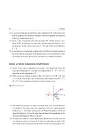
(16) A wheel is mounted on fixed supports that are on a turntable that rotates about its
axle with an angular speed ω1 = 3 rad/s, see Fig. 8.30. The turntable is rotating
horizontally at an angular speed ω2 = 4 rad/s. Take the unit vectors along x, y,
→ →
→
→
→
and z as i , j , and k , respectively. (a) What are the directions of ω
1 and ω 2
at the instant shown in the figure? (b) Find the magnitude and direction of the
→
resultant angular velocity ω
at the instant shown in the figure. (c) Find the
→
magnitude and direction of the angular acceleration of the wheel α
1 at any time
and then at the instant shown in the figure.
8.10
Exercises
261
Fig. 8.30 See Exercise (16)
z
ω1
y
x
ω2
Section 8.5 Relating Angular and Linear Quantities
(17) A wheel 0.4 m in diameter rotates uniformly at an angular speed of 3.6 ×
102 rev/min. (a) What is its angular speed in rad/s? (b) Find the linear speed
and acceleration of a point on its rim.
(18) Figure 8.31 shows a synchronized analog 12-hour clock. Find the angular velocity of: (a) the second hand, (b) the minute hand, and (c) the hour hand. (d) Find
the angular acceleration of each hand.
Ho
urs
Fig. 8.31 See Exercise (18)
ds
Minutes
Se c o n
(19) In exercise 18, assume that the radii of the second hand, minute hand, and hour
hand are 20, 15, and 10 cm, respectively. Find the linear speed of the tip of each
hand.
(20) A merry-go-round completes one revolution in 1.5 s. (a) What is the linear
speed of a child seated 3 m from the center? (b) Find the magnitude of the
child’s tangential and radial accelerations.