Hafez a radi, john o rasmussen auth principles of physics for scientists and engineers 12
Bạn đang xem bản rút gọn của tài liệu. Xem và tải ngay bản đầy đủ của tài liệu tại đây (479.28 KB, 20 trang )
8.10
Exercises
267
and direction of the speed and acceleration of a point on the top of the cylinder?
(c) What is the kinetic energy of the rolling cylinder?
(42) A thread of negligible mass is wound around a cylinder of mass M = 4 kg and
radius R = 2 cm. If the thread is unwound under a constant force of magnitude
F = 30 N and the cylinder rolls without sliding, as shown in Fig. 8.41. (a) What
is the direction of the frictional force? (b) What is acceleration of the center of
mass? (c) What is the value of the frictional force?
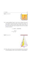
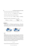
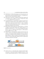
Fig. 8.41 See Exercise (42)
F
M
R
CM
a CM
(43) A hoop slides when projected horizontally at time t = 0 with an initial speed
v◦ . The frictional force causes the hoop to slow down and acquire an angular
speed. Show that the hoop stops sliding and starts rolling when it has a speed
v◦ /2 at time t = Mv◦ /2f , see Fig. 8.42.
t=0
Fig. 8.42 See Exercise (43)
t = M v /2 f
v
°
°
M
v
R
CM
f
°
v
°
CM
1
2
v
°
f
(44) A ball of radius r and mass m starts from rest and rolls without slipping on a
track in the shape of a quarter circle of radius R, as shown in Fig. 8.43. Use
conservation of mechanical energy to show that the ball’s speed at the lowest
√
point b is vb = 10g (R − r) /7.
(45) A yo-yo of mass M and moment of inertia I has an axle of radius R. One end
of a light string, assumed with negligible thickness, is tied to the axle and then
wound several times around it. For idealized yo-yo, the thickness of wounded
string can be neglected. While holding the other end of the string, the yo-yo
268
8 Rotational Motion
is released from rest, dropping as the string unwinds. Show that the linear acceleration, angular acceleration, and tension in the string of the yo-yo are given
by:
a=
Mg
g
g
, T=
, α=
2
1 + I/MR
R + I/MR
1 + MR2 /I
a =0
Fig. 8.43 See Exercise (44)
r
a
R
R
b
9
Angular Momentum
In the previous chapter, we dealt with the kinematics and dynamics of the rotation of
an extended object about a fixed axis. The rotational motion was analyzed in terms
of Newton’s second law for rotation as well as rotational kinetic energy.
In this chapter, we introduce the concept of angular momentum, a quantity
that plays a key role in rotational dynamics. Using classical physics, we saw
how linear momentum was conserved. Similarly, we will see how the conservation of
angular momentum is a fundamental law in rotational dynamics, and in further studies (not introduced in this book) can be proved to be equally valid for relativistic and
quantum physics.
9.1
Angular Momentum of Rotating Systems
9.1.1
Angular Momentum of a Particle
Figure 9.1 depicts a particle of mass m that has a momentum →
p = m→
v and a position
→
vector r that is measured with respect to an origin O of an inertial frame. The angular
→
momentum L of this particle about the origin O is defined by the vector product:
→
L =→
r ×→
p
(9.1)
→
Following the right-hand rule introduced in Chap. 2, the direction of L is perpendicular to the plane containing the two vectors →
r and →
p as shown in Fig. 9.1 and its
magnitude is given by:
L = r p sin θ = r p⊥ = r⊥ p
H. A. Radi and J. O. Rasmussen, Principles of Physics,
Undergraduate Lecture Notes in Physics, DOI: 10.1007/978-3-642-23026-4_9,
© Springer-Verlag Berlin Heidelberg 2013
(9.2)
269
270
9 Angular Momentum
Fig. 9.1 The angular
z
→
momentum L of a particle of
mass m and momentum →
p
L r p
located at position →
r is
→
defined by L = →
r ×→
p
o
y
p
r
m
x
where θ is the angle between →
r and →
p . In addition, p⊥ = p sin θ and r⊥ = r sin θ are
→
→
the components of p and r perpendicular to →
r and →
p, respectively. It follows that
L = 0 when →
r is parallel or antiparallel to →
p (θ = 0 or θ = 180◦ ). The SI unit of L is
kg.m2 /s (or J.s).
To find the relation between angular momentum and torque, we differentiate
Eq. 9.1 with respect to time as follows:
→
d (→
d→
dL
r ×→
p ) → d→
p
r
=
=r ×
+
×→
p
dt
dt
dt
dt
→
Using Newton’s second law F = d →
p /dt and the definition of net torque τ→ =
→
→
r × F , we see that the first term is just τ→. The second term is zero since
d→
r /dt × →
p = v→ × (mv→) = mv→ × v→ = 0. Therefore:
→
dL
τ =
dt
→
(Single particle)
(9.3)
That is, the net torque acting on a particle is equal to the time rate of change of
the particle’s angular momentum. The expression 9.3 is the rotational analogous to
→
→
→
F = d→
p /dt in the case of linear motion, where F ⇔ τ→ and →
p ⇔L .
For a particle of mass m moving with a constant speed v in a circular path of
→
radius r, i.e. v = rω, the magnitude of the orbital angular momentum L is constant
and given by:
L = rmv sin 90◦ = mvr
⇒
L = Iω
(9.4)
where I = mr 2 is the moment of inertia of the particle. Application of the right-hand
→
rule shows that the direction of L is also constant and perpendicular to the plane of
the circle, although the direction of →
p = mv→ keeps changing.
9.1 Angular Momentum of Rotating Systems
9.1.2
271
Angular Momentum of a System of Particles
→ →
→
Consider a system made of n particles having angular momenta L 1 , L 2 , . . . , L n .
Regardless of whether these particles are loosely bound, or tightly bound together
→
(as in a rigid body), or free, the total angular momentum L is always:
→
→
L i , (i = 1, 2, . . . , n)
L =
(9.5)
If we differentiate this equation with respect to time, we get:
→
→
dL
=
dt
dL i
=
dt
τ→i , (i = 1, 2, . . . , n)
(9.6)
Based on Newton’s third law, the sum of all internal torques must add to zero due to
the cancelation effect of all internal forces on the system. Therefore, the net torque
on the system is only due to all external torques, and Eq. 9.6 reduces to:
τ→ext
→
dL
=
dt
(System of particles)
(9.7)
→
where τ→ext and L are calculated with respect to a fixed point in an inertial frame.
→
→
This is the rotational analogue to Fext = dP/ dt in the case of linear motion, where
→
→
Fext ⇔ τ→ext and →
p ⇔L.
We can prove that Eq. 9.7 is valid for a fixed point on the center of mass of the
system, even if the CM is accelerating. Thus:
τ→CM
9.1.3
→
dL CM
(Even if CM is accelerating)
=
dt
(9.8)
Angular Momentum of a Rotating Rigid Body
Consider a rigid body rotating with an angular speed ω about a fixed axis; say the
z-axis is as shown in Fig. 9.2. A typical mass element mi of the rigid body moves
with a speed vi around the z-axis in a circular path of radius ri , i.e. vi = ri ω. If
the position of this element is measured with respect to an origin O, then with the
use of ri we will be able to find the component of the angular momentum about the
rotational axis, which is the z-axis in this case.
272
9 Angular Momentum
Fig. 9.2 A rigid body rotates
z
about the z-axis with an
angular speed ω. The
component of the angular
momentum will be along the
L
z-axis
ri
pi
mi
x
o
y
The z-component of the angular momentum of this element is:
Li = ri mi vi =
mi ri2 ω
→
→
where the vector L i is directed along the z-axis just like the vector ω
. The total
→
component of the angular momentum about the rotational axis is the sum of all L i
and denoted by Lz . Thus:
Lz =
Li =
mi ri2 ω =
mi ri2 ω
Since
mi ri2 → ∫ r 2 dm, which is the moment of inertia of the body about the
z-axis (see Chap. 8), then the above relation reduces to:
Lz = Iω
(Rigid body)
(9.9)
Note that choosing any point on the z-axis and using that point as the origin O would
yield the same Eq. 9.9. Accordingly, Eq. 9.7 will take on the following form for any
rigid body:
τext =
dLz
dt
(Rigid body)
If we differentiate Eq. 9.9 with respect to time, we get:
dω
dLz
=I
=Iα
dt
dt
(9.10)
9.1 Angular Momentum of Rotating Systems
273
Substituting this result into Eq. 9.10, we get:
τext = Iα
(Rigid body)
(9.11)
This result is the same as in Eq. 8.32, which was derived using an approach that was
based on the study of forces.
If the rigid body in Fig. 9.2 rotates about an axis of symmetry that passes through
→
its center of mass, then Lz becomes the total angular momentum L of the body and
Eqs. 9.9, 9.10, and 9.11 can be written in vector form as follows:
→
→
L = Iω
τ→ext =
→
dL
dt
Rotation of rigid body
(9.12)
about its symmetry axis
→
τ→ext = I α
→
→
may point in different directions
If the rigid object is not symmetric, then L and ω
→
and in this case L represents the component of the angular momentum along the
axis of rotation.
Example 9.1
A disk of mass M = 8 kg and radius R = 0.5 m accelerates about its massless axle
from rest to an angular speed ω = 8.5 rad/s in a time t = 2 s, see Fig. 9.3. Find
the angular momentum of the disk and the required constant torque used for this
acceleration.
Fig. 9.3
M
R
Solution: According to Eq. 9.12, the angular momentum of the disk about its
symmetry axis will be:
L = Iω = 21 MR2 ω = 21 (8 kg)(0.5 m)2 (8.5 rad/s) = 8.5 J.s
274
9 Angular Momentum
According to Eq. 9.12, the required constant torque that accelerates the disk from
rest to 8.5 rad/s in 2 s is:
τext =
Lf − Li
8.5 J.s − 0
L
=
=
= 4.25 m·N
t
t
2s
Example 9.2
An Atwood machine consists of two masses m1 and m2 (m2 > m1 ), which are
connected by a light cord that passes over a freely rotating pulley, see Fig. 9.4.
The pulley has a radius R and moment of inertia I about its axle. Find the acceleration of the two masses (consider m1 = 4 kg, m2 = 6 kg, I = 2 × 10⁻⁴ kg.m2 , and
R = 2 cm).
Fig. 9.4
ω
R
R
O
m1
m2
m1 g
m2 g
→
τ→ext and L net , and then by using
Eq. 9.7,
= dv/dt. Since the tensions in
the two parts of the cord are internal forces, the net external torque of all external
Solution: We can solve this problem by finding
→
τ→ext = dL net /dt, to find the acceleration a
forces about the pulley’s axel O (taking clockwise as positive since m2 > m1 ) is:
τext = m2 gR − m1 gR
= (m2 − m1 )gR
At a given instant, when the speed of the two masses is v, the angular momenta of
m2 and m1 are Rm2 v and Rm1 v, respectively. In addition, the angular momentum
9.1 Angular Momentum of Rotating Systems
275
of the pulley is Iω, where v = Rω. Thus, the total clockwise angular momentum
about O is:
L = Rm1 v + Rm2 v + I
By applying
v
I
= m1 + m2 + 2
R
R
Rv
τext = dL/dt, we get:
(m2 − m1 )gR = m1 + m2 +
I
R2
R
dv
dt
Solving for a = dv/dt, we get:
a=
m2 − m1
I
m1 + m2 + 2
R
g=
6 kg − 4 kg
(9.8 m/s2 ) = 1.87 m/s2
2 × 10⁻⁴ kg.m2
6 kg + 4 kg +
(2 × 10⁻² m)2
If I is ignored, we get a = (m2 − m1 )g/(m1 + m2 ) = 1.96 m/s2 as proved in Example 5.3 of Chap. 5. Since this value is larger than 1.87 m/s2 , then the moment of
inertia actually slows down the system.
Example 9.3
A rod having a mass M = 3 kg and length d = 2 m is pivoted (without friction)
at its center O. Then, two masses m1 = 4 kg and m2 = 7 kg are treated as points
and placed on the ends of that rod such that they are equidistant from O. At a
particular moment in time the rod makes angle θ with the horizontal and the
system is rotating in a vertical plane with an angular speed ω, see Fig. 9.5. (a)
Find the system’s angular momentum L and angular acceleration α. (b) How far
away from the pivot O should m2 be placed in order to acquire a balanced system
having zero angular acceleration? Take g = 10 m/s2 .
Solution: (a) The moment of inertia of the system about O is:
I = m1 ( 21 d)2 + m2 ( 21 d)2 +
= 14 (4 kg + 7 kg +
1
3
2
1
12 Md
= 14 (m1 + m2 + 13 M)d 2
× 3 kg)(2 m)2 = 12 kg.m2
Then, the magnitude of the total angular momentum of the system is:
L = Iω = 12 ω (Out of the page with units of J.s)
276
9 Angular Momentum
Fig. 9.5
d
m1g
O
m2 g
To find the angular acceleration at any angle θ , we use τext = Iα. To achieve
this, we first find the magnitude of the two torques about O due to the forces m1 g
and m2 g as follows:
τ1 = (d/2)m1 g cos(90◦ + θ ) = 21 m1 gd cos θ (Into page)
τ2 = (d/2)m2 g cos(90◦ − θ ) = 21 m2 gd cos θ (Out of the page)
Since m2 > m1 , then the net external torque on the system about O is:
τext = τ2 − τ1 = 21 (m2 − m1 )gd cos θ
= 21 (7 kg − 4 kg)(10 m/s2 )(2 m) cos θ
= 30 cos θ (m.N) (Out of the page)
The angular acceleration at the instant shown in Fig. 9.5 is thus:
α=
τext
=
I
1
2 (m2 − m1 )gd cos θ
1
1
2
4 (m1 + m2 + 3 M)d
=
30 cos θ (m.N)
= 2.5 cos θ rad/s2
12 kg.m2
(b) Notice that as m2 slides towards the pivot, the value of
τext decreases and
the system tends to be more balanced. In the case where the system is balanced
we have τext = 0 and α = 0. If we assume the balance occurs when the distance
between m2 and the pivot is x, then:
τext = τ2 − τ1 = m2 gx cos θ − 21 m1 gd cos θ = 0
Thus:
x=
1
2
m1
d=
m2
1
2
4 kg
× (2 m) =
7 kg
4
7
m
9.2 Conservation of Angular Momentum
9.2
277
Conservation of Angular Momentum
In Chap. 7, we found that the general form of Newton’s second law for the translational motion, Eq. 7.43, is given by:
→
Fext
→
dP
=
dt
→
where Fext is the net external force acting on a system of particles (including rigid
→
objects) and P is the total linear momentum of the system. If the system has a total
→
mass M and its CM is moving with velocity v→CM , then P = M →
v CM . In addition, if
→
the net external force is zero, then the total momentum P is conserved (which is the
law of conservation of momentum) and v→CM = constant.
In this chapter, we found an analogous relationship, Eq. 9.7, which describes the
general rotational motion of a system of particles (including rigid objects). This was
given by:
τ→ext =
→
dL
dt
τ→ext is the net external torque acting on a system of particles (including rigid
→
objects) and L is the total angular momentum of the system. This relation is valid
→
when τ→ext and L are evaluated either about a point fixed in an inertial reference
frame, or about the CM of the system (even if the CM is accelerating). In addition,
where
for isolated systems, the last relation leads to the following conclusion:
If
τ→ext
→
→
dL
= 0 and L = constant
= 0, then
dt
Therefore:
→
→
Li = Lf
(For an isolated system)
(9.13)
This is the law of conservation of angular momentum, where i refers to some initial
time, and f refers to a later time. In other words:
Conservation of angular momentum:
If the net external torque acting on a system is zero (i.e. an isolated system),
the total angular momentum of the system remains constant in both magnitude
and direction.
278
9 Angular Momentum
We can now state that the total energy, total linear momentum, and total angular
momentum of an isolated system all remain constant:
Ef = Ei
→
→
→
Lf
→
Li
Pf = Pi
=
(For an isolated system)
(9.14)
Example 9.4
A soldier stands with his arms stretched out at the center of a platform that rotates
without friction with an angular speed ωi = 1.8 rev/s, see Fig. 9.6a. The rotational
inertia of the soldier and platform is Ii = 6 kg.m2 . When the soldier pulls his arms
close to his body, as shown in Fig. 9.6b, he decreases the rotational inertia of the
system to If = 4 kg.m2 . (a) What is the resulting final angular speed of the system?
(b) Is there a gain or a loss in the rotational kinetic energy of the system; and which
of the objects, soldier or platform, gained or lost this energy? (c) If the platform
is a disk of mass M = 10 kg and radius R = 40 cm, what is the moment of inertia
of the soldier when his arms are close to his body?
Fig. 9.6
Lf
Li
If
Ii
i
f
(a)
(b)
Solution: (a) Because there is no net external torque acting on the system about
the axis of rotation, we can apply the law of conservation of angular momentum
as follows:
Lf = Li
⇒
If ωf = Ii ωi
⇒
ωf =
Ii
6 kg.m2
ωi =
1.8 rev/s = 2.7 rev/s
If
4 kg.m2
(b) The ratio of the final to the initial rotational kinetic energy is:
Kf
=
Ki
1
2
2 If ωf
1
2
2 Ii ω i
=
(4 kg.m2 )(2.7 rev/s)2
= 1.5
(6 kg.m2 )(1.8 rev/s)2
9.2 Conservation of Angular Momentum
279
This gain in rotational kinetic energy to both the solider and platform is due to
the work done by the soldier by moving his arms inwards.
(c) Since If = Is + Idisk , then the moment of inertia of the soldier Is is:
Is = If − 21 MR2 = 4 kg.m − 21 (10 kg)(0.4 m)2 = 3.2 kg.m2
Example 9.5
A small mass m attached to one end of a light cord is constrained to rotate in a
circular path over a frictionless table. The other end of the cord passes through
a small hole O in the table, see Fig. 9.7. For an initial tension Ti and radius Ri ,
the initial angular speed of the mass is ωi = 0.5 rad/s, see Fig. 9.7a. The tension is
then increased gradually to Tf when the cord is pulled until the radius is reduced
to Rf = Ri /3, see Fig. 9.7b. (a) Find the final angular speed of the mass. (b) Find
the ratio of the tensions Tf /Ti .
m
ωi
Ti
m
O
ωf
Ri
Tf
O
Ti
Rf
Tf
(a)
(b)
Fig. 9.7
Solution: (a) There is no torque about O since the force is central. Therefore,
angular momentum is conserved. Thus:
Lf = Li
⇒
I f ω f = Ii ω i
If we treat the small mass as a particle with a moment of inertia I = mr 2 , then we
have:
mRf2 ωf = mRi2 ωi
280
9 Angular Momentum
ωf =
Thus:
Ri
Rf
2
ωi =
2
Ri
Ri /3
ωi = 9ωi = 9 × 0.5 rad/s = 4.5 rad/s
(b) The tension supplies the centripetal force which is needed to constrain the
mass to move in a circle. So, T = mar = mrω2 and we have:
mRf ωf2
Tf
=
=
Ti
mRi ωi2
ωf
ωi
Rf
Ri
2
= ( 13 )(9)2 = 27
Example 9.6
A man of mass m = 60 kg stands at the edge of a stationary circular platform of
mass M = 400 kg and radius R = 3 m. The platform is mounted on a frictionless
bearing. When the man begins running at a speed v = 4 m/s around the platform’s
edge, the platform begins to rotate in the opposite direction as shown in Fig. 9.8.
What is the angular speed and the period of the platform?
Fig. 9.8
Axis
m
ωm
Lm
O
M
R
ωp
v
Lp
→
Solution: Initially, the total angular momentum is zero, i.e. L = 0. Since there
is no net external torque on the system while the man is running on the platform,
→
L f of the system will remain zero. Thus:
→
→
Lf = Li
⇒
→
→
Lm + Lp = 0
⇒
Lm − Lp = 0
⇒
Lp = Lm
where Lm and Lp are the magnitudes of the man’s and platform’s angular momentum, respectively. Modeling the man as a particle, we can write his moment of
inertia as Im = mR2 and his angular speed about the axis of rotation as ωm = v/R.
Then, treating the platform as a disk with a moment of inertia Ip = 21 MR2 , we
can use the previous result of conservation of angular momentum Ip ωp = Im ωm
to find:
9.2 Conservation of Angular Momentum
ωp =
281
Im
mR2 v
2mv
2(60 kg)(4 m/s)
ωm = 1
=
=
= 0.4 rad/s
2
Ip
R
MR
(400 kg)(3 m)
2 MR
The rotational period of the platform is thus:
Tp =
2π
2π
= 15.7 s per revolution
=
ωp
0.4 rad/s
Example 9.7
A man of mass m = 60 kg stands at the edge of a rotating circular platform of
mass M = 220 kg and radius R. The platform is mounted on a frictionless bearing.
Initially, the angular speed of the system is ωi = 0.5 rad/s. The man starts to walk
slowly and radially towards the center from the edge at ri = R, see Fig. 9.9. What
is the angular speed of the system when the man reaches a radius of rf = R/2?
Fig. 9.9
Axis
m
ωi
M
ri = R
R
Solution: The angular speed changes due to the change in the moment of inertia
of the system during the walk. We model the man as a particle in this example.
Since there is no net external torque on the system while the man is walking on
the platform, the angular momentum of the system will remain constant. Thus:
Lf = Li
⇒
If ωf = Ii ωi
⇒
(Ip + Imf ) ωf = (Ip + Imi ) ωi
where the moment of inertia of the platform about the rotational axis is constant during the man’s walk and given by Ip = 21 MR2 . In addition, the initial
and final moment of inertia of the man about this axis are Imi = mri2 = mR2 and
Imf = mrf2 = mR2 /4, respectively. Therefore:
( 21 MR2 + 41 mR2 )ωf = ( 21 MR2 + mR2 )ωi
282
9 Angular Momentum
( 21 M + 41 m)ωf = ( 21 M + m)ωi
ωf =
1
2M + m
ωi
1
1
2M + 4m
=
1
2
1
2
× 220 kg + 60 kg
× 220 kg +
1
4
× 60 kg
0.5 rad/s = 0.68 rad/s
Note that ωf is independent of R and that ωf > ωi as expected.
Example 9.8
A student is sitting on a stationary stool that can rotate freely. This student is
holding the axle of a rotating wheel whose moment of inertia about its axle is Iw =
1.5 kg.m2 , see Fig. 9.10a. The rotating wheel has an angular speed ωi = 4 rev/s
→
and its angular momentum L w points upward. When the student inverts the wheel,
→
its angular momentum becomes −L w , and the system (student+stool+wheel) starts
rotating about the stool’s axle, see Fig. 9.10b. The moment of inertia of the system
about the stool’s axle is Isys = 7.5 kg.m2 . What is the angular speed of the system
after the inversion?
Fig. 9.10
L sys
Lw
− Lw
ωw
ωw
(a)
ω sys
(b)
Solution: The torque applied by the student to invert the wheel is internal to the
system. Since there is no net external torque on the system, the angular momentum
about any vertical axis is conserved. Initially, the total angular momentum of the
→
system L i comes entirely from the wheel. Thus:
9.2 Conservation of Angular Momentum
283
→
→
Li = Lw
→
After inverting the wheel, its angular momentum becomes −L w . For the total
angular momentum to be conserved, the system must start rotating in the opposite
→
direction with an angular momentum L sys , so:
→
→
→
L f = L sys + (−L w )
Conservation of the angular momentum before and after the inversions of the
wheel gives:
→
→
Lf = Li
→
→
→
L sys − L w = L w
→
→
L sys = 2L w
This yields:
⇒
ωsys =
Lsys = 2Lw
⇒
Isys ωsys = 2Iw ωw
2Iw
2 × 1.5 kg.m2
ωw =
4 rev/s = 1.6 rev/s
Isys
7.5 kg.m2
Example 9.9
Figure 9.11 shows a simple clutch which consists of two cylindrical disks that
can be pressed together to connect two sections of an axle in a machine. The
two disks have masses M1 = 5 kg and M2 = 7 kg, and have equal radii R = 0.5 m.
Disk M1 is accelerated from rest to an angular speed ω1 = 6 rad/s in a time interval
t = 2.5 s. (a) Find the angular momentum of disk M1 . (b) Find the average torque
required to accelerate M1 to ω1 = 6 rad/s. (c) When disk M2 (initially at rest) is
coupled to disk M1 such that they rotate as one unit, what is their angular speed
after coupling?
Solution: (a) The angular momentum of disk M1 is:
L1 = I1 ω1 = 21 M1 R2 ω1 = 21 (5 kg)(0.5 m)2 (6 rad/s) = 3.75 J.s
(b) The average torque required to accelerate M1 is:
τ ext =
Lf − Li
3.75 J.s − 0
L
=
=
= 1.5 m.N
t
t
2.5 s
284
9 Angular Momentum
Fig. 9.11
M2
R
R
M1
1
(c) When the stationary disk M2 is coupled with M1 , each exerts a torque on
the other, and there are no external torques in effect. Thus, conservation of angular
momentum leads to:
→
→
Lf = Li
⇒
(I1 + I2 )ω2 = I1 ω1
Thus:
ω2 =
I1
M1
5 kg
6 rad/s = 2.5 rad/s
ω1 =
ω1 =
I 1 + I2
M 1 + M2
5 kg + 7 kg
Example 9.10
Figure 9.12 shows a top view of three identical rods that are rigidly connected at one end at O and make an angle of 120◦ with each other. Each
rod has a mass M and a length d, and the entire assembly is rotating horizontally with an initial angular speed ωi about a vertical axle passing through
O. A ball of clay of mass m moving horizontally with a speed v collides
perpendicularly with the tip of one of the rods and sticks to it (i.e. the collision is
completely inelastic). What is the final angular speed of the system?
Fig. 9.12
Top view
m
d
m
M
M
ωi
ωf
O
M
O
M
Just before collision
M
M
Just after collision
9.2 Conservation of Angular Momentum
285
Solution: Just before the collision, the initial angular momentum of the clay
about O is clockwise with magnitude Lc,i = mvd and the initial angular momentum of the rod assembly is also clockwise with magnitude Lr,i = Ir ωi . We have
Ir = 3(Md 2 /3) = Md 2 as obtained from Fig 9.12. Thus, Lr,i = Md 2 ωi and the total
initial angular momentum of the system about the axle is:
Li = Lc,i + Lr,i = mvd + Md 2 ωi
Just after collision, the system is composed of the clay with moment of inertia md 2
attached to the assembly having moment of inertia Ir = Md 2 . Thus, the system
has moment of inertia Isys = md 2 + Md 2 and the total angular momentum of the
system about the axle is:
Lf = Isys ωf = (m + M)d 2 ωf
During the impact (internal forces cancel), no external forces acting on the system
have a torque about the rotational axis. Thus, conservation of angular momentum
before and after the collision gives:
Lf = Li
9.3
⇒
ωf =
mvd + Md 2 ωi
(m + M)d 2
The Spinning Top and Gyroscope
In all our previous studies, the axis of rotation either stayed fixed or was moving and
kept moving in the same direction. However, a variety of new physical phenomena
can occur when the axis of rotation changes its direction.
It is quite natural to wonder why a top spinning rapidly about its axis of symmetry
does not fall over, even when its center of mass is not directly above its tip, see
Fig. 9.13. In this figure, the top rotates rapidly about its axis of symmetry with angular
speed ω. At the same time, this axis rotates slowly about the vertical direction (the
z-axis) with angular speed
(capital Greek omega), where usually
ω. The
rotation of the top’s axis about the vertical is called precession.
The essential features of the two rotations can be understood by examining the
→
effect of the net torque τ→ext on the top’s angular momentum L . During the rotational
286
9 Angular Momentum
processes, the only two effective forces on the top are the weight M →
g acting at the
→
CM and the normal force N acting upward on the tip O. The normal force produces
zero torque about the tip, while the weight produced a torque τ→ext = →
r × M→
g about
→
→
→
O. The direction of τext is perpendicular to the plane containing r and M g . Also,
→
→
τ→ext is perpendicular to L , since →
r and L are pointing in the same direction. In
addition, τ→ext always lies in the x y-plane.
Fig. 9.13 A top rotating with
z
→ about its
angular velocity ω
d
symmetry axis and
experiencing precession about
the vertical axis with angular
velocity
dL
L
→
L
CM
r
N
Mg
ext
y
O
x
Based on Eq. 9.7, the applied torque and angular momentum on the top are related
→
through τ→ext = dL /dt. Accordingly, during time interval dt, the change in angular
→
momentum dL will be as follows:
→
→
→
dL = L − L = τ→ext dt
(9.15)
→
This relation indicates that the change in momentum dL has the same direction
→
→
→
as τ→ext . But since τ→ext is perpendicular to L , then dL is also perpendicular to L .
→
→
→
Therefore, the magnitude of L does not change (|L | = |L |) but only its direction
→
changes perpendicular to dL , as shown in Fig. 9.13. That is, the upper end of the
→
top’s axis moves in a horizontal circle. In other words, τ→ext and dL rotate so as to be
→
horizontal and perpendicular to L .
To determine the angular velocity of precession,
, we notice that dL in Fig. 9.13
is related to the angle dφ by the relation:
dL = L sin θ dφ
(9.16)
