Hafez a radi, john o rasmussen auth principles of physics for scientists and engineers 13
Bạn đang xem bản rút gọn của tài liệu. Xem và tải ngay bản đầy đủ của tài liệu tại đây (614.39 KB, 30 trang )
9.3 The Spinning Top and Gyroscope
287
Substituting with dφ from this relation into the angular velocity of precession
=
dφ/dt and using τext = dL/dt, we get:
=
1 dL
τext
dφ
=
=
dt
L sin θ dt
L sin θ
(9.17)
But |τ→ext | = |→
r × M→
g | = rMg sin(180◦ − θ ) = rMg sin θ, then
=
becomes:
Mgr
L
(9.18)
Using Eq. 9.12, we can write L = Iω, where I and ω are the moment of inertia
and angular speed of the spinning top about its axis of symmetry. Then the top’s
precessional angular speed becomes:
=
Mgr
Iω
(9.19)
This relation is valid only when
ω, and this condition is satisfied if ω is large. If
this condition is not fulfilled, the motion of the top becomes much more complicated.
Using = 2π/Tp and ω = 2π/Ts , where Tp is the precession period and Ts is
the spinning period, we find that the period of precession Tp is given by:
Tp =
4π 2 I
MgrTs
(9.20)
In fact, Eqs. 9.19 and 9.20 also apply to gyroscopes. A gyroscope is a device
for measuring or maintaining orientation, based on the concept of conservation of
angular momentum.
The toy gyroscope shown in Fig. 9.14 has one end of its axle resting on a support (assumed to be a frictionless pivot), while the other end is free and precessing
horizontally with angular speed . A symmetric wheel attached to this axle spins
rapidly about its axis with a large angular speed ω (like the top of Fig. 9.13).
Based on our findings for the spinning top, let us analyze the behavior of the toy
gyroscope of Fig. 9.14. The wheel is rotating about its axis of symmetry with an
→
angular speed ω and has an initial angular momentum L along the x-axis. Since
→
→
τ→ext and dL are along the y-axis and perpendicular to L , this causes the direction
→
→
of L to change, but not its magnitude. Therefore, the changes dL are always in
→
the horizontal xy-plane. Consequently, the angular momentum L and the wheel axis
288
9 Angular Momentum
with which the wheel moves are always horizontal. This means that the axis of the
wheel does not fall, but will precess with the angular speed
Fig. 9.14 A toy gyroscope is
given by Eq. 9.19.
z
a wheel rotating with an
angular speed ω about an axis
ext
y
N
dL
supported at one end while the
other is free. During time dt,
Pivot
the torque →
τ ext and the change
O
x
r
L
→
in angular momentum d L are
→
Wheel
perpendicular to L , which
Mg
rotates in the xy-plane with a
precessional angular speed
Example 9.11
Assume that the cylindrical wheel of the gyroscope of Fig. 9.14 has a radius
R = 4 cm and a center of mass located 3 cm from the pivot O. If the gyroscope
takes 5 s for completing one revolution of precession, what is the spinning angular
speed of the wheel and its period?
Solution: The precessional angular speed about the z-axis is:
=
2π rad
1 rev
=
= 0.4 π rad/s = 1.257 rad/s
5s
5s
The moment of inertia of a cylindrical wheel about its axis of symmetry is
I = 21 MR2 and its weight is Mg. From Eq. 9.19:
ω=
=
Mgr
Mgr
= 1
I
( 2 MR2 )
=
2gr
R2
2(9.8 m/s2 )(0.03 m)
= 292.4 rad/s = 46.5 rev/s
(0.04 m)2 (1.257 rad/s)
Thus, the spinning period is: Ts =
2π rad
2π
=
= 2.15 × 10⁻² s
ω
292.4 rad/s
9.4 Exercises
9.4
289
Exercises
Section 9.1 Angular Momentum of Rotating Systems
(1) Calculate the angular momentum of a particle of mass m = 2 kg that has a
→
→
→
→
velocity v→ = (2 i + 3 j ) m/s when its position vector is →
r = (3 i − 4 j ) m.
(2) Two cars, each having a mass m = 1,500 kg, are moving in a horizontal circle
of radius r = 10 m with the same speed v = 10 m/s. The circle is centered at the
origin O in the xy-plane, and the positive z-axis is directed upwards. If one of
them is moving clockwise and the other counterclockwise, see Fig. 9.15, find
the angular momentum of each car about O.
Fig. 9.15 See Exercise (2)
y
m
r
x
O
m
(3) A particle of mass m = 2 kg has a position vector that depends on time t and
→
→
is given by →
r = (3t i − 4t 2 j ) m. Find the angular momentum of the particle
as a function of time.
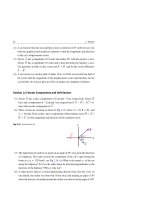
(4) A particle of mass m is moving horizontally with constant velocity v→ as shown
in Fig. 9.16. Find the magnitude and direction of the angular momentum of
→
the particle, Li , (i = 1, 2, . . . , 8), respectively about the eight points Oi , (i =
1, 2, . . . , 8).
Fig. 9.16 See Exercise (4)
O6
O7
d
O5
m
O8
O4
d
O1
d
O2
d
O3
290
9 Angular Momentum
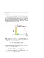
(5) A ball of mass m = 0.5 kg is moving horizontally with a speed v = 10 m/s at
the instant when its position is identified in Fig. 9.17. (a) What is the angular
momentum of the ball about O at this instant? (b) Neglecting air resistance,
find the rate of change of its angular momentum about O at this instant.
Fig. 9.17 See Exercise (5)
m
r
mg
6m
30
O
(6) By definition, kinetic energy K = 21 mv 2 , where m and v are the mass and speed
of a particle, respectively. Show that the kinetic energy of a particle moving
in a circular path is K = L 2 /2I, where L and I are, respectively, the angular
momentum and moment of inertia of the particle about the center of the circle.
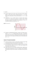
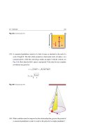
(7) A canonical pendulum consists of a bob of mass m attached to the end of a
cord of length . The bob whirls around in a horizontal circle of radius r at a
constant speed v while the cord always makes an angle θ with the vertical, see
Fig. 9.18. Show that the magnitude of the angular momentum of the bob about
its point of support O is given by:
L=
m2 g
3
sin θ tan θ
Fig. 9.18 See Exercise (7)
O
m
9.4 Exercises
291
(8) Two identical particles 1 and 2 have respective position vectors →
r 1 and →
r 2 with
respect to an arbitrary origin O. The two particles have equal and opposite
linear momenta →
p and −→
p as shown in Fig. 9.19. Show that the total angular momentum of this system is independent of the choice of the origin and
independent of where the traveling particles are located.
Fig. 9.19 See Exercise (8)
p
2
p
1
r2
r1
O
(9) Two particles of masses m1 = 2 kg and m2 = 3 kg are joined by a rod of mass
M = 0.5 kg and length d = 0.75 m. The assembly rotates freely in the xy-plane
about a pivot through the center of the rod, as shown in Fig. 9.20. Find the
angular momentum of the system when the speed of each particle is v = 6 m/s.
Fig. 9.20 See Exercise (9)
y
m1
M
x
O
d
m2
(10) Consider the seconds hand of a particular analog clock to be a thin rod of
length = 14 cm and mass m = 5 g, see Fig. 9.21. (a) If the seconds hand rotates
constantly, what is its angular speed? (b) Find the magnitude of the angular
momentum of the seconds hand about an axis perpendicular to the center of
the clock’s face.
292
9 Angular Momentum
Ho
urs
Fig. 9.21 See Exercise (10)
tes
s
nd
co
Se
Minu
m
(11) Three identical particles, each of mass m = 0.5 kg, are attached at equal distances from one end of a rod of length = 2 m and mass M = 3 kg, see Fig. 9.22.
The system is rotating with angular speed ω = 2 rad/s about an axis perpendicular to the rod through the free end at O. (a) What is the moment of inertia of
the system about O? (b) What is the angular momentum of the system about
O?
Fig. 9.22 See Exercise (11)
m
m
M
m
O
a
a
a
Pivot
(12) Each of two identical particles of mass m = 0.5 kg attached at one end of two
identical rods each of length a = 0.2 m and mass M = 0.3 kg. The other ends
of the two rods are mounted perpendicular to a lightweight axle such that
the distance between the rods is d = 0.6 m, see Fig. 9.23. The axle rotates at
ω = 4 rad/s. (a) What is the total angular momentum of the two particles about
the CM of the system? (b) What is the total angular momentum of the two rods
about the axle? (c) What angle does the total angular momentum of the whole
system make with the axle?
(13) Three identical thin rods, each of mass m and length R, are fastened together
to form the letter H. A circular hoop, of mass m and radius R, is fastened to the
rods to form the rigid structure shown in Fig. 9.24. The rigid structure rotates
9.4 Exercises
293
with a constant angular speed about a vertical axis with a period of rotation T .
(a) Find an expression for the structure’s moment of inertia and angular momentum about the axis of rotation. (b) Evaluate the two expressions of part (a) when
m = 0.5 kg, R = 0.1 m, and T = 2 s.
Fig. 9.23 See Exercise (12)
Axle
m
M
a
y
CM
d
x
M
m
a
Fig. 9.24 See Exercise (13)
Axle
z
R
R
R
m
m
m
m
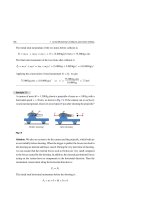
(14) A block of mass m1 located on a smooth horizontal surface is connected by a
light non-stretchable cord that passes over a pulley to a second block of mass
m2 , which hangs vertically, see Fig. 9.25. The pulley is a uniform cylinder of
mass M and radius R, and it rotates freely about its axle. (a) Find an expression
for the net external torque about the pulley’s axle. (b) Find an expression for
the net angular momentum about the pulley’s axle. (c) Find an expression for
the magnitude of the acceleration of the two blocks and its value if m1 = 6 kg,
m2 = 3 kg, M = 2 kg, R = 0.1 m, and g = 10 m/s2 .
(15) A disk has a moment of inertia I = 2 kg.m2 about its axis of symmetry. The
angular speed of the disk depends on the time t by ω = (12 rad/s3 ) t 2 . (a) Find
294
9 Angular Momentum
the angular acceleration α and the angular momentum L of the disk as a function
of time, and find their values at t = 2 s. (b) Show that using the expressions for
α and L leads to the same expression for the net torque on the disk as a function
of time, and find its value at t = 2 s.
Fig. 9.25 See Exercise (14)
M
m1
R
m2
(16) A uniform solid sphere of mass M = 10 kg and radius R = 10 cm turns counterclockwise with an angular speed ω = 5 rad/s about a vertical axis that touches
its surface, see Fig. 9.26. What is the magnitude and direction of its angular
momentum about this axis?
Fig. 9.26 See Exercise (16)
z
M
R
R
(17) A boy of mass m = 40 kg is standing on the rim of a merry-go-round that is
rotating with angular speed ω = 0.5 rev/s about an axis through its center. The
merry-go-round is a uniform disk of mass M = 120 kg and radius R = 3.5 m.
Find the total angular momentum of the boy-disk system by treating the boy
as a point.
(18) Two wheels of radii Ra and Rb are connected by a non-stretchable belt that
does not slip on their circumferences, see Fig. 9.27. The radius Ra is four times
9.4 Exercises
295
the radius Rb . Find the ratio of the moment of inertia Ia /Ib and mass Ma /Mb
if both wheels have: (a) the same angular momentum about their central axis,
and (b) the same rotational kinetic energy.
Fig. 9.27 See Exercise (18)
a
Ra
b
Rb
(19) If an impulsive force F(t) with moment arm R acts on a rigid body of moment
of inertia I for a short time t, then show that the angular speed of the body
will change from an initial value ωi to a final value ωf according to the angular
impulse formula:
JR =
τ dt = FR t = I(ωf − ωi )
where F is the average value of the force during the time it acts on the body.
[Hint: It is the rotational analogy of Eq. 7.9].
(20) A wheel of radius Ra and moment of inertia Ia is rotating about its central axle
with angular speed ωa . Another small wheel is stationary and has a radius Rb
and moment of inertia Ib about its central axle. The smaller wheel is moved
until it touches the larger wheel and rotates due to the friction between them,
as in the upper part of Fig. 9.28. After the initial slipping period is over, the
two wheels rotate at constant angular speeds ωa and ωb , see the lower part of
Fig. 9.28. By applying the angular impulse relationship of Exercise 19, find the
final angular speed ωb of the small wheel.
(21) A block of mass m1 located on a rough horizontal surface is connected by a
light non-stretchable cord that passes over a pulley to a second block of mass
m2 , which is allowed to move on a rough inclined plane of angle θ, as shown
in Fig. 9.29. The pulley is a uniform cylinder of mass M and radius R, and
rotates freely about its axle. The coefficients of kinetic friction for the two
blocks on the horizontal and inclined planes are μk1 = 0.35 and μk2 = 0.5,
respectively. (a) Draw free-body diagrams of the two blocks and the pulley.
(b) Find the acceleration of the two blocks and the tensions in the two sections
296
9 Angular Momentum
of the cord when m1 = 2 kg, m2 = 5 kg, M = 10 kg, R = 0.1 m, sin θ = 4/5,
cos θ = 3/5, and g = 10 m/s2 . (c) If the system starts from rest, find the angular
momentum of the pulley about its axis as a function of time.
Fig. 9.28 See Exercise (20)
Time t
F
a
0
b
Ra
Rb
Ib
Ia
F
Time t
t
F
a
b
Ra
Ib
Ia
Fig. 9.29 See Exercise (21)
F
a,
m1
Rb
M,R
a,
m2
(22) Determine the angular momentum of the Earth: (a) about its rotational axis
(assume that Earth is a uniform sphere of mass M = 6.0 × 1024 kg and radius
R = 6.4 × 10⁶ m), and (b) about the Sun (assume Earth to be a particle at
1.5 × 10¹¹ m from the Sun).
(23) Two blocks having masses m1 and m2 (m2 > m1 ) are connected to each other by
a light non-stretchable cord that passes over two identical pulleys; each pulley
is a uniform cylinder with a mass M and radius R, which rotates freely about its
axle, as shown in Fig. 9.30. Assume no slipping happens between the cord and
9.4 Exercises
297
the pulleys. (a) Find an expression for the net external torque of each pulley
about its axle; then find the total net external torque of the system. (b) Find an
expression for the net angular momentum of each pulley about its axle; and then
find the total net angular momentum of the system. (c) Apply τext = d L/d t
onto the whole system to find the acceleration of each block and the tensions
T1 , T2 , and T3 in the cord.
Fig. 9.30 See Exercise (23)
T3
M
R
a,
M
R
T2
T1
m1
m2
a,
Section 9.2 Conservation of Angular Momentum
(24) A person is rotating on a frictionless surface at a rate of 1.5 rev/s with his arms
at his sides. When he raises his arms to the horizontal position, the speed of
rotation decreases to a rate of 0.75 rev/s. What is the percentage increase in
moment of inertia of the person?
(25) A skater has a moment of inertia 4.5 kg.m2 when rotating on a frictionless
surface at a rate of 1 rev/s. What is her final moment of inertia if she increases
her spin to the maximum value of 2.5 rev/s? How can she accomplish this
change?
(26) A diver pushes a swimming pool board to jump into the air and acquires an
initial angular momentum about her center of mass. Then she curls her body
about her center of mass (by tucking in her arms and legs) to reduce her moment
of inertia by a factor of 3.25. If she is able to make 3 revolutions in 2.25 s while
she is in that tucked position, what was her initial angular speed?
(27) A uniform horizontal rod of mass M and length d rotates initially with angular
speed ωi about a vertical frictionless axle running through its center. Then two
stationary small balls of clay, each of mass m, are made to stick to each end of
the rod. What is the final angular speed of the system?
298
9 Angular Momentum
(28) A merry-go-round of radius R = 2.5 m and moment of inertia I = 300 kg.m2
is rotating at 10 rev/min. A boy of mass m = 40 kg jumps onto the merry-goround and manages to sit down quickly on its rim. What is the final angular
speed of the system?
(29) A merry-go-round of a mass M = 210 kg and radius R = 5.5 m is mounted on
a frictionless bearing. While a man of mass m = 90 kg is standing on its outer
edge, the system is rotating with an angular speed ωi = 0.2 rev/s. Then, slowly,
the man walks 3 m towards the center of the merry-go-round and stops. How
fast will the merry-go-round be rotating after he stops?
(30) Rather than walking inwards, suppose the man in Exercise 29 decided to jump
radially outwards relative to the merry-go-round. What will be the angular
speed of the merry-go-round?
(31) A boy of mass m = 30 kg stands on the edge of a stationary small merry-goround of moment of inertia Im = 150 kg.m2 and radius R = 2 m. The merry-goround can rotate freely without friction about its axis. The boy jumps off the
merry-go-round in a tangential direction with a linear speed v = 2 m/s. What
is the angular speed of the merry-go-round after the boy leaves it?
(32) A person of mass m = 80 kg (treated as a point) stands at the center of a freely
rotating cylindrical platform of a mass M = 120 kg and radius R = 4 m. The
platform is mounted on a frictionless bearing and rotates with an angular speed
ωi = 1.5 rad/s. The person walks radially and slowly to the edge of the platform
and stops. (a) What is the final angular speed of the system? (b) Find the initial
and final total rotational energy of the system.
(33) A uniform disk of radius R and a uniform rod of length 2R have the same mass
M. The disk is rotating freely without friction about its axle with angular speed
ωi = 3 rev/s while the rod is at rest and has its center coinciding with the disk’s
axle, see Fig. 9.31. The rod is dropped onto the disk and sticks to it such that
their centers coincide (i.e. the collision is completely inelastic). What is the
final angular speed of the system?
(34) Two disks have a common frictionless axle and moments of inertia I1 = 5 kg.m2
and I2 = 10 kg.m2 . Initially, disk I1 is rotating with an angular speed ωi = 6 rev/s
about the axle, while disk I2 is not rotating. Disk I2 then drops onto disk I1 , see
Fig. 9.32. Due to the friction between their surfaces, the two disks eventually
reach the same angular speed ωf . (a) Find the final angular frequency ωf . (b)
Find the percentage decrease in the rotational kinetic energy.
9.4 Exercises
Fig. 9.31 See Exercise (33)
299
2R
R
R
M
M
f
i
Fig. 9.32 See Exercise (34)
I2
f
i
I1
I1
I2
(35) An asteroid of mass m = 106 kg is traveling at a speed of v = 4 × 10⁴ m/s relative to the Earth. The asteroid hits the Earth tangentially at the equator in the
direction opposite to its rotation and gets embedded at its surface, see Fig. 9.33.
Assume that Earth is a uniform sphere of mass M = 6.0 × 1024 kg and radius
R = 6.4 × 10⁶ m. Since no net external forces acting on this system can produce
a torque about the axis of the Earth (all forces and torques are internal), then
the angular momentum of the system is conserved about the axis of the Earth.
As a result of this collision, find the percentage change in the Earth’s angular
speed.
Fig. 9.33 See Exercise (35)
Northpole
Ea
rth
M
R
m
Equa
tor
P
Asteroid
300
9 Angular Momentum
(36) Suppose the asteroid in Exercise 35 hits the equator circle with an incident angle
θ = 45◦ , see Fig. 9.34. By what factor does this completely inelastic collision
affect the angular speed of the Earth?
Fig. 9.34 See Exercise (36)
Equator circle
R
m
P
45
(37) A thin vertical rod of mass M and length d can rotate about a frictionless pivot at
its upper end, see Fig. 9.35. A small clay ball of mass m traveling horizontally
with a speed v hits the rod at its center and sticks to it. (a) Find the angular
speed of the system just after the collision. (b) How high does the lower end
rise?
Pivot O
M
m
M
M d
CM
Just before
collision
CM
m
f
Just after
collision
m
h
H
2h
At maximum
height
Fig. 9.35 See Exercise (37)
(38) A stationary thin horizontal rod of mass M and length d can rotate about a
frictionless vertical axle through its center at O, see Fig. 9.36. A small clay ball
of mass m traveling horizontally with a speed v hits the rod at one of its ends
and sticks to it. (a) Find the angular speed of the system just after the collision.
(b) What is the fractional loss in mechanical energy due to the collision?
(39) A stationary horizontal wooden stick of length d = 75 cm and mass M = 0.4 kg
can rotate about a frictionless vertical axle through its center at O, see Fig. 9.37.
9.4 Exercises
301
A bullet of mass m = 5 × 10⁻³ kg and horizontal speed vi = 200 m/s is shot into
the stick midway between the axle and one end. The bullet penetrates the stick
in a very short time and leaves with a speed vf = 100 m/s. (a) Find the angular
speed of the stick after the collision. (b) Find the percentage decrease in total
energy.
Fig. 9.36 See Exercise (38)
Top view
m
m
f
Axle O
M
d
M
O
CM
Just after
collision
Just before
collision
Fig. 9.37 See Exercise (39)
Top view
m
m
i
O
M
Vertical
axle
Just before
collision
d
O
f
M
f
Just after
collision
(40) A stationary thin rod of mass M and length d rests on a frictional table.
A small clay ball of mass m traveling horizontally with a speed v hits the
rod perpendicularly at a point d/4 from its center and sticks to it, see Fig. 9.38.
Determine the translational and rotational motion of the rod after the collision.
(41) A student stands at the center of a turntable with his arms outstretched. In
each hand, he holds a 10 kg-dumbbell at 1 m from the axis of the turntable.
The turntable is rotating about a vertical frictionless axle with angular speed
ωi = 0.5 rev/s. (a) Find his final angular speed if he pulls each dumbbell to
302
9 Angular Momentum
his stomach at 0.2 m from the axis of the turntable. The moment of inertia of
the student with his arms outstretched is 4 kg.m2 , but it is 3.2 kg.m2 with his
hands at his stomach. (b) Find the initial and final kinetic energy of the system.
Explain the meaning if they are different.
Fig. 9.38 See Exercise (40)
m
d/4
CM
M
d
Section 9.3 The Spinning Top and Gyroscope
(42) To form a top, a uniform disk of mass M = 50 g and radius R = 2 cm is rigidly
attached to an axial rod of negligible mass. The top spins on a frictionless
surface about its axis of symmetry with angular speed ω = 6,000 rev/min. How
much work was done to get the top to spin at that rate?
(43) The center of the disk in exercise 42 is at r = 3 cm from the tip of the top at the
surface of contact to the disk. What is the angular speed of precession of the
top about the vertical axis?
(44) To form a toy gyroscope, a disk of mass M = 150 g and radius R = 6 cm
is mounted at the center of a thin axle of 20 cm length. The disk spins at
ω = 50 rev/s when one end of the axle rests on a stand and the other end precesses horizontally. What is the angular speed of precession of the top about
the vertical axis?
(45) A top of mass M = 200 g spins about its axis of symmetry with angular speed
ω = 18 rev/s and makes an angle θ = 25◦ with the vertical. It experiences precession at a rate of 1 rev every 5 s. The center of mass of the top is 4 cm from
its tip. (a) What is the moment of inertia of the top? (b) Find the torque on the
top.
10
Mechanical Properties of Matter
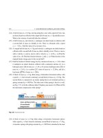
The physical states of matter can generally be divided into three broad classes: solids,
liquids, and gases, see Fig. 10.1. A solid maintains its shape: it resists the action of
external forces that tend to change its shape or volume. Liquids and gases are fluids.
A fluid can easily change shape, and flows when subjected to a force. The three states
of matter are distinguishable at the microscopic level as follows:
Solid
Maintans its Shape
Fixed Volume
Liquid
Shape of the Container
Fixed Volume
Gas
Shape of the Container
Volume of the Container
Fig. 10.1 The three states of matter: solid, liquid, and gas
1. A solid is a highly ordered array of atoms or molecules that are bound securely
by mutual electrical forces.
2. A liquid is a crowded assembly of mobile atoms or molecules. Each atom or
molecule is in contact with several neighbors, but is not bound securely to any of
them. As an atom or molecule moves about in a liquid, it collides frequently with
its neighbors.
H. A. Radi and J. O. Rasmussen, Principles of Physics,
Undergraduate Lecture Notes in Physics, DOI: 10.1007/978-3-642-23026-4_10,
© Springer-Verlag Berlin Heidelberg 2013
303
304
10 Mechanical Properties of Matter
3. A gas consists of atoms or molecules that are far apart and consequently move
independently, with no forces keeping them together or pushing them apart. Collisions of atoms or molecules in gases are infrequent in comparison to those in
liquids.
10.1
Density and Relative Density
The density (or mass density) of a material is defined as the mass per unit volume. If
a mass m is distributed uniformly over a volume V, the density will be given by the
following equation:
ρ=
m
V
(10.1)
The SI unit of density is kg/m3 . If the mass is not uniformly distributed, then
Eq. 10.1 defines the average density. The densities of several materials are listed in
Table 10.1.
Table 10.1 Density and relative density comparison (approximates)
Material type
Material name
Density (kg/m3 )
Relative density
Gas
Helium
0.179
1.79 × 10⁻⁴
Air
1.29
1.29 × 10⁻³
Carbon dioxide
1.98
1.98 × 10⁻³
Alcohol
7.9 × 10²
0.79
Gasoline
8.6 × 10²
0.86
Water
1 × 10³
1
Mercury
13.6 × 10³
13.6
Glass (common)
2.4 − 2.8 × 10³
2.5
Aluminum
2.7 × 10³
2.7
Iron
7.86 × 10³
7.86
Copper
8.92 × 10³
8.92
Silver
10.5 × 10³
10.5
Lead
11.36 × 10³
11.36
Uranium
19.07 × 10³
19.07
Gold
19.3 × 10³
19.3
Liquid
Solid
10.1 Density and Relative Density
305
The relative density of a substance tells us how many times more dense the substance is than pure water, see Table 10.1. Sometimes we refer to it as the specific
gravity (SG). Thus:
SG =
ρ
ρwater
(10.2)
Example 10.1
Calculate the average density of both the Earth and the Sun, given that the
mass and radius of the Earth are mE = 5.98 × 1024 kg and RE = 6.37 × 10⁶ m,
respectively, and the mass and radius of the Sun are mS = 1.99 × 1030 kg and
RS = 6.95 × 10⁸ m, respectively. Compare between the resulting average densities.
Solution: Matter in the Earth and the Sun is not uniform. In spite of this fact,
we can use Eq. 10.1 to calculate their average density. Using the given radius, we
calculate the volume of the Earth to be:
VE = 43 π RE3 = 1.08 × 10²¹ m3
Thus, the average density of the Earth is:
ρE =
mE
5.98 × 1024 kg
=
= 5.54 × 10³ kg/m3
VE
1.08 × 10²¹ m3
In comparison to water, the average density of the Earth is 5.54 times more dense
than water.
Similarly, we use the given radius of the Sun to calculate its volume:
VS = 43 π RS3 = 1.41 × 1027 m3
Thus, the average density of the Sun is:
ρS =
mS
1.99 × 1030 kg
=
= 1.41 × 10³ kg/m3
VS
1.41 × 1027 m3
In comparison to water, the average density of the Sun is 1.41 times more dense
than water. Although the mass and volume of the Earth are much smaller than the
mass and volume of the Sun, the average density of the Earth is nearly four times
the average density of the Sun. That is:
ρE
4ρS
306
10.2
10 Mechanical Properties of Matter
Elastic Properties of Solids
All solids are to some extent elastic. This means that we can change their dimensions
slightly by pulling, pushing, twisting, and/or compressing them. We shall discuss the
elastic properties of solids by introducing the concepts of stress and strain.
Stress:
Stress is the magnitude of the applied external force that acts perpendicularly
on a unit area of the object.
Strain:
Strain is a measure of the degree of deformation of the object.
It is found that for small stresses, stress is proportional to strain. The proportionality constant is called the elastic modulus and it depends on the material being
deformed, as well as on the nature of the deformation. Therefore:
Elastic modulus =
Stress
Strain
(10.3)
This relation is equivalent to Hooke’s law that states: Stress ∝ Strain. In this chapter,
we introduce the three most famous types of deformations and their elastic moduli:
Young’s Modulus:
Measures the resistance of a solid to a change in its length.
Shear Modulus:
Measures the resistance to motion of the planes of solids when sliding over
each other.
Bulk Modulus:
Measures the resistance of a solid (or a liquid) to a change in its volume.
10.2 Elastic Properties of Solids
307
10.2.1 Young’s Modulus: Elasticity in Length
Young’s Modulus measures the resistance of a solid to a change in its length, which
indicates its stiffness. Consider a metallic long rod of original length L and crosssectional area A. When an external force F⊥ is applied perpendicularly to the crosssectional area A of a rod, its internal forces resist its distortion. As a final result,
the rod attains equilibrium when its length increases to a new length L + L and
the magnitude of the perpendicular external force F⊥ exactly balances the internal
forces, see Fig. 10.2a. In light of this, we define the tensile stress and the tensile
strain as follows:
Tensile stress =
Tensile strain =
F⊥
A
(N/m2 )
(10.4)
L
L
(10.5)
The relation between the tensile stress and the tensile strain is linear when the rod is
in its elastic range. When the stress exceeds what is called the elastic limit, the rod
is permanently distorted and will not return to its original shape after the stress is
removed. As the stress is increased even further, the rod will ultimately break, see
Fig. 10.2b.
F
Stress
Breaking
point
Elasti climit
A
L
L
L
Range of
permanent
deformation
Elastic
behaviour
Strain
F
(a)
(b)
Fig. 10.2 (a) A rod of height L and cross-sectional area A. The rod stretches by an amount
application of a tensile stress. (b) The stress versus strain curve for an elastic solid
L after
308
10 Mechanical Properties of Matter
We use Eqs. 10.4 and 10.5 to define Young’s modulus, Y, as:
Y=
Tensile stress
F⊥ /A
=
Tensile strain
L/L
(N/m2 )
(10.6)
This quantity is used to characterize a solid that is stressed under either tension or
compression. Table 10.2 depicts some values for Y.
Table 10.2 Young’s modulus for different materials (approximates)
Young’s modulus Y × (109 N/m2 )
Material name
Rubber
0.004
Lead
16
Glass
65 – 78
Aluminum
70
Brass
91
Copper
110
Steel
200
Tungsten
350
Example 10.2
A pendulum consists of a big sphere of mass m = 30 kg hung from the end of a
steel wire that has a length L = 15 m, a cross-sectional area A = 9 × 10⁻⁶ m2 , and
Young’s modulus Y = 200 × 109 N/m2 . Find the tensile stress on the wire and the
increase in its length.
Solution: The applied force on the wire must equal to the weight of the sphere,
i.e. F⊥ = m g. Thus, the tensile stress will be:
Tensile stress =
mg
(30 kg) × (9.8 m/s2 )
F⊥
=
=
= 3.27 × 10⁷ N/m2
A
A
9 × 10⁻⁶ m2
Using the value of the Young’s modulus Y = 20 × 1010 N/m2 and the length of
the steel wire before stretching L = 15 m, we get:
Y=
F⊥ /A
L/L
⇒
L=
F⊥ /A
3.27 × 10⁷ N/m2
L=
× 15 m = 2.45 × 10⁻³ m
Y
200 × 109 N/m2
Note that this large stress produces a relatively small change in L.
10.2 Elastic Properties of Solids
309
When we carefully study the deformation of the rod, we find that the rod’s length
L increases by L in the direction of the force while it radius r decreases by | r|,
where r is negative, in a direction perpendicular to the force, see Fig. 10.3. The
tensile strain L/L of the rod is called the linear strain. The strain − r/r is called
the lateral strain, and Poisson’s ratio μ is defined as:
μ=
r/r
L
Lateral strain
=−
=−
Linear strain
L/L
r
r
L
⇒
μ=−
L dr
r dL
(10.7)
The minus sign is inserted in this definition to make μ positive.
A
r
r - |Δr|
F⊥
F⊥
L
39.58
After
Before
Fig. 10.3 The length of the rod will increase by
L + ΔL
L and its radius will decrease by
r (exaggerated
scale) after applying a tensile stress F⊥ /A
Example 10.3
A cylindrical steel rod has a length of 2 m and a radius of 0.5 cm. A force of
magnitude 2 × 10⁴ N is acting normally on each of its ends. Find the change in its
length and radius, if the Young’s modulus Y is 200 × 109 N/m2 and the Poisson’s
ratio μ is 0.25.
Solution: Using F⊥ = 2 × 10⁴ N, A = π r 2 = π × (0.5 × 10⁻² m)2 = 7.9 × 10⁻⁵
m2 , L = 2 m, and Y = 200 × 109 N/m2 in Eq. 10.6, we have:
L=
F⊥ L
(2 × 10⁴ N)(2 m)
=
= 2.5 × 10⁻³ m = 0.25 cm
YA
(200 × 109 N/m2 )(7.9 × 10⁻⁵ )
From the definition of the Poisson’s ratio μ, we have:
r=−
Note that
μr L
0.25 × (0.5 × 10−2 m)(2.5 × 10⁻³ m)
=−
= −1.56 × 10⁻⁶ m
L
(2 m)
L ≈ 1,600 | r|, i.e. | r| is extremely small compared to
L.
310
10 Mechanical Properties of Matter
10.2.2 Shear Modulus: Elasticity of Shape
Another type of deformation occurs when a solid is subject to a force applied parallel
to one of its surfaces while the opposite surface is kept fixed. Figure 10.4 shows a
cylindrical rod subjected to a linear or torsional shear stress deforming it by an amount
x due to a force F parallel to the surface area A. As a final result, the shape of
the rod will attain equilibrium when the effect of the shear force F balances exactly
the internal shear forces. For linear shearing, we define the shearing stress and the
shearing strain as follows:
Shearing stress =
F
Tangential acting force
=
Area of surface being sheared
A
Shearing strain =
x
Distance sheared
=
= tan θ
Distance between surfaces
h
A
x
F
(N/m2 )
(10.8)
θ
(10.9)
Top view
F
F
h
x
F
Fixed end
Linear shearing
Torsional shearing
Fig. 10.4 The left part shows a cylindrical rod of height h. The middle part shows a linear shear where
the rod is subject to a shearing force F parallel to each of its surface areas. The rod is deformed through
an angle θ which is defined as the shearing strain. The right part shows a torsional shear when one end of
the rod is kept fixed
The approximation tan θ θ is valid for small strains. We use Eqs. 10.8 and 10.9 to
define the shear modulus, S, as follows:
S=
F /A
Shearing stress
=
Shearing strain
x/h
(N/m2 )
(10.10)
S is also called the modulus of rigidity or the torsion modulus and is significant only
for solids. Table 10.3 depicts some values for S.
10.2 Elastic Properties of Solids
311
Table 10.3 Shear modulus for different materials (approximates)
Material name
Shear modulus S × (109 N/m2 )
Rubber
0.001
Lead
6
Glass
23
Aluminum
23
Brass
36
Copper
42
Steel
80
Tungsten
120
Example 10.4
Assume that the rod in Fig. 10.4 has a cross-sectional area A = 2 × 10⁻³ m2 ,
length h = 1 m, and is made of brass with a shear modulus S = 36 × 109 N/m2 .
How large should the shear force F exerted on each edge of the rod be if the
displacement
x is 0.02 cm?
Solution: The shearing stress on each edge is:
Shearing stress =
F
F
=
= 500 F m−2
A
2 × 10⁻³ m2
The shearing strain is:
Shearing strain =
2 × 10⁻⁴ m
x
=
= 2 × 10⁻⁴
h
1m
From the definition of the shearing modulus Eq. 10.10 and the last two results,
we have:
S=
500F m−2
Shearing stress
=
Shearing strain
2 × 10⁻⁴
Using the given shear modulus value for brass, we get:
36 × 109 N/m2 =
500F m−2
2 × 10⁻⁴
Thus: F = (36 × 109 N/m2 )(2 × 10⁻⁴ )/(500 m−2 ) = 14,400 N = 1.44 × 10⁴ N