Hafez a radi, john o rasmussen auth principles of physics for scientists and engineers 14
Bạn đang xem bản rút gọn của tài liệu. Xem và tải ngay bản đầy đủ của tài liệu tại đây (366.49 KB, 20 trang )
10.4 Fluid Statics
317
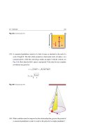
Fig. 10.7 The pressure P at a
Pa
depth h below the surface of a
liquid open to the atmosphere
is given by P = Pa + ρgh
h
P
dA
This relation verifies that the pressure is the same at all points having the same
depth from a liquid surface. Moreover, the pressure is not affected by the shape of
the container, see Fig. 10.8.
Fig. 10.8 The pressure in the
liquid is the same at all points
having the same depth. The
shape of the vessel does not
affect the pressure
Example 10.6
Find the pressure at depths of 10 m and 10 km in ocean water. Assume Pa ≡
1 atm
105 Pa, ρ
103 kg/m3 , and g
10 m/s2 .
Solution: The pressure at a depth h = 10 m will be:
P = Pa + ρgh = 105 Pa + (103 kg/m3 )(10 m/s2 )(10 m)
= 2 × 10⁵ Pa = 2 atm
The pressure at a depth h = 10 km = 104 m will be:
P = Pa + ρgh = 105 Pa + (103 kg/m3 )(10 m/s2 )(104 m)
= 1,001 × 105 Pa
1,000 atm
318
10 Mechanical Properties of Matter
The fact that the pressure in a fluid depends only on depth indicates that any
increase in pressure at the liquid surface must be transmitted to every point in the
liquid. This fact is known as Pascal’s law or Pascal’s principle.
An important application of Pascal’s law is the hydraulic lever illustrated in
Fig. 10.9. Let an external input force of magnitude F1 be exerted downwards on
a small piston of area A1 . The pressure will be transmitted through an incompressible fluid which then exerts an output force F2 on a larger piston of area A2 , balancing
the load.
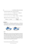
Fig. 10.9 A hydraulic device
used to magnify a force.
Load
Input
However, for small strokes
Output
F1
(small d1 ), the input and
output work done is the same
A1
.
d1
A2
5 .1 0
d2
F2
The pressure on both leveled pistons is the same. That is:
P=
F1
F2
=
A1
A2
⇒
F2 = F1
A2
A1
(Leveled pistons)
(10.21)
Thus, the force F2 is larger than F1 by the multiplying factor A2 /A1 . Hydraulic
brakes, car lifts, etc make use of this principle.
When we move the input piston downwards a distance d1 , the output piston moves
upwards a distance d2 , such that the same volume V of the incompressible liquid is
displaced at both pistons. Then, we get:
V = A1 d1 = A2 d2
⇒
d2 = d1
A1
A2
(10.22)
Thus, for A2 > A1 , the output piston moves a smaller distance than the input piston.
On the other hand, for small values of d1 , we can use Eq. 6.1 to find the following
input/output relationship:
W2 = F2 d2 = F1
A2
A1
d1
A1
A2
= F1 d1 = W1 (for small d1 only)
(10.23)
10.4 Fluid Statics
319
which shows that the work W1 done on the input piston by the applied force equals
the work W2 done by the output piston in lifting the load.
Measuring Pressures
The Mercury Barometer
Figure 10.10 shows a very basic mercury barometer used to measure atmospheric
pressure. Here, a long glass tube is first filled with mercury and then inverted with
its open end in a container filled with mercury.
Fig. 10.10 A closed-end
P=0
mercury barometer
h Pa
Pa
The closed end of the tube is nearly in a state of vacuum, i.e. with P 0. Moreover,
the pressure is the same at all points having the same horizontal level in mercury.
Therefore, according to Figure 10.10, the atmospheric pressure Pa will be given by:
Pa = ρgh, where ρ is the density of mercury and h is the height of the mercury
column.
The height of the mercury column is measured only if the barometer is set at a
place where g = 9.80665 m/s2 and the temperature of the mercury is 0◦ C. At this
temperature, the mercury has a density ρ = 13.595 × 10³ kg/m3 and the height of
mercury is measured to be exactly 760 mm. Therefore:
Pa = ρgh
= (13.595 × 10³ kg/m3 )(9.80665 m/s2 )(0.76 m)
= 1.013 × 10 Pa
5
(10.24)
320
10 Mechanical Properties of Matter
The Open-Tube Manometer
Figure 10.11 shows a very basic open-tube manometer used to measure the gauge
pressure of a gas. It consists of a U-tube containing a liquid, with one end of the tube
connected to a gas tank of pressure P, and the other end open to the atmosphere.
Fig. 10.11 An open-tube
Pa
manometer for measuring gas
pressure
Liquid
P
Gas tank
h
A
B
From this figure, we see that the pressure at point A is the unknown pressure P
of the gas in the tank. On the other hand, the pressure PA at point A is equal to the
pressure PB at point B, which equals Pa + ρgh, where ρ is the density of the liquid
and h is the height of the liquid column. Since PA = PB , we have:
P = Pa + ρgh
(10.25)
This relation gives us what we call the absolute pressure P. In general, the difference between an absolute pressure and an atmospheric pressure is called the gauge
pressure Pg . That is:
Pg = P − Pa = ρgh
(10.26)
The gauge pressure can be positive or negative, depending on whether P > Pa or
P < Pa . In inflated tires or in the human circulatory system, the absolute pressure is
greater than the atmospheric pressure (i.e. P > Pa ), so the gauge pressure is positive
(i.e. Pg > 0).
10.4 Fluid Statics
321
Example 10.7
The U shaped tube shown in Fig. 10.12 contains oil in the right arm and water in
the left arm. In static equilibrium, the measurements give h = 18 cm and d = 2 cm.
Fig. 10.12
d
h
B
Oil
Interface
What is the value of the density of the oil ρo ?
A
Water
Solution: The pressure PA at the oil–water interface of the right arm must be
equal to the pressure PB in the left arm at the same level. In the right arm, we use
Eq. 10.20 to get:
PA = Pa + ρo g(h + d)
In the left arm, we use the same Eq. 10.20 to get:
PB = Pa + ρw gh
Since PA = PB , we equate the last two equations to get:
ρo =
h
18 cm
ρw =
103 kg/m3 = 900 kg/m3
h+d
18 cm + 2 cm
Note that the answer does not depend on the atmospheric pressure.
Example 10.8
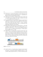
For the car lift shown in the Fig. 10.13, the pistons on the left and right have areas
25 cm2 and 750 cm2 respectively. The car and the right piston have a total weight
of 15,000 N. What force must be applied on the left piston (if it has negligible
weight)? What pressure will produce this force?
Solution: From Eq. 10.21, we have:
F1 = F2
A1
25 cm2
= (15,000 N)
= 500 N
A2
750 cm2
322
10 Mechanical Properties of Matter
Fig. 10.13
Load
F1
A1
A2
F2
The pressure that produce this force is given by:
P=
F1
500 N
=
= 2 × 10⁵ Pa
A1
25 × 10−4 m2
2 atm
∗ Example 10.9
(a) A person dives to a depth h = 50 cm below the water surface without inhaling
first. Find the pressure on his body and on his lungs. (b) Repeat part (a) when he
dives to a depth h = 5 m. When the diver ignores diving rules and foolishly uses
a snorkel tube at that depth, find the pressure on his lungs? Why he is in danger?
Assume that Pa = 1.01 × 10⁵ Pa, ρ = 103 kg/m3 , and g = 9.8 m/s2 .
Solution: (a) The external pressure on the diver’s body will be:
PBody = Pa + ρgh
= 1.01 × 10⁵ Pa + (103 kg/m3 )(9.8 m/s2 )(0.5 m)
= 1.01 × 10⁵ Pa + 4,900 Pa = 1.059 × 10⁵ Pa
1.05 atm
The diver’s body adjusts to that pressure by a very slight contraction until the internal pressure is in equilibrium with the external pressure. Consequently, his average
blood pressure increases, and the average air pressure in his lungs increases until
it balances the external pressure. Thus, his lung pressure will be at:
PLungs
1.05 atm
(b) When h = 5 m, the external pressure on the diver’s body will be:
PBody = Pa + ρgh
= 1.01 × 10⁵ Pa + (103 kg/m3 )(9.8 m/s2 )(5 m)
= 1.01 × 10⁵ Pa + 49,000 Pa = 1.5 × 10⁵ Pa
1.5 atm
10.4 Fluid Statics
323
Again, as in part (a), the pressure inside his lungs will be:
PLungs
1.5 atm
If the diver foolishly uses a 5 m snorkel tube, the pressurized air in his lungs will
be expelled upwards through the tube to the atmosphere. Consequently, the air
pressure in his lungs will drop rapidly from 1.5 to 1 atm. This 0.5 atm pressure
difference is sufficient to collapse his lungs and force his still-pressurized blood
into them.
Buoyant Forces and Archimedes’ Principle
In a swimming pool, you may have noticed that it is relatively easy to carry an object
that is totally or partially immersed in the water. This is because you must support
only part of the object’s weight, while the buoyant force supports the remainder.
This important property of fluids in hydrostatic equilibrium is summarized by
Archimedes’ principle, which can be stated as follows:
Archimedes’ Principle:
A body fully or partially immersed in a fluid is buoyed up by a force equal to
the weight of the fluid displaced by the body.
Let us show that the buoyant force is equal in magnitude to the weight of the
displaced fluid. We can do this by considering a cube of fluid of height h (and hence
volume Vf = h3 ) as in Fig. 10.14a.
The same as
the fluid,
but colored
differently
FB
F B =W f
Object
h
Wf
(a)
h
Fluid
Wo
(b)
Fig. 10.14 (a) External forces acting on a cube of fluid (colored blue). Under equilibrium, the fluid’s
weight Wf is equal to the buoyant force FB . (b) A cube of weight Wo is buoyed by a force FB = Wf
324
10 Mechanical Properties of Matter
The cube of this fluid is in equilibrium under the action of the forces on it. One
→
of the forces is its own weight Wf . Apparently, the rest of the fluid in the container is
buoying up the cube and holding it in equilibrium. Therefore, the magnitude of this
buoyant force, FB , must be exactly equal in magnitude to the weight of the fluid.
That is:
FB = Wf
(10.27)
Now, imagine we replace the cube of fluid by a cubical object of the same dimensions. The fluid surrounding the cube will behave the same way, regardless whether
the cube is a fluid or a solid. Therefore, the buoyant force acting on an object of any
density will be equal to the weight of the fluid displaced by the object, i.e. FB = Wf .
To show this result explicitly, we notice in Fig. 10.14b that the pressure at the
bottom of the object is greater than the pressure at the top by P = ρf gh, where ρf
is the density of the fluid. Since the pressure difference P equals the buoyant force
per unit area, then P = FB /A, where A = h2 is the area of one of the cube’s faces.
Therefore:
FB =
P A = ρf gh A = ρf Vf g = Wf
(10.28)
Consider the object of Fig. 10.14b to be of weight Wo = ρo Vo g, where ρo and Vo
are its density and volume, respectively. If the object is totally immersed in a fluid
of density ρf , the buoyant force will be FB = Wf = ρf Vf g, where Vf = Vo . Thus, the
net force on the object will depend only on ρo and ρf , see parts of Fig. 10.15a–c.
FB
FB
At rest
a
W
W
(b)
a
W
Floating
W
f
f
(a)
Motion
Motion
FB
FB
f
(c)
f
(d)
Fig. 10.15 An immersed object of density ρo when: (a) ρo > ρf , (b) ρo = ρf , (c) ρo < ρf , and (d) A
floating object where ρo Vo = ρf Vf
Now, if that object floats; see Fig. 10.15d, the upward buoyant force will be
FB = Wf = ρf Vf g, where Vf is the volume of the displaced fluid and Vf = Vo .
10.4 Fluid Statics
325
Equilibrium in this case gives:
ρo Vo = ρf Vf
(10.29)
Example 10.10
A piece of steel has a mass ms = 0.5 kg and a density ρs = 7.8 × 10³ kg/m3 . The
steel is suspended in air by a string attached to a scale, see Fig. 10.16. After that,
the steel is immersed in a container filled with water of density ρw = 103 kg/m3 .
Find the tension in the string before and after the steel is immersed.
Fig. 10.16
Water
TA
Ws
TW
FB
w
Ws
Solution: When the piece of steel is suspended in air, the tension in the string Ta
equals the weight ms g of that piece of steel. That is:
Ta = ms g = (0.5 kg)(9.8 m/s2 ) = 4.9 N
When the steel is immersed in water, it experiences an upward buoyant force FB .
Thus, the tension in the string will be reduced to a new value Tw , see the figure.
Equilibrium in this case gives:
Tw + FB = ms g
⇒
Tw = ms g − FB
⇒
Tw = 4.9 N − FB
326
10 Mechanical Properties of Matter
To find FB , we first calculate the volume of the steel as follows:
Vs =
ms
0.5 kg
=
= 6.4 × 10⁻⁵ m3
ρs
7.8 × 10³ kg/m3
This volume equals the volume of the displaced water. That is:
Vw = 6.4 × 10⁻⁵ m3
Since the buoyant force equals the weight of the displaced water, then:
FB = mw g = ρw Vw g = (103 kg/m3 )(6.4 × 10⁻⁵ m3 )(9.8 m/s2 ) = 0.63 N
Therefore, the tension in the string Tw (the apparent weight) will be:
Tw = 4.9 N − FB = 4.9 N − 0.63 N = 4.3 N
Example 10.11
The approximate density of ice is ρi = 918 kg/m3 and the approximate density of
sea water in which an iceberg floats is ρw = 1,020 kg/m3 , see Fig. 10.17. What
fraction of the iceberg is beneath the water surface?
Fig. 10.17
FB
Wi
Solution: The iceberg floats, as shown in the figure, due to the effect of an upward
buoyant force given by:
FB = Ww = ρw Vw g
where Vw is the volume of the displaced water or the volume of the iceberg beneath
the water surface. The weight of the iceberg is:
10.4 Fluid Statics
327
Wi = ρi Vi g
where Vi is the volume of the iceberg. Equilibrium in this case gives FB = Wi .
That is:
Vw
ρi
918 kg/m3
=
=
= 0.90 or 90%
Vi
ρw
1,020 kg/m3
Thus, 90% of the iceberg lies below water level. This means that, only 10% of
an iceberg—its tip is above the surface of the water.
Example 10.12
An object of a known density ρo floats three-fourths immersed in a liquid of
unknown density ρf . Find the density of the liquid.
Solution: We use Eq. 10.29 when Vf = 43 Vo . Then:
ρf = ρo
Vo
Vo
= ρo 3
= 43 ρo
Vf
V
4 o
Note that ρf is larger than ρo by the reciprocal of the immersed ratio.
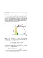
Example 10.13
A helium-filled balloon has a volume Vb = 8 × 10³ m3 and balloon mass mb =
200 kg, see Fig. 10.18. What is the maximum mass m of a load that keeps the balloon in equilibrium? Neglect the air displaced by the load. Take ρHe = 0.18 kg/m3
to be the density of helium and ρair = 1.28 kg/m3 to be the density of air.
Fig. 10.18
FB
(m He +m b +m )g
m
Solution: The volume of the displaced air equals the balloon’s volume, i.e.
Vair = Vb . According to Archimedes’ principle, the buoyant force is the weight of
328
10 Mechanical Properties of Matter
the displaced air, i.e.:
FB = Wair = ρair Vair g = ρair Vb g
Since the balloon’s volume is approximately equal to the volume of helium, i.e.
VHe
Vb , then the weight of the helium is:
WHe = ρHe VHe g = ρHe Vb g
At equilibrium, see Fig. 10.18, we have:
FB = WHe + Wb + mg
Thus:
⇒
ρair Vb g = ρHe Vb g + mb g + m g
m = (ρair − ρHe )Vb − mb
= (1.28 kg/m3 − 0.18 kg/m3 )(8 × 10³ m3 ) − 200 kg = 8,600 kg
10.5
Fluid Dynamics
Ideal Fluids
The motion of a real fluid is very complicated. Instead, we shall discuss the motion
of an ideal fluid that will obey the following four assumptions:
1. Steady flow: The velocity of the fluid at any specific point does not change with
time. However, in general the velocity might vary from one point to another.
2. Incompressible flow: The density of the fluid does not change with time. That is,
the density has a constant uniform value.
3. Non-viscous flow: A tiny object can move through the fluid without experiencing
a viscous drag force; that is, there is no resistive force due to viscosity.
4. Irrotational flow: A tiny object can move through the fluid without rotating about
an axis passing through its center of mass.
Streamlines
A streamline is the path traced out by a tiny fluid element, called a fluid “particle”.
As the fluid particle moves, its velocity may change in magnitude or in direction or
both. However, the velocity of the fluid particle at any point is always tangent to the
streamline at that point, see Fig. 10.19a. Streamlines never cross each other because
10.5 Fluid Dynamics
329
if they do, a fluid particle could move either way at the cross over point, and the flow
would not be steady.
When air flows around objects, the air particles must avoid the object, see Fig.
10.19b. Conservation of mass sets up the streamlines that the air particles must follow
to avoid the object.
Air flow
P
(a)
(b)
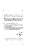
Fig. 10.19 (a) The diagram shows a set of streamlines. A fluid particle P traces out a streamline as
it moves. The velocity vector of the fluid particle is tangent to the streamline at every point. (b) The
streamlines of air flow near two different obstacles
Equation of Continuity
In flows like that of Fig. 10.19b, we consider a fluid flowing through a tube called
a stream tube, or tube of flow, whose boundary is made up of streamlines, see Fig.
10.20. Such a tube acts like a pipe because any fluid particle entering it cannot escape
through its walls.
Fig. 10.20 A stream tube
formed by the streamlines. The
flow rate of fluid at the cross
sections A1 and A2 is the same
Stream tube
A2
A1
Figure 10.21 shows two cross-sectional areas A1 and A2 in a thin stream tube of
fluid of varying cross-sectional areas. The fluid particles are moving steadily through
this stream tube.
330
10 Mechanical Properties of Matter
Fig. 10.21 A stream tube
A2
(streamlines are not shown) of
fluid of varying cross sections
Stream tube
with fluid particles moving
x2
steadily through it
A1
x1
In a small time interval t, the fluid at the area A1 moves a small distance x1 =
v1 t. Assuming uniform density over the area A1 , then the mass in the colored
segment of Fig. 10.21 is:
m1 = ρ1 (A1 x1 ) = ρ1 A1 v1 t = Mass into segment
Similarly, the fluid that moves through the area A2 in the same time interval will be:
m2 = ρ2 (A2 x2 ) = ρ2 A2 v2 t = Mass out of segment
Since mass is conserved and because the flow is steady, the mass that crosses A1 in
time interval
Then,
t must be equal to the mass that crosses A2 in the same time interval.
m1 = m2 and we get:
⎧
⎪
⎪
⎨ ρ1 A1 v1 = ρ2 A2 v2
or
⎪
⎪
⎩ ρAv = constant
(Steady flow)
(10.30)
This is the equation of continuity for a steady flow. Since ρAv has the dimension of
mass/time, it is called the mass flow rate Rm , i.e.:
Rm = ρAv = constant .
(10.31)
If we assume the fluid is incompressible, then the density ρ is constant, and the
continuity equation reduces to:
⎧
⎪
⎪
⎨ A1 v1 = A2 v2
or
⎪
⎪
⎩ Av = constant
(Steady and Incompressible flow)
(10.32)
10.5 Fluid Dynamics
331
This is another form of the equation of continuity for incompressible steady flow.
Since Av has the dimension of volume/time, it is called the volume flow rate RV , i.e.:
RV = Av = constant
(10.33)
A constant-volume flow rate tells us that the flow is faster in narrower sections of a
tube of flow, where the streamlines are close together.
Incompressible steady flow:
The product of the area and the fluid speed at all points along the pipe is
constant.
Example 10.14
Water flows in a pipe from a large cross-sectional area A1 = 0.5 m2 with a speed
v1 = 15 m/s to a smaller cross-sectional area A2 = 0.05 m2 . (a) What is the speed
v2 at which the water leaves the smaller cross section as in the left part of
Fig. 10.22? (b) What is the effect of lowering A2 by 10 m as in the right part
of Fig. 10.22?
A1
A1
A2
A2
h=10 m
Fig. 10.22
Solution: (a) The flow of water through the pipe in the left part is governed by
the continuity equation, or conservation of mass. That is:
ρ1 A1 v1 = ρ2 A2 v2
For most liquids, density is essentially constant. Then A1 v1 = A2 v2 , and:
v2 = v1
A1
0.5 m2
= (15 m/s)
= 150 m/s
A2
0.05 m2
332
10 Mechanical Properties of Matter
(b) Since the continuity equation does not depend on altitude, then lowering
A2 by 10 m causes no change to the result.
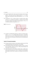
Example 10.15
The fact that a water stream emerging from a faucet “necks down” as it falls is
shown in Fig. 10.23, where A1 = 1.8 cm2 , A2 = 0.3 cm2 , and h = 25 cm. What is
the water flow rate from the faucet, assuming a steady flow?
Fig. 10.23
A1
h
A2
Solution: As water falls from a faucet, its speed increases due to gravity. Because
the volume flow rate must be the same at all cross sections, the stream must “neck
down”.
The flow of water is governed by the continuity Eq. 10.32, that is:
A1 v1 = A2 v2
where v1 and v2 indicate the speed of the water at the marked levels shown in
Fig. 10.23. Since water is falling freely, we must have:
v22 = v12 + 2gh
Eliminating v2 from the last two equations, we get:
v1 =
2ghA22
A21
− A22
=
2(9.8 m/s2 )(0.25 m)(0.3 cm2 )2
= 0.374 m/s
(1.8 cm2 )2 − (0.3 cm2 )2
10.5 Fluid Dynamics
333
The volume flow rate RV , given by Eq. 10.33, is thus:
RV = A1 v1 = (1.8 × 10⁻⁴ m2 )(0.374 m/s) = 6.732 × 10⁻⁵ m3 /s
Finally, we find the mass-flow rate Rm using Eq. 10.31 to be:
Rm = ρA1 v1 = ρRV = (103 kg/m3 )(6.735 × 10⁻⁵ m3 /s) = 0.067 kg/s
70 g/s
Example 10.16
Water flowing from a faucet of cross-sectional area A = 2 cm2 is used to fill a
bucket of volume V = 30 liters = 30 × 103 cm3 , see Fig. 10.24. What is the speed
v at which the water leaves the faucet if it takes exactly 1 minute to fill the bucket?
Fig. 10.24
A
Solution: According to the given information, the volume flow rate is:
RV = 30 liters/min = 500 cm3 /s
Using Eq. 10.33, RV = Av, we can find the speed v as follows:
v=
RV
500 cm3 /s
= 250 cm/s = 2.5 m/s
=
A
2 cm2
Bernoulli’s Equation
In static fluids, the pressure is the same at all points on the same horizontal level
but increases with depth. This is not generally true when the fluid is in motion. In
334
10 Mechanical Properties of Matter
the year 1738, Bernoulli derived an expression for an ideal fluid (i.e. a fluid that
is incompressible, non-viscous and flows in a non-rotational steady manner) that
relates the pressure, speed, and elevation within different locations in the fluid.
∗ Consider a small portion of a tube of flow of an ideal fluid with density ρ
through
a non-uniform pipe as shown in Fig. 10.25. The width of the tube in this figure is
exaggerated for clarity.
At time t
P2
A2
A1
y1
a'
a
b'
Δ
b
y2
.
P1 A1
.
s
w
Flo
A2
Δs
Fig. 10.25 The fluid in a section of length
At time t + Δ t
s1 moves to a section of length
s2 , while the volume of
the two sections are the same
Using the information in Fig. 10.25, we perform the following steps:
1. At some initial time t, the fluid lies between two cross sections A1 and A2 at two
points labeled a and b, respectively.
2. After a time interval t, the fluid’s ends undergo displacements s1 and s2 to
new points labeled a and b , respectively.
3. The volume of fluid that passes from point a to point a over a time t is equal to
the volume of fluid that passes from point b to point b in the same time interval,
that is V = A1 s1 = A2 s2 .
4. The force on the cross section A1 is P1 A1 and the force on the cross section A2 is
P2 A2 . Thus, the net work done on the fluid by these forces over the time t is:
W = P1 A1 s1 − P2 A2 s2 = (P1 − P2 ) V
(10.34)
where the negative sign in the second term is due to the fact that the fluid force
P2 A2 is opposite to the displacement s2 .
5. Part of this work goes into changing the kinetic energy of the fluid, and the other
part goes into changing its gravitational potential energy. If
m is the mass of the
10.5 Fluid Dynamics
335
fluid that passes through the tube during the time interval
t, then
m=ρ V
and the change in kinetic and potential energy will be given by:
K=
U=
1
2
mv22 −
mgy2 −
1
2
mv12 = 21 ρ V (v22 − v12 )
mgy1 = ρ V g(y2 − y1 )
(10.35)
(10.36)
6. We can now apply the work-energy theorem written in the form W = K + U,
where W is the work done by all applied forces and is given by Eq. 10.34. Thus:
(P1 − P2 ) V = 21 ρ V (v22 − v12 ) + ρ V g(y2 − y1 )
If we divide both sides by
V, we get:
P1 − P2 = 21 ρ(v22 − v12 ) + ρg(y2 − y1 )
(10.37)
7. Rearranging the terms, we get:
P1 + 21 ρv12 + ρgy1 = P2 + 21 ρv22 + ρgy2
(10.38)
This is the standard form of Bernoulli’s equation for non-viscous, incompressible
fluids experiencing steady flow. Since the subscripts 1 and 2 refer to any two points
along the tube flow, Bernoulli’s equation may also written as:
P + 21 ρv 2 + ρgy = constant
(10.39)
When the fluid is at rest, v1 = v2 = 0 and Bernoulli’s equation becomes:
P1 − P2 = ρg(y2 − y1 ) = ρgh
which is of the same form as Eq. 10.20.
When we take y to be constant, say y = 0, so that the fluid does not change elevation
as it flows, then Bernoulli’s equation becomes:
P1 + 21 ρv12 = P2 + 21 ρv22
(Horizontal flow)
(10.40)
This tells us that if the speed of a fluid increases as it travels horizontally, then its
pressure must decrease, and vice versa.
336
10 Mechanical Properties of Matter
Example 10.17
Gasoline of density ρ = 860 kg/m3 flows steadily through a horizontal pipe that
tapers in cross-sectional area from A1 = 1.5 × 10⁻³ m2 to A2 = 21 A1 , see Fig.
10.26. What is the volume flow rate when the pressure difference P1 − P2 is
5,160 Pa?
Solution: The flow of gasoline is governed by the continuity Eq. 10.32, i.e.
A1 v1 = A2 v2 . Then for A2 = 21 A1 we find:
A1 v1 = A2 v2
⇒
A1 v1 = 21 A1 v2
Fig. 10.26
P1
A1
⇒
v2 = 2v1
Flow
P2
1
A2
That is, the gasoline speed at the narrower section is twice that at the wider section.
Using this result in Bernoulli’s equation of a fluid traveling horizontally, see Eq.
10.40, we get:
P1 − P2 = 21 ρ(v22 − v12 ) = 21 ρ(4v12 − v12 ) = 23 ρv12
Thus, we can find v1 in terms of ρ and P1 − P2 as follows:
v1 =
2(P1 − P2 )
=
3ρ
2(5,160 Pa)
= 2 m/s
3(860 kg/m3 )
Finally, the volume flow rate RV , given by Eq. 10.33, is thus:
RV = A1 v1 = (1.5 × 10⁻³ m2 )(2 m/s) = 3 × 10⁻³ m3 /s