Hafez a radi, john o rasmussen auth principles of physics for scientists and engineers 17
Bạn đang xem bản rút gọn của tài liệu. Xem và tải ngay bản đầy đủ của tài liệu tại đây (721.48 KB, 30 trang )
388
12 Heat and the First Law of Thermodynamics
Stage D— Water-steam mixture remains at 100 ◦ C (even heat is added):
With a latent heat of vaporization LV = 2.26 × 10⁶ J/kg, the amount of
heat added QD until all of the water evaporates is:
QD = m LV = (1 × 10⁻³ kg)(2.26 × 10⁶ J/kg) = 2.26 × 10³ J
Stage E—Changing the temperature of steam from 100 to 150 ◦ C:
With a specific heat of steam cs = 2,010 J/kg.C◦ , the amount of heat
added QE is:
QE = ms cs T = (1 × 10⁻³ kg)(2,010 J/kg.C◦ )(50 C◦ )
101 J
The total heat added to change 1 g of ice at −50 ◦ C to steam at 150 ◦ C is Qtot =
3,224 J. That is, if we cool 1 g of steam at 150 ◦ C until we have ice at −50 ◦ C, we
must remove 3,224 J of heat.
Example 12.3
Find the quantity of heat required to convert ice of mass 500 g at −10 ◦ C into water
at 20 ◦ C. The specific heat of ice is ci = 2,220 J/kg.C◦ , the latent heat of fusion
is LF = 3.33 × 10⁵ J/kg, and the specific heat of water is cw = 4,186 J/kg.C◦ .
Solution: The ice gains heat throughout the following three stages.
Ice
at -10 oC
QA
Ice
at 0 oC
Fusion
QB
Water
at 0 oC
QC
Water
at 20 oC
In stage A we raise the temperature of ice from −10 to 0 ◦ C. Using Eq. 12.4 we
get:
QA = mi ci
T = (0.5 kg)(2,220 J/kg.C◦ )(10 C◦ ) = 11,100 J = 11.1 kJ
In stage B we melt the 500 g of ice at constant temperature (0 ◦ C) by supplying
the latent heat of fusion. Using Eq. 12.7 we get:
QB = m LF = (0.5 kg)(3.33 × 10⁵ J/kg) = 166,500 J = 166.5 kJ
In stage C we raise the temperature of water from 0 to 20 ◦ C. Using Eq. 12.4
we get:
12.1 Heat and Thermal Energy
QC = mw cw
389
T = (0.5 kg)(4,186 J/kg.C◦ )(20 C◦ ) = 41,860 J = 41.86 kJ
Note that QB > QC > QA and the total required heat is Qtot = 219.46 kJ.
Example 12.4
A glass beaker of water is at 20 ◦ C. The beaker has a mass mg = 200 g with specific
heat cg = 840 J/kg.C◦ and contains water of mass mw = 300 g with specific heat
cw = 4,186 J/kg.C◦ . A quantity of steam initially at 120 ◦ C is used to warm the
system to 50 ◦ C. If the specific heat of steam is cs = 2,010 J/kg.C◦ and latent heat
of vaporization is LV = 2.26 × 10⁶ J/kg, what is the mass of the steam?
Solution: The heat lost by the steam equals the heat gained by both beaker and
water. The steam loses heat over the stages shown below.
Water
at 50 oC
QC
Water Condensation Steam
at 100 oC
at 100 oC
QB
QA
Steam
at 120 oC
In the first stage, the steam is cooled from 120 to 100 ◦ C, i.e.
100 ◦ C − 120 ◦ C =
T = Tf − T i =
◦
− 20 C . The heat liberated in this stage by the unknown mass
ms of steam is:
QA = ms cs
T = ms (2,010 J/kg.C◦ )(−20 C◦ ) = −ms (40,200 J/kg)
In the second stage, the steam is condensed to water at 100 ◦ C. Since the latent
heat of condensation equals the latent heat of vaporization, we use Eq. 12.7 to find
the heat liberated as follows:
QB = −ms LV = −ms (2.26 × 10⁶ J/kg)
In the last stage the temperature of water is reduced from 100 to 50 ◦ C. This
liberates an amount of heat given by:
QC = ms cw
T = ms (4,186 J/kg.C◦ )(−50 C◦ ) = −ms (209,300 J/kg)
The heat lost is thus Qlost = QA + QB + QC = − ms (2,509,500 J/kg). The heat
gained by the beaker and water system from 20 to 50 C◦ is:
Qgained = mw cw
T + mg cg
T = (mw cw + mg cg ) T
= [(0.3 kg)(4,186 J/kg.C◦ ) + (0.2 kg)(840 J/kg.C◦ )](30 C◦ )
= 42,714 J
390
12 Heat and the First Law of Thermodynamics
If we equate the magnitude of heat lost by the steam, |Qlost |, with the heat gained
by the beaker and water system, Qgained , we get:
ms = 42,714 J/(2,509,500 J/kg) = 0.017 kg = 17 g
12.2
Heat and Work
In thermodynamics, when an isolated system is in thermal equilibrium internally, we
describe its macroscopic state with the variables P, V, and T to represent pressure,
volume and temperature. For such a system, we describe its microscopic state of
internal energy with the variable Eint (some other textbooks use the symbol U).
Let us assume our system consists of gas confined to a cylinder with insulated
walls and a movable frictionless piston of area A, as shown in Fig. 12.5. The cylinder
rests on a heat reservoir whose temperature T is controlled by a knob. At equilibrium,
the upward force on the piston due to the pressure of the confined gas is equal to the
weight of the load on the top of the piston.
Load
A
W
Piston
Insulation
P, V, T
Q
T
Heat reservoir
Control
knob
Fig. 12.5 Gas confined to a cylinder with a movable frictionless piston. The gas can do work W to raise
or lower the piston. By regulating the temperature T of the thermal reservoir, by means of a control knob,
a quantity of heat Q can be added or removed from the gas
Consider that we start at an initial state i, where the system is described to have
pressure Pi , volume Vi , and temperature Ti . We then change the system to a final
state f, described to have pressure Pf , volume Vf , and temperature Tf . The process
of changing the system from the initial state to the final state is a thermodynamic
process. During such a process, work is done by the system to raise the piston
12.2 Heat and Work
391
(positive work1 ) or lower it (negative work). In addition, heat may be transferred
into the system from the thermal reservoir (positive heat) or vice versa. We assume
that the state of the gas changes quasi-statically, i.e. slowly enough to allow the
system to remain essentially in a thermodynamic equilibrium at all times.
Now, assume we reduce the load from the piston in such a way that the piston will
move upward through a differential displacement d →
s with almost constant upward
→
force F , as shown in Fig. 12.6. From the definition of pressure, we have F = PA,
where A is the area of the piston. The differential work dW done by the gas during
the displacement is:
→
dW = F • d →
s = F ds = P A ds
Since A ds is the differential change in the volume of the gas dV (i.e. dV = A ds),
we can express the work done by the gas as follows:
dW = P dV
(12.10)
A
A
Load
dW
P
Reduced
load
ds
P
V
Before
V + dV
After
Fig. 12.6 A confined gas in a cylinder at pressure P does work dW on a free piston as the gas expands
from volume V to volume V + dV because of a decreased load
If the gas expands, as in Fig. 12.7, then dV is positive and the work done by the
gas is positive, whereas if the gas is compressed, dV is negative, indicating that the
work done by the gas is negative (which can be interpreted as work done on the gas).
When we remove an appreciable amount of load from the piston, the volume of the
gas changes from Vi to Vf , and the total work done by the gas is:
1 For historical reasons, we choose W to represent the work done by the system. In other parts of
the text, W is the work done on the system. This difference affects only the sign of W.
392
12 Heat and the First Law of Thermodynamics
Vf
W =
dW =
P dV
(12.11)
Vi
During the change in volume of the gas, the pressure and temperature of the gas may
also change. To evaluate the integral in the last equation, we need to know how the
pressure varies with volume. For example, Fig. 12.7 indicates that the work done by
the gas is represented by the area under the PV diagram of the figure.
P
P
Expansion
i
Pi
W= + Area under the curve
W> 0
Pf
Vi
f
Vf
Compression
f
Pf
W= - Area under the curve
W< 0
Pi
V
(a)
i
Vi
Vf
V
(b)
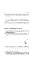
Fig. 12.7 The figure shows a gas that goes from an initial state i to a final state f by means of a
thermodynamic process. (a) When the gas expands, the work done by the gas is positive and equals the
area under the PV curve. (b) Similar to (a), except that the gas is compressed and the work done by the
gas is negative
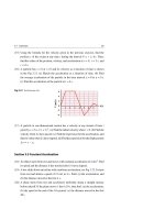
As seen from Fig. 12.7, the total work done during the expansion or compression
of the gas depends on the specific path taken from the initial state i to the final state f.
In Fig. 12.8, we illustrate this important point further by considering several different paths for the gas along the PV curve, from state i to state f, regardless of how
we achieve each path.
Path a—The gas expands from Vi to Vf while the pressure decreases from Pi to Pf .
The work done by the gas along this path is positive and represented by the colored
area under the curve between i and f.
Path b—The gas first expands from Vi to Vf at constant pressure Pi , and then its
pressure is reduced to Pf at constant volume Vf . The work done along this path is
Pi (Vf − Vi ).
Path c—The pressure of the gas is first reduced from Pi to Pf by cooling at a constant
volume Vi , and then allowing the gas to expand from Vi to Vf at constant pressure
Pf . The work done along this path is Pf (Vf − Vi ).
12.2 Heat and Work
393
Fig. 12.8 The gas of Fig. 12.5
goes from an initial state i to a
final state f by means of
P
Pi
i
Path a
several different
thermodynamic processes
Pf
f
W>0
Vi
P
Path b
i
Pi
V
Vf
W>0
f
Pf
Vi
V
Vf
P
i
Pi
Path c
Pf
f
W>0
Vi
V
Vf
P
f
Pf
Path d
i
Pi
W<0
Vf
Vi
V
P
Pi
i
Path e
Wnet > 0
f
Pf
Vi
Vf
V
Path d—The gas is compressed from Vi to Vf while the pressure increases from Pi
to Pf . The work done along this path is the negative of the colored area under the
curve.
394
12 Heat and the First Law of Thermodynamics
Path e—The net work done by the system during a closed cycle is the sum of the
positive work done during the expansion and the negative work done during the
compression. Here, the net work done by the gas is positive and is represented by
the enclosed area between the two curves.
From the graphs of Fig. 12.8, we see that W could be small or large depending on
the thermodynamic path between i and f. Thus:
Spotlight
The net work done by a system W depends on the thermodynamic process (or
the path) chosen between its initial and final states.
In a similar manner, we also find that the heat energy transfer Q into or out of
a system depends on the thermodynamic process. This can be demonstrated for an
ideal gas as shown in Fig. 12.9.
In Fig. 12.9a, the piston is held at a position where the gas is at its initial pressure
Pi , volume Vi , and temperature Ti . When the force holding the piston is reduced
slightly, the piston rises very slowly to a final pressure Pf and final volume Vf , i.e.
the gas is doing work W on the piston. During this expansion process, heat energy Q
is transferred from the reservoir to the gas to maintain a constant temperature Ti .
In Fig. 12.9b, the thermally insulated gas has the same initial state as in Fig. 12.9a,
but with a membrane replacing the piston. When the membrane is broken, the gas
expands rapidly into the vacuum until it acquires a pressure Pf and volume Vf . In
this case, the gas does no work, i.e. W = 0, and no heat is transferred, i.e. Q = 0.
Membrane
Very
slow
motion
Vacuum
P i Vi T i
P f V f Ti
Q
Heat reservoir at Ti
Heat reservoir at Ti
Insulation
Initial
(a)
Insulation
Final
P f V f Ti
Pi Vi Ti
Initial
Q=0
(b)
Final
Fig. 12.9 (a) An ideal gas at temperature Ti expands slowly while absorbing heat energy Q from a
reservoir in order to maintain its constant temperature Ti . (b) An ideal gas expands rapidly into an
evacuated chamber after a membrane is broken
12.2 Heat and Work
395
In both parts of Fig. 12.9, the initial and final states of the ideal gas are identical,
although the path is different. In part (a) of the figure the gas does work W on the
piston, and heat energy Q is transferred slowly to the gas from the reservoir. In part
(b) of the figure the work done by the gas is zero and no heat energy is transferred.
Thus:
Spotlight
The heat energy transfer Q depends on the thermodynamic process (or the
path) chosen between the initial and final states of a system.
Finally, we conclude that neither the work done nor the heat energy are independently conserved during a thermodynamic process between the initial and final states
of a system.
12.3
The First Law of Thermodynamics
In Chap. 6, we discussed the principle of conservation of energy as applied to systems that are not isolated, and we expressed this principle in Eq. 6.61, namely
W = Etot = K + U + Eint . In this chapter, we assume that there are no
changes in kinetic energy and potential energy of the system as a whole; that is,
K = U = 0 and hence W = Etot = Eint . Moreover, before this chapter, the
term work and the symbol W always meant the work done on a system. But starting from Eq. 12.10 and continuing to the rest of this chapter, we focus on the work
done by a system. Thus, we replace the symbol W by −W and Eq. 6.61 becomes
−W = Etot = Eint . If we need to account for the transfer of heat energy Q that is
added (if Q positive) or taken (if Q negative) from the system, then we add Q to the
left hand side of this equation and arrive at the following thermodynamic equation:
Eint = Q − W
(The first law of thermodynamics)
(12.12)
As we saw, W and Q are path-dependent, yet a surprising experimental discovery was found: The quantity Q − W is the same for all thermodynamic processes.
It depends only on the initial and final states of the system and is path-independent.
Equation 12.12 is known as the first law of thermodynamics. This law states that a
change in internal energy in a system can occur as a result of energy transfer by heat
or by work, or by both. If the thermodynamic system undergoes only a differential
change, we can write the first law as:
396
12 Heat and the First Law of Thermodynamics
dEint = dQ − dW
(The first law of thermodynamics)
(12.13)
Spotlight
The internal energy Eint of a system increases if energy is added via heat Q
and decreases if energy is lost via work W done by the system.
Some special cases of the first law of thermodynamics
are as follows
1. Isolated Systems
Consider a system that is not interacting with its surroundings. In this case, no energy
transfer by heat takes place, i.e. Q = 0, and the value of the work done by the system
is zero, i.e. W = 0. Then, from the first law we have Eint = 0. Thus, we conclude
that the internal energy of an isolated system remains constant.
Eint = constant
(Isolated system)
(12.14)
2. Cyclic Processes
Consider a non-isolated system that is taken through a cyclic process, i.e. a process
that starts and ends at the same state. In this case, the change in the internal energy
must again be zero, i.e.
Eint = 0. Then, from the first law we have:
Eint = 0
and
Q=W
(Cyclic process)
(12.15)
On the PV curve, a cyclic process appears as a closed curve as shown in path (e) of
Fig. 12.8. For this clockwise cyclic path, the net work done by the system (and Q)
equals the area enclosed by the path.
12.4
Applications of the First Law of Thermodynamics
The first law of thermodynamics relates the changes in internal energy of a system
to transfers of energy by work W or heat Q, or both. In this section, we consider
applications of the first law in processes in which certain restrictions are imposed.
12.4 Applications of the First Law of Thermodynamics
397
1. Adiabatic Process
An adiabatic process is one that occurs so rapidly or occurs in thermally insulated
systems during which no transfer of heat energy enters or leaves the system, i.e.
Q = 0. With this restriction and the application of the first law of thermodynamics
to an adiabatic process, we get:
Q=0
and
Eint = −W
(Adiabatic process)
(12.16)
Figure 12.10 shows an idealized adiabatic process. Heat cannot enter or leave the
system because of the insulation. The only way of transferring energy to the system
is by work. We see in this figure that if a gas is compressed adiabatically such that
W is negative, then Eint is positive and hence the temperature of the gas increases.
Conversely, if a gas expands adiabatically such that W is positive, then
negative, and hence the temperature of the gas decreases.
W>0
Eint is
W<0
Pf V f Tf
Insulation
Q=0
Pi Vi Ti
Tf < Ti
Ti
Expansion
Initial
Pf V f Tf
Q=0
T f > Ti
Compression
Fig. 12.10 An adiabatic compression/expansion is carried out for an ideal gas leading to an increase/
decrease in internal energy
Adiabatic processes have a very important role in mechanical engineering.
Some of the common examples include the approximately adiabatic compression/
expansion of a mixture of gasoline vapor and air that takes place during operation of
a combustion engine, leading to a temperature increase/decrease.
398
12 Heat and the First Law of Thermodynamics
2. Adiabatic Free Expansion Process
The free expansion process is an adiabatic process, i.e. Q = 0, in which no work is
done on or by the system, i.e. W = 0. Thus, with these restrictions and the application
of the first law we have:
Q=W =0
and
Eint = 0
(Free expansion)
(12.17)
Figure 12.11 shows how such an expansion can be carried out. An ideal gas in
thermal equilibrium is initially confined by a closed valve to one-half of an insulated
chamber; the other half is evacuated. When we open the valve, the gas expands freely
to fill both halves of the chamber. No heat is transferred to or from the gas because
of the insulation. No work is done by the gas because it rushes into vacuum, during
which its motion is unopposed by any counteracting pressure.
Q = W = 0 and Δ E int = 0
Insulation
Vi
Pi
Ti
Vacuum
Initial
Free
expansion
Pf
Ti
Pf
Ti
Vf
Final
Fig. 12.11 In a free expansion process there will be no change in internal energy or temperature between
the initial and final states
A free expansion differs from any other thermodynamic process since it cannot
be performed slowly in a controlled way. As a result, at any given instant during the
sudden expansion, the gas is not in thermal equilibrium and its pressure is not the
same everywhere.
3. Isobaric Process
An isobaric process is one that takes place at constant pressure. In general, the first
law of thermodynamics does not assume any special values for the isobaric process;
that is, Q, W, and Eint are all non-zero.
Assume the piston of Fig. 12.12 is free to move in such a way that it is always
in equilibrium under the effect of the net force from a gas pushing upwards and
12.4 Applications of the First Law of Thermodynamics
399
the weight of the piston plus the force due to atmospheric pressure pushing downwards. Then, an isobaric process could be established by transferring heat energy
Q to or from the gas by any mechanism. This transfer causes the gas to expand or
contract depending on the sign of Q. In the PV diagram of Fig. 12.8, the first process
in path (b) and the second process in path (c) are examples of isobaric processes.
Fig. 12.12 An isobaric
process could be achieved by
transferring heat energy to a
gas enclosed by a freely
W isobaric
Freely
moving
piston
Insulation
moving piston to attain a
constant pressure
Vi
P
Ti
Q
By any
mechanism
Constant pressure P
The work done by the gas as it expands or contracts in this isobaric process could
be obtained from Eq. 12.11, after removing the constant pressure from the integral,
as follows:
Wisobaric = P(Vf − Vi )
(Isobaric process)
(12.18)
4. Isovolumetric Process
An isovolumetric process is one that takes place at constant volume. In the PV
diagram of Fig. 12.8, the second process in path (b) and the first process in path (c)
are examples of isovolumetric processes.
Assume the piston of Fig. 12.13 is clamped to a fixed position to ensure an isovolumetric process. In such a process, the value of the work done by the gas is zero,
i.e. W = 0, because the volume does not change. Thus, with this restriction and the
application of the first law of thermodynamics to an isovolumetric process, we get:
W =0
and
Eint = Q
(Isovolumetric process)
(12.19)
400
12 Heat and the First Law of Thermodynamics
Fixed volume process
Fixed
piston
P i V i Ti
Insulation
Q
(Eint)i
Fixed
piston
Pf Vi Tf
(Eint)f
(Eint)f = (Eint)i + Q
Fig. 12.13 An isovolumetric process could be achieved by fixing the piston’s position. The pressure
increases, and all the transferred heat energy remains in the system as an increase in its internal energy
This expression specifies that if energy is added by heat to a system kept at constant
volume, then all of the transferred energy remains in the system as an increase in
its internal energy, and hence, temperature. For example, when a closed metallic
can is thrown into a fire, energy enters the gas in the can by the conduction of heat
through the metal walls of the can. The temperature, and thus the pressure, in the can
increases until the can possibly explodes, hence the warning label on such cans.
5. Isothermal Process
An isothermal process is one that takes place at constant temperature. This process
can be established by putting a gas container in contact with a constant-temperature
reservoir. If we plot P versus V at constant temperature for an ideal gas described
by Eq. 11.8, the plot yields a hyperbolic curve called an isotherm. In Chap. 13,
we will prove that the internal energy of an ideal gas is a function of temperature
only. Consequently, in an isothermal process involving an ideal gas we must have
Eint = 0. Therefore, for an isothermal process, we conclude from the first law that
the energy transfer Q must be equal to the work done by the gas W. That is:
Eint = 0
and
Q=W
(Isothermal process)
(12.20)
Any energy that enters the system by heat is transferred out of the system by work;
as a result, no change in the internal energy of the system occurs in an isothermal
process.
12.4 Applications of the First Law of Thermodynamics
401
Suppose that an ideal gas is allowed to expand at constant temperature as described
by the PV diagram in Fig. 12.14. According to Eq. 11.10, the curve is a hyperbola
with the equation PV = constant.
Fig. 12.14 The PV diagram
P
for an isothermal expansion of
Isotherm
an ideal gas from initial state i
to a final state f
i
Pi
PV=constant
f
Pf
Vi
Vf
V
Let us calculate the work done by the gas in the isothermal expansion from state
i to state f, as shown in Fig. 12.14. Because the gas is ideal and the process is quasistatic, we can use the expression PV = n RT for each point on the path. Therefore,
we have:
Vf
Vf
P dV =
W =
Vi
Vi
n RT
dV
V
(12.21)
Since T is constant and also n and R are constants, then they can be moved from the
integral sign. Thus:
Vf
W = n RT
Vi
where we used
dV
= n RT ln V
V
Vf
Vi
(12.22)
dV /V = ln V to evaluate the last integral. Thus:
W = n RT ln
Vf
Vi
(12.23)
If the gas expands, the work W equals the positive of the shaded area under the PV
curve shown in Fig. 12.14; this is because ln(Vf /Vi ) > 0. If the gas is compressed,
Vf < Vi , then ln(Vf /Vi ) < 0 and the work done is the negative of the area under the
PV curve.
402
12 Heat and the First Law of Thermodynamics
Table 12.3 summarizes the characteristics of the previous processes.
Table 12.3 The first law of thermodynamics in five special cases
Process
Restriction
Adiabatic
Q=0
Free expansion
Q=W =0
Isobaric
P = constant
Isovolumetric
V = constant, W = 0
Isothermal (ideal gas)
T = constant, Eint = 0
Consequence
Eint = −W
Eint = 0
Wisobaric = P(Vf − Vi )
Eint = Q
Q = W = n RT ln(Vf / Vi )
Example 12.5
At a constant pressure of 1 atm and a temperature of 0 ◦ C, the heat fusion of ice
is LF = 3.33 × 10⁵ J/kg, the density of ice is ρi = 920 kg/m3 , and the density of
liquid water is ρw = 1,000 kg/m3 . (a) Find the work W done by 1 kg of ice that
melts completely to water. (b) Find the change in internal energy of this process.
Solution: (a) The initial volume of ice is:
Vi = m/ρi = (1 kg)/(920 kg/m3 ) = 1.087 × 10⁻³ m3
The final volume of ice after it melts completely to water is:
Vw = m/ρw = (1 kg)/(1,000 kg/m3 ) = 10−3 m3
The work done by 1 kg of ice that melts completely to water under constant
pressure of 1 atm (1.01 × 10⁵ Pa) and temperature of 0 ◦ C, is:
Vw
W =
P dV = P(Vw − Vi )
Vi
= (1.01 × 10⁵ Pa)(10−3 m3 − 1.087 × 10⁻³ m3 ) = −8.787 J
−8.8 J
The minus sign appears because ice contracts when it melts.
(b) The heat energy transferred to change the phase of 1 kg of ice to water is:
Q = m LF = (1 kg)(3.33 × 10⁵ J/kg) = 3.33 × 10⁵ J
12.4 Applications of the First Law of Thermodynamics
403
Thus, from the first law of thermodynamics, we can find the change in internal
energy of this process as follows:
Eint = Q − W = 3.33 × 10⁵ J + 8.8 J = 3.330088 × 10⁵ J
We see from parts (a) and (b) that |W | is less than 0.003% of Q in this process, i.e.
|W |
Q. That is, the mechanical energy is negligible in comparison to the heat
of fusion. So, all the added heat of fusion shows up as an increase in the internal
energy.
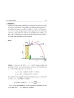
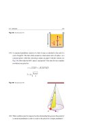
Example 12.6
At a constant pressure of 1 atm, a movable piston encloses 1 kg of water with a
volume of 10−3 m3 and a temperature of 100 ◦ C, see Fig. 12.15. Heat is added
from a reservoir until the liquid water changes completely into steam of volume
1.671 m3 , see the figure. (a) How much work is done by the system (water +
steam) during the boiling process? (b) How much heat energy is added to the
Freely moving piston
system? (c) What is the change in the internal energy of the system?
Insulation
Pa
Pa
Pa
Vi
Pa
Heat reservoir, 100 oC
Initial
Water
Q
Pa
Steam
Pa
Vf
Heat reservoir, 100 oC
Heat reservoir, 100 oC
Intermediate
Final
Fig. 12.15
Solution: (a) The work done by 1 kg of water that is converted completely into
steam under a constant pressure of 1 atm (1.01 × 10⁵ Pa) and a constant temperature of 100 ◦ C, is:
Vf
W =
Vi
P dV = P(Vf − Vi ) = (1.01 × 10⁵ Pa)(1.671 m3 − 10−3 m3 ) = 169 kJ
404
12 Heat and the First Law of Thermodynamics
(b) Since the heat of vaporization of water at atmospheric pressure is
2.26 × 10⁶ J/kg, the heat energy required to change the phase of 1 kg of water to
steam will be:
Q = m LV = (1 kg)(2.26 × 10⁶ J/kg) = 2,260 kJ
(c) From the first law of thermodynamics, we can find the change in internal
energy of this process as follows:
Eint = Q − W = 2.26 × 10⁶ J − 1.69 × 10⁵ J = 2,091 kJ
We see that about 92.5% of the heat energy goes into internal energy while the
remaining 7.5% goes into external work.
Example 12.7
An aluminum rod of mass 1 kg is heated from 25 to 55 ◦ C at constant atmospheric
pressure, see Fig. 12.16. The aluminum rod has a density ρ of 2.7 × 10³ kg/m3 ,
a coefficient of volume expansion β of 7.2 × 10⁻⁵ (C◦ )−1 and a specific heat c
of 900 J/kg.C◦ . (a) How much work is done by the rod? (b) How much heat is
transferred to the rod? (c) Quantify the rod’s internal energy change.
V+ΔV
V
T
T+ΔT
Fig. 12.16
Solution: (a) The initial volume of the aluminum rod is given by:
V =
m
1 kg
= 3.704 × 10⁻⁴ m3
=
ρ
2.7 × 10³ kg/m3
Using the change in temperature T = Tf − Ti = 55 ◦ C − 25 ◦ C = 30 C◦ , the
change in the rod’s volume can be obtained from Eq. 11.5 as follows:
12.4 Applications of the First Law of Thermodynamics
405
V =βV T
= (7.2 × 10⁻⁵ (C◦ )−1 )(3.704 × 10⁻⁴ m3 )(30 C◦ ) = 8 × 10⁻⁷ m3
Since the expansion is carried out at a constant pressure, the work done by the
aluminum rod is:
Vf
P dV = P(Vf − Vi ) = P V
W =
Vi
= (1.01 × 10⁵ Pa)(8 × 10⁻⁷ m3 ) = 8.08 × 10⁻² J
(b) We use the specific heat value in Eq. 12.4 to calculate the amount of heat
transferred to the rod as follows:
Q = m c T = (1 kg)(900 J/kg.C◦ )(30 C◦ ) = 2.7 × 10⁴ J
(c) From the first law of thermodynamics, we can find the change in internal
energy of this process as follows:
Eint = Q − W = 2.7 × 10⁴ J − 8.09 × 10⁻² J = 2.699 × 10⁴ J
We notice that almost all of the heat energy goes towards increasing the internal
energy of the aluminum rod. The fraction of heat energy that is used as work
against the atmospheric pressure is only about 4 × 10⁻⁴ %. Therefore, in thermal
expansion of solids, the amount of energy that goes into work is usually neglected.
Example 12.8
Find the work done by 1 kmol of an ideal gas that is kept at a constant temperature
of 27 ◦ C in an expansion process from 2 to 5 L.
Solution: Rewriting these values and the gas constant R, we have:
n = 1 kmol
R = 8.314 × 10³ J/kmol.K
T = 27 ◦ C = 27 + 273 = 300 K
Vi = 2 L = 2,000 cm3 = 2 × 10⁻³ m3
Vf = 5 L = 5,000 cm3 = 5 × 10⁻³ m3
406
12 Heat and the First Law of Thermodynamics
Since this process is isothermal, the work done by the ideal gas is given by
Eq. 12.23. Substitution in this equation results in:
W = n RT ln
Vf
Vi
= (1 kmol)(8.314 × 10³ J/kmol.K)(300 K) ln
5
2
= 2.29 × 10⁶ J
This means that the heat energy Q that must be given to the ideal gas from the
reservoir to keep its temperature T = 27 ◦ C is also 2.29 × 10⁶ J.
12.5
Heat Transfer
We discussed the transfer of heat energy between a system and its surroundings,
but we did not describe how that transfer takes place and at what rate. The three
common energy-transfer mechanisms that are responsible for changing the internal
energy state of a system are:
1. Conduction:
The flow of heat that reduces the temperature difference between two materials.
2. Convection:
The flow of heat in liquids or gases that carries heat from one place to another
if the liquids or gases are free to move.
3. Radiation:
The transfer of energy in the form of electromagnetic waves from objects that
have temperatures greater than absolute zero. The transfer of heat energy from
one location to another is by infrared radiation.
In this section we focus only on the first mechanism, leaving the other two mechanisms for other thermodynamic studies.
Thermal Conduction in One Dimension (Plain Walls)
In thermal conduction, heat transfer can be represented on the atomic scale as an
exchange of kinetic energy between microscopic particles (molecules, atoms, and
electrons) in which less energetic particles gain energy in collisions with more energetic particles. By this method, heat energy is transferred from the hot parts of an
object to its cold parts.
12.5 Heat Transfer
407
Consider the flow of heat along the x-axis between the faces of a slab of a material
of thickness x and face area A, as shown in Fig. 12.17. Assume the opposite faces are
maintained at different temperatures TH and TC , where TH > TC . Let T = TC − TH
denote the change in temperature that is maintained along the thickness
temperature difference TH − TC = − T is what gives rise to heat flow.
x. The
Fig. 12.17 Linear heat
transfer through a conducting
slab of face area A and
thickness
x, when the
TH
opposite faces are at different
temperatures, TH and TC
A
TC
Heat flow
TH > TC
Δx
o
x
Let Q be the heat energy that is transferred through the slab from its hot face
to its cold face, in a time interval t. Let H = Q/ t denote the rate of heat flow
across the slab (H is measured in watts). Experiments show that H should be directly
proportional to the face area A, the temperature difference − T = TH − TC > 0, and
inversely proportional to the thickness x. That is:
H=
Q
T
∝ −A
t
x
H=
T
Q
= −kA
t
x
or
(12.24)
where k is a proportionality constant that has the SI unit W/m.C◦ and is called the
thermal conductivity of the material. For a slab of differential thickness dx and
differential temperature difference dT, we can write what is called the law of heat
conduction as follows:
H = −kA
dT
dx
(12.25)
408
12 Heat and the First Law of Thermodynamics
where dT /dx is known as the temperature gradient. The minus sign in Eq. 12.25 is
due to the fact that heat energy flows in the direction of decreasing temperature.
Now, consider a long uniform rod of length L, as shown in Fig. 12.18. The rod is
insulated so that thermal energy cannot enter nor escape from its surface except at
its ends, which are in thermal contact with heat reservoirs having temperatures TH
and TC , where TH > TC .
Heat
reservoir
TH > TC
TH
A
Heat
reservoir
Insulation
Heat flow
TC
x
o
L
Fig. 12.18 Conduction of heat through a uniform conducting, insulated rod of length L and face area A,
where the opposite faces are at different temperatures, TH and TC (TH > TC )
When a steady-state has been reached, the temperature at each point along the rod
is constant in time. In such a case, the temperature gradient is the same everywhere
along the rod and is given by:
dT
TC − TH
=
dx
L
(12.26)
Thus, the rate of heat flow becomes:
H = kA
TH − TC
L
(12.27)
The thermal conductivity k is a constant that depends on the material of the rod.
Large values of k indicate that a material is a good thermal conductor, and vice versa.
Table 12.4 displays the thermal conductivities of some common metals, gases, and
building materials.
12.5 Heat Transfer
409
Table 12.4 Thermal conductivity of some substances around normal room temperature.
Substance
Thermal conductivity W/m.C◦
Metals
Stainless steel
14
Lead
35
Aluminum
238
Gold
314
Copper
401
Silver
427
Gases
Air (dry)
0.026
Helium
0.15
Hydrogen
0.18
Building materials
Foam
0.024
Rock wool
0.043
Fiberglass
0.048
Asbestos
0.08
Wood
0.08
Rubber
0.2
Glass
0.8
Concrete
0.8
Window glass
1.0
Steel
18
These values are approximate because k depends on the temperature
Example 12.9
A glass window measures 1 m × 1.5 m × 0.5 cm and has a thermal conductivity
of 0.8 W/m.C◦ . The temperature of the inner surface of the glass is TH = 20 ◦ C,
while the temperature for the outer surface is TC = −15 ◦ C, see Fig. 12.19. (a)
Calculate the rate of heat flow by conduction through the window. (b) If the inner
face of the window is taken to be at x = 0, see the figure, then find the temperature
of the glass as a function of x.
410
12 Heat and the First Law of Thermodynamics
Fig. 12.19
TH > TC
Glass
A
Heat
flow
TH
TC
o
Solution: (a) The thickness of the glass is
Δx
x = 0.5 cm = 5 × 10⁻³ m and the
T = TC − TH = −15 ◦ C − 20 ◦ C = −35 C◦ . Using
change in temperature is
Eq. 12.24 we get:
H = −kA
x
(−35 C◦ )
T
= −(0.8 W/m.C◦ )(1 m × 1.5 m)
= 8,400 W
x
5 × 10−3 m
This enormous rate of heat flow by conduction shows that glass is not a very
good insulator. The rate of heat flow through a glass window can be reduced
substantially by using two layers of glass with a thin air layer between them. This
is called double glazing.
(b) The temperature gradient for the window is given by:
dT
=
dx
T
(−35 C◦ )
=
= −7,000 C◦/m
x
5 × 10⁻³ m
This equation can be integrated to give:
T
x
dT = (−7,000 C◦/m)
dx
⇒
T − TH = (−7,000 C◦/m) (x − 0)
0
TH
T = 20 ◦ C − (7,000 C◦ /m) x
Thus:
We can check whether this gives the correct temperature of −15 ◦ C for the outer
surface as follows:
T = 20 ◦ C − (7,000 C◦ /m) (5 × 10⁻³ m) = −15 ◦ C
12.5 Heat Transfer
411
Example 12.10
Figure 12.20 shows two slabs of thickness L1 and L2 , thermal conductivities k1
and k2 , and an equal surface area A. The temperatures at the outer faces of the slabs
are TH and TC , where TH > TC . In a steady-state condition, find: (a) the interface
temperature T, when TH = 25 ◦ C, TC = −5 ◦ C, L2 = 2L1 , and k2 = 4k1 , and (b)
the rate of heat transfer by conduction through the slabs.
Heat
reservoir
TH > TL
Heat flow
Heat flow
TH
k1
Heat
reservoir
Insulation
k2
H1
H2
TL
A
L1
T
L2
Fig. 12.20
Solution: (a) If T is the temperature at the interface, then the rate of heat flow
through the two slabs is:
H1 = k1 A
TH − T
T − TC
, and H2 = k2 A
L1
L2
When a steady-state is reached, these two rates must be equal, that is:
k1 A
Solving for T gives:
TH − T
T − TC
= k2 A
L1
L2
T=
k1 L2 TH + k2 L1 TC
k1 L2 + k2 L1
Inserting the given relations and the known temperatures gives:
T=
2k1 L1 TH + 4k1 L1 TC
= 16 (2TH + 4TC ) = 16 [2(25 ◦ C) + 4(−5 ◦ C)] = 5 ◦ C
2k1 L1 + 4k1 L1
(b) The expression of the rate of heat flow by conduction will be:
H = H1 = H2 =
A (TH − TC )
10 A k1
=
(L1 /k1 ) + (L2 /k2 )
L1
412
12 Heat and the First Law of Thermodynamics
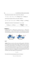
Home Insulation
Insulation is important in building houses, since it helps limit heat loss and hence
keeps homes at a comfortable temperature with less cost, see Fig. 12.21. Good insulation requires many insulation slabs.
Poor attic
insulation
Fig. 12.21 In houses, heat is conducted from the inside to the outside more rapidly where insulation is
poor. Thus, houses should be well insulated especially in the attic to minimize heat loss
For a compound slab containing several materials of thicknesses L1 , L2 , . . . and
thermal conductivities k1 , k2 , . . ., we can perform similar steps as in Example 12.10
to show that the rate of heat transfer at a steady-state will take the form:
H=
A (TH − TC )
,
Ln /kn
(n = 1, 2, . . .)
(12.28)
n
In the engineering practice, the term L/k for a particular substance is referred to
as the R value of the material, and Eq. 12.28 takes the following form:
H=
A (TH − TC )
, (n = 1, 2, . . .)
Rn
(12.29)
n
where Rn = Ln /kn . If a wall contains three slabs of insulation, then we can find the
value of R for the wall by adding the values of R for each slab. Table 12.5 lists the
R-values for common building materials.