Hafez a radi, john o rasmussen auth principles of physics for scientists and engineers 2 23
Bạn đang xem bản rút gọn của tài liệu. Xem và tải ngay bản đầy đủ của tài liệu tại đây (904.57 KB, 30 trang )
16.3 Standing Sound Waves
541
Example 16.4
Two sinusoidal sound waves, equal in amplitude and traveling in opposite directions along the x-axis, are superimposed on each other. The resultant wave is of
the form:
y = (2 m) sin
π
π
x cos
t
L
T
where x is in meters and t in seconds and the arguments of the sine and cosine functions are in radians. (a) What are the mathematical formulas of the two sinusoidal
sound waves that are superimposed to give this resultant? (b) Find the values of
the wavelength and the frequency of the two sinusoidal waves when L = 2 m and
T = 1 s. (c) What are the velocities of the two sinusoidal waves?
Solution: (a) Using the general form of the standing waves given by Eq. 16.11,
we find A = 1 m, k = π/L rad/m, and ω = π/T rad/s. Using Eq. 16.8, we find the
two sinusoidal waves as follows:
π
x−
L
π
y2 = (1 m) sin
x+
L
y1 = (1 m) sin
π
t ,
T
π
t
T
(b) Using k = 2π/λ, and ω = 2π f when L = 2 m and T = 1 s, we have:
k=
π
π
2π
= =
λ
L
2m
ω = 2π f =
π
π
=
T
1s
⇒
⇒
λ=4m
f = 0.5 s−1 = 0.5 Hz
(c) Using v = ω/k, we find the speed of each of the sinusoidal waves as follows:
v=
2π f
ω
=
= λf = (4 m)(0.5 s−1 ) = 2 m/s
k
2π/λ
The velocity of y1 is v1 = +2 m/s (in the direction of increasing x) and the velocity
of y2 is v2 = −2 m/s (in the direction of decreasing x).
16.4
Standing Sound Waves in Air Columns
In Chap. 14, we saw how a standing wave can be generated either on a stretched string
with fixed ends or when one end is fixed and the other is left free to move. We learned
542
16 Superposition of Sound Waves
that this happens when the wavelengths of the waves suitably match the length of the
string, in which case the superposition of the traveling and reflecting waves produce a
standing wave pattern. For such a match, the wavelength corresponds to the resonant
frequency of the string.
We can set up standing sound waves in air-filled pipes in a way similar to that for
strings. Here is how we can compare the two:
1. The closed end of a pipe is similar to the fixed end of a string in that it must
be a displacement node. This is because the pipe’s wall at this end does not
allow longitudinal motion of the air and acts like a pressure antinode (point of
maximum pressure variation).
2. The open end of a pipe acts like the end of a string that is free to move, so there
must be a displacement antinode there1 . This is because the pipe’s open end
allows longitudinal motion of the air and acts like a pressure node (point of no
pressure variation, since the end must remain at atmospheric pressure).
It is interesting to know how sound waves reflect from the open end of a pipe.
To get insight into this, we start with the fact that sound waves are in fact pressure
waves. Next, we know that any compression region must be contained inside the pipe
(between its two ends). Furthermore, any compression region that exists at an open
end is free to expand into the atmosphere. This change in behavior of the air inside
and outside the pipe is sufficient to allow some reflection.
With the boundary conditions of nodes and antinodes at the ends of air columns,
we must set the normal modes of oscillations as we did in the case of stretched
strings.
Air Columns of Two Open Ends
First, we consider a pipe of length L that is open at both ends. By representing the
horizontal displacement of air elements on the vertical axis and applying the boundary
condition that meets the case of two open ends, see Fig. 16.9, the normal modes of
oscillations can be explained by considering the following first three patterns:
(1) The first normal mode (the first harmonic, or the fundamental):
The simplest pattern is shown in Fig. 16.9a. There are two imposed antinodes
1 The antinode of an open end of a pipe is located slightly beyond the end because sound compression reaching an open end does not reflect until it passes the end. Therefore, the effective length
of the air column is little greater than the true length L of the pipe.
16.4 Standing Sound Waves in Air Columns
543
at the two ends and only one node in the middle of the pipe. Also, there is only
half a wavelength in the length L. Thus, this standing wave pattern has:
λ1 = 2L and f1 =
v
v
=
.
λ1
2L
(2) The second normal mode (the second harmonic):
The second pattern is shown in Fig. 16.9b. This pattern has three antinodes and
two nodes. This standing wave pattern has:
v
v
= = 2 f1
λ2
L
λ2 = L and f2 =
(3) The third normal mode (the third harmonic):
The third pattern is shown in Fig. 16.9c. This pattern has four antinodes and
three nodes. This standing wave pattern has:
v
3v
= 3 f1
=
λ3
2L
λ3 = 2L/3 and f3 =
L
λ1 = 2 L
(a)
A
A
N
λ1 =
f1=
n=1
First
harmonic
n=2
Second
harmonic
n=3
Third
harmonic
2L
λ2= L
(b)
A
N
A
N
A
f2=
λ2 =
L= 2 f 1
λ3 = 2 L 3
(c)
A
N
A
N
A
N
A
f3=
λ3 =3
2L= 3 f 1
Fig. 16.9 The first three standing wave patterns (a), (b), and (c) of a longitudinal sound wave established
in an organ pipe that is open to the atmosphere at both ends. The horizontal motion of air elements in
the pipe is displayed vertically by using a red color. The difference between successive harmonics is the
fundamental frequency f1 , and each harmonic is an integer multiple of the fundamental frequency f1
Generally, the relation between the wavelength λn of the various normal modes
and the length L of a pipe of two open ends is:
λn =
2L
, (n = 1, 2, 3, . . .)
n
(Pipe, two open ends)
(16.14)
544
16 Superposition of Sound Waves
Also, according to the relation f = v/λ, where the speed v of the sound wave
is the same for all frequencies, the resonance frequencies fn associated with these
modes are (see Fig. 16.9):
fn =
v
v
= n , (n = 1, 2, 3, . . .)
λn
2L
(Pipe, two open ends)
(16.15)
The expressions of λn and fn are the same as for the string, except that v is the speed of
waves on the strings as in Eq. 14.66, whereas v in Eq. 16.15 is the speed of sound in air.
The relation between the resonance frequencies and the fundamental frequency is:
fn = n f1 , (n = 1, 2, 3, . . .)
(Pipe, two open ends)
(16.16)
Air Columns of One Closed End
Second, we consider a pipe of length L that is open at one end and closed at the
other. By applying the boundary condition that meets this case, the normal modes of
oscillations can be explained by considering the following first three patterns:
(1) The first normal mode (the first harmonic, or the fundamental):
Fig. 16.10a shows the simplest pattern. The standing wave extends from an
antinode at the open end to the adjacent node at the closed end. The fundamental standing wave pattern has:
λ1 = 4 L and f1 =
v
v
.
=
λ1
4L
(2) The third normal mode (the third harmonic):
The next pattern is shown in Fig. 16.10b. This pattern has two antinodes and two
nodes. Thus, this standing wave pattern has:
λ3 = 4L/3 and f3 =
v
3v
= 3 f1
=
λ3
4L
(3) The fifth normal mode (the fifth harmonic):
The next pattern is shown in Fig. 16.10c. This pattern has four antinodes and
four nodes. Thus:
λ5 = 4L/5 and f5 =
v
5v
=
= 5 f1
λ5
4L
16.4 Standing Sound Waves in Air Columns
L
545
λ1 = 4 L
(a)
A
f1=
N
λ1 =
4L
n=1
First
harmonic
n=3
Third
harmonic
n=5
Fifth
harmonic
λ 3= 4L/ 3
(b)
A
N
A
N
f3=
λ3 = 3
4 L= 3 f 1
λ5= 4L 5
(c)
A
N
A
N
A
N
f5=
λ5 = 5
4 L= 5 f 1
Fig. 16.10 The first three standing wave patterns (a), (b), and (c) of a longitudinal sound wave established
in an organ pipe that is open to the atmosphere at only one end. The horizontal motion of air elements
in the pipe is displayed vertically by using a red color. The harmonic frequencies are the odd-integer
multiples of f1 , and the successive difference is 2 f1
Generally, λn and fn of the various normal modes for a pipe of length L with only
one end open are given as (see Fig. 16.10):
λn =
fn =
4L
, (n = 1, 3, 5, . . .)
n
(Pipe, one open end)
v
v
= n , (n = 1, 3, 5, . . .)
λn
4L
fn = nf1 , (n = 1, 3, 5, . . .)
(Pipe, one open end)
(Pipe, one open end)
(16.17)
(16.18)
(16.19)
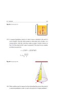
Figure 16.11 shows a simple apparatus for demonstrating the resonance of sound
waves in air columns. A tube that is open from both ends is immersed into a container
filled with water, and a tuning fork of unknown frequency f and wavelength λ is placed
at its top. The sound waves generated by the fork are reinforced when the length L
corresponds to one of the resonance frequencies of the tube. Thus:
λ=
v
v
4Ln
, f = =n
, (n = 1, 3, 5, . . .)
n
λ
4Ln
(16.20)
546
16 Superposition of Sound Waves
f =?
3l 4
l4
L
n=5
n=3
n=1
First harmonic
5l 4
Third harmonic
Fifth harmonic
Fig. 16.11 An apparatus used to demonstrate the resonance of sound waves in a tube closed at one end.
At resonance, L and λ are related
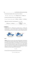
Example 16.5
When wind blows through a cylindrical drainage culvert of 2.5 m length, see
Fig. 16.12, a howling noise is established. Take v = 343 m/s as the speed of sound
in air. (a) Find the frequencies of the first three harmonics if the pipe is open at
both ends. (b) How many of the harmonics fall within the normal human hearing
range (from about 20 Hz → 20,000 Hz). (c) Answer part (a) if the pipe is blocked
at the other end.
Fig. 16.12
Solution: (a) When the pipe is open at both ends, we use Eq. 16.15 with n = 1 to
find the fundamental frequency as follows:
f1 = 1 ×
343 m/s
v
=
= 68.6 Hz
2L
2 × 2.5 m
Also, all harmonics are available for a pipe open at both ends; thus:
f2 = 2f1 = 137.2 Hz and f3 = 3 f1 = 205.8 Hz
16.4 Standing Sound Waves in Air Columns
547
(b) We can express the frequency of the highest harmonic heard as fn = n f1 ,
where fn = 20,000 Hz and n is the number of harmonics that can be heard. Therefore:
n=
fn
20,000 Hz
= 292
=
f1
68.6 Hz
Although we get n = 292, practically, only the first few harmonics have amplitudes
that are sufficient to be heard.
(c) Using Eq. 16.18 and substituting with n = 1, the fundamental frequency of
a pipe closed at one end will be given by:
f1 = 1 ×
343 m/s
v
=
= 34.3 Hz
4L
4 × 2.5 m
In this case, only the odd harmonics can exist. Thus:
f3 = 3 f1 = 102.9 Hz and f5 = 5 f1 = 171.5 Hz
Example 16.6
A background noise in a hall sets up a fundamental standing wave frequency in a
tube of length L = 0.7 m. What is the value of this fundamental frequency if your
ear blocks one end of the tube (see Fig. 16.13a) and when your ear is far from the
tube (see Fig. 16.13b)? Take v = 343 m/s as the speed of sound in air.
Noise
L
(a)
Noise
Ear
L
(b)
Ear
Fig. 16.13
Solution: When the tube is blocked by your ear (see Fig. 16.13a) the fundamental
frequency is given by Eq. 16.18 with n = 1:
f1 = 1 ×
343 m/s
v
=
= 122.5 Hz
4L
4 × 0.7 m
In addition, you can hear frequencies that are odd integer multiples of 122.5 Hz
provided that the standing waves are formed with sufficient amplitudes.
548
16 Superposition of Sound Waves
When you move your head away enough (see Fig. 16.13b) the pipe becomes
open at both ends and the fundamental frequency will be given by Eq. 16.15 with
n = 1:
f1 = 1 ×
v
343 m/s
=
= 245 Hz
2L
2 × 0.7 m
In addition, you can hear frequencies that are multiples of 245 Hz if the standing
waves are formed with sufficient amplitudes.
Example 16.7
Resonance can occur in Fig. 16.14 when the smallest length of the air column is
L = 9.8 cm. Take v = 343 m/s as the speed of sound in air. (a) What is the frequency
f of the tuning fork? (b) What is the value of L for the next two resonances?
Fig. 16.14
L = 9.8 cm
n=1
First resonance
Solution: (a) When the tube is blocked by the water’s surface, it acts as if the
tube is closed at one end. Thus, for the smallest air column L1 , the fundamental
frequency is given by Eq. 16.20 with n = 1:
f =1×
v
343 m/s
= 875 Hz
=
4L1
4 × (0.098 m)
First resonance
First harmonic
This frequency must be equal to the frequency f of the tuning fork.
(b) We know from Fig. 16.14 and Eq. 16.20 that the wavelength of the fundamental mode is four times the length of the air column. Thus:
λ=
4L1
= 4(0.098 m) = 0.392 m
1
16.4 Standing Sound Waves in Air Columns
549
Because the frequency of the tuning fork is constant, then according to Fig. 16.11,
the values of L for the next two normal modes are:
L3 =
3λ
3 × (0.392 m)
=
= 0.294 m = 29.4 cm
4
4
L5 =
16.5
5 × (0.392 m)
5λ
=
= 0.49 m = 49 cm
4
4
Second resonance
Third harmonic
Third resonance
Fifth harmonic
Temporal Interference of Sound Waves: Beats
Previously, we discussed the spatial interference of waves of same frequencies,
where at fixed time the amplitude of the oscillating elements varies with the position
in space. The standing waves in strings and air columns are good examples of this
kind of interference.
Now, we consider another type of interference of waves having a slight difference
in their frequencies, where at fixed position, the amplitude of the oscillating elements
varies periodically with time. The standing wave produced by two tuning forks having
a slight difference in their frequencies is a good example of this kind of interference.
We refer to this interference in time by temporal interference, and this phenomenon
is called beating:
Beating
Beating is defined as the periodic variation in amplitude at a fixed position due
to the variation in the constructive and destructive interference between waves
having slightly different frequencies.
Consider the time-dependent variations of the displacements of two sound waves
of equal amplitude and slightly different frequencies f1 and f2 (angular frequencies
ω1 = 2π f1 and ω2 = 2π f2 ) such that:
y1 = A cos(k1 x − ω1 t),
y2 = A cos(k2 x − ω2 t)
(16.21)
550
16 Superposition of Sound Waves
At the fixed point x = 0 (chosen for convenience), the two wave functions become
(see Fig. 16.15a):
y1 = A cos ω1 t,
(16.22)
y2 = A cos ω2 t
y 1 = A cos 2 π f 1 t ,
f 1 = 11 Hz
y 2 = A cos 2 π f 2 t ,
f 2 = 9 Hz
y
1
(a)
t
y
2
y
y = y 1 + y 2 = [2 A cos π ( f 1 − f 2 ) t ] cos π ( f 1 + f 2 ) t
Oscillates with an average frequency f av = ( f 1+f 2 ) /2
(b)
t
[± 2 A cos π ( f 1 − f 2 ) t ]
Tbeat = 1/ f 1 − f 2
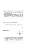
Fig. 16.15 (a) Formation of beats by combining two waves of slightly different frequencies f1 and f2
(f1 = 11 Hz and f1 = 9 Hz). (b) The slowly varying amplitude envelope ±2 A cos π(f1 − f2 ) t limits the
amplitude of the rapid sinusoidal function cos π(f1 + f2 ) t, which proceeds with an average frequency
fav = (f1 + f2 )/2
The superposition of y1 and y2 gives the following resultant:
y = y1 + y2 = A [cos ω1 t + cos ω2 t]
(16.23)
To simplify this expression, we use the trigonometric identity:
cos a + cos b = 2 cos 21 (a − b) cos 21 (a + b)
(16.24)
16.5 Temporal Interference of Sound Waves: Beats
551
If we substitute a = ω1 t and b = ω2 t in this identity, then the resultant wave
y reduces to:
y = [2 A cos 21 (ω1 − ω2 ) t] cos 21 (ω1 + ω2 ) t
(16.25)
When the difference in angular frequencies is small compared to the sum of angular
frequencies, i.e.:
|ω1 − ω2 |
ω1 + ω2
or
|f1 − f2 |
f 1 + f2
(16.26)
Then the time behavior of the factor cos 21 (ω1 + ω2 ) t, is a rapidly varying sinusoidal
oscillation, see Fig. 16.15b, with the average angular frequency 21 (ω1 + ω2 ). Thus,
the y equation indicates that the resultant sound wave at any given location has an
effective angular frequency equal to the average angular frequency:
ωav =
ω1 + ω2
2
or
fav =
f1 + f2
2
(16.27)
In addition, the oscillation is not precisely sinusoidal because the resultant amplitude
varies with time according to the expression:
Ares = 2 A cos 21 (ω1 − ω2 ) t
(16.28)
This resultant amplitude is a slowly varying envelope in time, see Fig. 16.15b, that
modulates the rapidly oscillating factor cos 21 (ω1 + ω2 ) t. Moreover, this resultant
amplitude Ares confirms the existence of a constructive interference when cos 21 (ω1 −
ω2 ) t = ±1. That is when:
1
|ω1 − ω2 | t = 0, π, 2π, . . . (Constructive interference)
2
(16.29)
Also, the resultant amplitude Ares confirms the existence of a destructive interference
when cos 21 (ω1 − ω2 ) t = 0. That is when:
3
5
1
1
|ω1 − ω2 | t = π, π, π, . . . (Destructive interference)
2
2
2
2
(16.30)
The time between successive moments of constructive (or destructive) interferences
is called the beat period, Tbeat . During this time, the phase difference increases by
π, i.e. 21 |ω1 − ω2 | Tbeat = π. Thus:
Tbeat =
1
2π
=
|ω1 − ω2 |
|f1 − f2 |
(16.31)
552
16 Superposition of Sound Waves
Hence, the number of beats per second, or the beat frequency fbeat , will be given by:
fbeat = |f1 − f2 |
(16.32)
Musicians can use the beat phenomenon in tuning their instruments. If an instrument sounds different from how it is supposed to, it can be tuned by using a standard
frequency until the beat disappears.
Example 16.8
Two identical violin A strings (see the left part of Fig. 16.16) of the same length
and tension are tuned exactly to 440 Hz. The tension in one of them is increased
by 2% (see the right part of Fig. 16.16). When both strings are struck, what will
be the beat frequency between their fundamental frequencies?
G
D
E A
String 1
String 2
.
L
t1, m
.
L
t2, m
.
.
Fig. 16.16
Solution: The frequency of a string that is fixed at both ends is given by
√
Eq. 14.68 as f = τ/μ/(2L), where L, τ, and μ are the length, tension, and
mass per unit length of the string, respectively. Thus, the ratio of frequencies of
the two strings after being struck is:
f2
1
=
f1
2L
τ2
μ
1
2L
τ1
=
μ
τ2
τ1
When tension τ2 is 2% more than τ1 , we can find the frequency f2 of string 2 as
follows:
f2
=
f1
1.02τ1 √
= 1.02 = 1.01
τ1
⇒
f2 = 1.01 f1 = 1.01 × (440 Hz) = 444 Hz
16.5 Temporal Interference of Sound Waves: Beats
553
With the use of Eq. 16.32, the beat frequency will be:
fbeat = |f1 − f2 | = |440 Hz − 444 Hz| = 4 Hz = 4 beat/s
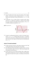
Example 16.9
A musician wants to tune the A2 key (key No. 25) of a piano that has a proper fundamental frequency of 110 Hz, see Fig. 16.17. Assume he uses a fork of frequency
f1 = 220 Hz and was able to tune the A2 key after observing a beat frequency of
8 Hz. Explain the process of tuning and find the mistuned frequency.
Brand
F# G# A#
22 24 26
F
21
Piano keyboard
G
23
A
25
B
27
C# D#
29 31
C
28
D
30
110 Hz
E
32
F# G# A#
34 36 38
F
33
G
35
A
37
B
39
220 Hz
Fig. 16.17
Solution: Equation 16.25 leads to the beat phenomenon when the frequencies are
close to each other, which is not the case for 110 and 220 Hz. However, based on
Eq. 14.69 of fixed strings, the proper second harmonic of the string of the A2 key
should be:
f2 = 2 × (110 Hz) = 220 Hz (Proper second harmonic)
By listening to the beats of 8 Hz between the fundamental frequency f1 = 220 Hz
of the tuning fork and the unknown mistuned second harmonic frequency f2 of
the A2 key, he can adjust the tension in the string until the beat note disappears.
From the beats Eq. 16.32, he can find the mistuned frequency of the A2 key as
follows:
fbeat = |f1 − f2 |
8 Hz = |220 Hz − f2 |
554
16 Superposition of Sound Waves
Hence,
f2 =
⎧
⎪
⎪
⎨ 228 Hz
or
⎪
⎪
⎩ 212 Hz
Accordingly, the musician cannot tell whether the mistuned fundamental frequency of the string was 114 Hz or 106 Hz, because both frequencies produce the
same beat frequency.
16.6
Exercises
Sections 16.1 and 16.2 Superposition and Interference and Spatial
Interference of Sound Waves
(1) Two traveling waves are defined by the following relations:
y1 = (2 cm) sin(kx − ω t),
y2 = (2 cm) sin(kx − ω t + φ)
Find the amplitude of the resultant wave y = y1 + y2 when φ = π/2 and φ = π.
(2) Two traveling waves are defined by the following relations:
y1 = (1.5 m) sin(10x − 16t),
y2 = (1.5 m) sin(14x − 20t)
where x is in meters, t is in seconds, and the arguments of the sine waves are in
radians. (a) What is the phase difference between the two waves when x = 4 m
and t = 2 s? (b) At t = 4 s, apply the condition of destructive interference (phase
difference = (2n + 1)π, n = 0, 1, 2, . . .) to find the closest positive value of x
to the origin.
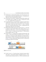
(3) The two identical speakers shown in Fig. 16.18 are driven by one oscillator that
has a frequency of 3,400 Hz. Take the speed of sound to be 343 m/s. (a) What
are the values of x that correspond to a minimum sound intensity at point
P? (b) What are the values of x that correspond to a maximum sound intensity
at point P?
(4) A small speaker is placed in a circular pipe of radius r = 1.35 m, as shown
in Fig. 16.19. Take the speed of sound to be 343 m/s and assume propagation
16.6 Exercises
555
of one-dimensional waves for such a big radius. What are the three smallest
frequencies that produce a maximum sound intensity in the tube?
Fig. 16.18 See Exercise (3)
L
P
L-x
Fig. 16.19 See Exercise (4)
r
(5) Two identical speakers, S1 and S2 , are placed vertically at a distance d apart.
They emit sound waves driven by the same oscillator whose frequency is f.
A listener at a distance R from the lower speaker walks straight towards it as
shown in Fig. 16.20. If the speed of sound is v, show that the listener will hear
a minimum sound when R satisfies the following relation:
R2 =
d 2 − (2n + 1)2 (v/2f )2
, (n = 0, 1, 2, . . .)
2(2n + 1)(v/2f )
Destructive
interference
(6) In the previous example, assume that d = 3 m, f = 350 Hz, and v = 343 m/s.
How many times will the listener hear a minimum in sound intensity while
walking from a very far point to the nearest possible point in front of the lower
speaker?
Section 16.3 Standing Sound Waves
(7) Two waves are traveling in opposite directions and are described by the following relations:
y1 = A sin(kx − ω t),
y2 = 21 A sin(kx + ω t)
556
16 Superposition of Sound Waves
Show that the resultant of these two waves can be written as a combination of
a traveling wave and a standing wave of the following form:
y = y1 + y2 = 21 A sin(kx − ω t) + (A sin kx) cos ω t
d
L
S1
R
S2
Fig. 16.20 See Exercise (5)
(8) Two identical speakers facing each other as shown in Fig. 16.21, establish a
standing wave as a result of the production of the following two oppositely
traveling sound waves:
y1 = (2 cm) sin(2.5x − 5t),
y2 = (2 cm) sin(2.5x + 5t).
where x and y are in centimeters and t is in seconds. (a) What is the amplitude of
the simple harmonic motion of an element of the medium located at x = 4 cm?
(b) Find the position of the nodes and antinodes. (c) What is the maximum
amplitude of an element at an antinode?
(9) The two sources shown in the evacuated vessel of Fig. 16.22, are 1.2 m apart,
and send sound waves of speed v = 2 m/s. Source S1 vibrates according to
the equation (0.04 m) sin 10π t while source S2 vibrates according to the
equation (0.01 m) sin 10π t. (a) Show that S1 sends sound in the positive x
direction as:
y1 = (0.04 m) sin(5π x1 − 10π t)
where x1 is measured from an origin located at S1 . (b) Show that S2 emits sound
in the negative x-direction as:
16.6 Exercises
557
y2 = (0.01 m) sin(5π x2 + 10π t)
where x2 is measured from an origin located at S2 . (c) Show that the equation
of motion of a particle at 0.8 m from S1 and 0.4 m from S2 is given by:
y = y1 + y2 = (−0.03 m) sin 10π t.
Standing wave
Speaker
Speaker
x
0
Fig. 16.21 See Exercise (8)
S1
0.4 m
0.8 m
1.2 m
S2
P
Fig. 16.22 See Exercise (9)
(10) Using direct substitution, show that the standing wave function:
y = 2 A cos
φ
2
sin kx − ω t +
φ
2
is a solution of the general partial linear differential equation [see Eq. 14.58]:
1 ∂ 2y
∂ 2y
−
=0
∂x 2
v 2 ∂t 2
Section 16.4 Standing Sound Waves in Air columns
Note: Unless otherwise specified, use the speed of sound in this section to be 343 m/s.
(11) An organ pipe of length 30 cm is open at both ends. What are the frequencies
of the fundamental and the next two harmonics?
(12) If the organ pipe in the previous exercise has one end closed, what are the
frequencies of the fundamental and the next two harmonics?
558
16 Superposition of Sound Waves
(13) The fundamental frequency of a pipe is found to be 110 Hz when the speed of
sound is 330 m/s. (a) Find the pipe’s length when it is closed at one end. (b) Find
the pipe’s length when it is open at both ends.
(14) The two adjacent harmonic frequencies of an organ pipe (with both ends open)
are determined to be 540 Hz and 420 Hz. (a) Find the fundamental frequency of
the pipe. (b) Find the pipe’s length.
(15) Estimate the fundamental frequency that you would experience when blowing
across the top of an empty cylindrical soft drink bottle that has a height of
10 cm. Assume that the bottle behaves like a tube with one end closed. Take the
speed of sound to be 340 m/s. How would this frequency change if the bottle
was only three quarters empty?
(16) What would be the range of an adjustable pipe length that has two open ends
if its fundamental frequency spans the human hearing rang (form 20 Hz to
20 kHz)? Take the speed of sound to be 340 m/s.
(17) A tuning fork vibrating at a frequency of 384 Hz is held over the top end of a
vertical tube while the other end is partially inserted in a water tank as shown
in Fig. 16.23. The water level in the tube is lowered by opening a valve in the
tank so that the length L of the air column slowly increases from an initial value
of 30 cm. Determine the next two values of L that correspond to resonance.
Fig. 16.23 See Exercise (17)
L
(18) Assume that the speed of waves on a guitar string does not change when the
string is fingered. If an unfingered string has a length L = 0.75 m and is tuned
to play an F note (at 349 Hz). (a) How far from the end of this string must your
finger be placed to play an A note (at 440 Hz). (b) What is the wavelength
of the standing wave when this fingered string resonates at its fundamental
frequency? (c) Find the frequency and wavelength of the sound waves that are
produced by this string at that fundamental frequency.
16.6 Exercises
559
(19) At a temperature of 25 ◦ C, an open organ pipe produces the middle C note
(262 Hz) with a fundamental standing wave. (a) What is the length of the
pipe? (b) Find the frequency and wavelength of the fundamental standing wave
in the pipe. (c) Find the frequency and wavelength of the sound produced in the
air outside the pipe.
(20) An open organ pipe is tuned in a room where the temperature was set to 20 ◦ C.
If the temperature drops to 10 ◦ C, what would be the percentage change in
frequency generated by the pipe?
(21) In an air-filled tube closed at both ends, the distance between several nodes
is 25 cm. When another gas replaces the air, the distance between that same
number of nodes is 35 cm. If the speed of sound in air is 340 m/s, what is the
speed in the gas?
(22) An organ pipe can resonate at the successive harmonics of frequencies 210,
350, and 490 Hz. (a) Is this pipe open at both ends or closed at one of its
ends? Explain why. (b) What is the fundamental frequency of this pipe?
(23) A tube is open at both ends and has a length L = 2 m. It resonates at two successive harmonics of frequencies 355 and 440 Hz. (a) What is the fundamental
frequency of this pipe? (b) What is the speed of sound in the air inside the tube?
(24) A tube has a length L = 2.5 m. How many harmonics are present in this tube
within the human hearing range (from 20 Hz to 20 kHz) if: (a) the tube is open
at both ends, and (b) is closed at one end?
(25) A pipe is open at one end and closed by a movable piston at the other end.
A tuning fork of frequency 348 Hz is held at the open end. On a hot day a
resonance occurs when the piston is at 0.25 m from the open end and again
when it is at 0.75 m, see Fig. 16.24. (a) What is the speed of sound in the air
inside the pipe? (b) How far from the open end will the piston be when the next
resonance is experienced?
Fig. 16.24 See Exercise (25)
25cm
First resonance
75 cm
Piston
Second resonance
560
16 Superposition of Sound Waves
Section 16.5 Temporal Interference of Sound Waves: Beats
(26) Determine the beat frequency resulting from the superposition of the two sound
waves given by:
y1 = (1.5 cm) sin(3.5x − 1376π t),
y2 = (1.5 cm) sin(3.5x − 1364π t).
where x and y are in centimeters and t is in seconds.
(27) Two identical violin strings have the same length L, tension τ, and exact fundamental frequency of 600 Hz. How much should we increase the tension of
one of these strings to generate a sound beat of 6 Hz (see Fig. 16.25 for a new
tension τ1 )?
Fig. 16.25 See Exercise (27)
L
String 1
t ,m
L
String 2
t1 , m
(28) A standard tuning fork of frequency 512 Hz makes a beat frequency of 4 Hz
with another fork of unknown frequency. The beat frequency disappears when
the prongs of the second fork are waxed. What is the frequency of the unknown
fork?
(29) A mistuned Middle C string in a piano (corresponds to key No. 40) has a proper
fundamental frequency of 262 Hz, see Fig. 16.17. During the tuning trials, a
musician hears 3 beats per second between the piano string and a standard
oscillator of 262 Hz. (a) What are the possible frequencies of the string? (b)
When the musician tightens the string slightly, he hears 4 beats per second.
What is the frequency of the string now? (Hint: use the fact that tightening
the string raises the wave speed and frequency) (c) By what percentage should
the musician change the tension in the string to tune it?
(30) At a temperature of 30 ◦ C, a source generates sound waves that propagate in the
air with wavelengths λ1 = 1.62 m and λ2 = 1.70 m. (a) What beat frequency is
heard? (b) How far in space is the distance between the maximum intensities?
(Hint: see Fig. 16.15b)
Light Waves and Optics
17
Since ancient times, the nature and properties of light have been intensively investigated in an attempt to address many of our needs for a better life on Earth. Today,
scientists view the behavior of light as waves (electromagnetic waves) in some situations and particles (photons) in other situations. In this chapter, we briefly introduce
aspects of light that are understood best when using wave models, as applied to
geometrical and physical optics. First, we study the reflection and refraction of
light at the boundary between two media. Then we study formation of images when
using the two types of mirrors and lenses.
17.1
Light Rays
It is useful to represent light waves with imaginary surfaces representing the crests
of the electric field of the electromagnetic waves. These surfaces are called wave
fronts, and the distance between any two successive wave fronts is referred to as
the wavelength λ. While propagating in vacuum, light waves have a constant speed
c = λ f, where c = 2.9979 × 10⁸ m/s 3 × 10⁸ m/s and f is the light’s frequency.
When we study light reflection from mirrors, refraction from a surface between
two media, and propagation through lenses, we approximate light propagation by
defining rays that travel in straight lines perpendicular to the wave fronts. This ray
approximation technique is referred to as geometrical optics. On the other hand,
when we study interference, diffraction, and polarization of light and need to get
satisfactory descriptions of these phenomena, we treat light as waves. Such a study
is referred to as physical optics.
H. A. Radi and J. O. Rasmussen, Principles of Physics,
Undergraduate Lecture Notes in Physics, DOI: 10.1007/978-3-642-23026-4_17,
© Springer-Verlag Berlin Heidelberg 2013
561
562
17 Light Waves and Optics
In geometrical optics we first consider a point source S emitting light waves
isotropically in all directions in a uniform medium. The emitted waves are a series
of concentric spherical wave fronts with the source located at their common centers,
and these waves can be approximated by straight-line rays perpendicular to the wave
fronts, see Fig. 17.1a. Next, we consider the case when the source is very far and study
the propagation of plane wave fronts. In this case, light rays propagate as straight
lines perpendicular to the wave fronts in a given direction, see Fig. 17.1b.
Wave Fronts
Ray
c
λ
Ray
λ
c
λ
λ
λ
Ray
c
(a)
c
Rays
c
c
c
Ray
c
c
S
c
λ
Wave Fronts
(b)
Fig. 17.1 Light waves of wavelength λ propagating with a speed c as: (a) spherical wave fronts and
(b) plane wave fronts
Spotlight
We observe the following effects when plane wave fronts meet a barrier with
a circular opening of diameter a:
• If λ
a, the rays of the wave continue to move away from the opening in
straight lines, see Fig. 17.2a.
• If λ ≈ a, the rays of the wave spread out from the opening in all directions,
see Fig. 17.2b. This effect is called diffraction.
• If λ > a (or λ a) the rays of the wave spread out more (diffracted more)
in a way as if the opening is a point source, see Fig. 17.2c.
17.1 Light Rays
λ
563
Sharp
shadow
More
Diffraction
Diffracted
Rays
Ray
ca
Ray
c
c
Ray
λ≈a
λ a
Wave Fronts
a
a
(a)
λ a
(b)
(c)
Fig. 17.2 A plane wave of light of wavelength λ is incident on a barrier that has a circular opening
of diameter a. (a) When λ
a, the rays continue in a straight line and the ray approximation is valid.
(b) When λ ≈ a, the rays spread out from the opening in all directions. (c) When λ > a (or λ
a) the
circular opening behaves like a point source
17.2
Reflection and Refraction of Light
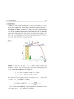
Figure 17.3 shows a beam of light of wavelength λ1 and speed v1 represented by a
light ray traveling in a straight line in medium 1. The beam encounters the smooth
boundary surface (or interface) of the transparent medium 2, which is more dense
than medium 1. Part of the incident light is reflected by the surface and another part
penetrates medium 2 with wavelength λ2 and speed v2 . Unless the incident beam is
perpendicular to the surface, the ray that enters medium 2 is bent at the boundary
and is said to be refracted.
Normal
Incident ray
Medium 1
θ1
θ1′ = θ 1
1
Reflected ray
1
Interface
Medium 2
2
θ2
Refracted ray
Fig. 17.3 An incident ray in medium 1 is reflected from the interface and maintains the same speed v1 ,
while the refracted ray is bent toward the normal and propagates in medium 2 with a speed v2 < v1
564
17 Light Waves and Optics
In Fig. 17.3, the incident, reflected, and refracted rays are all in a plane perpendicular to the boundary surface. In addition, the incident, reflected, and refracted rays
make angles θ1 , θ1 , and θ2 , respectively, with the normal to the boundary surface.
Moreover, v1 and v2 are the speeds of the light rays in media 1 and 2, respectively.
Experiments and theory prove the following two laws:
Spotlight
•
θ1 = θ1 (Law of reflection)
•
(17.1)
v2 sin θ1 = v1 sin θ2 (Law of refraction)
(17.2)
The speed of light v in any material is less than its speed in vacuum c. It is found
that the value of v slightly depends on the wavelength λ. Also, it is convenient to
define a dimensionless quantity known as the index of refraction n of a material as
follows:
n=
c
v
(17.3)
Since v is always less than c, then n > 1 for any material and n = 1 for vacuum.
Table 17.1 lists the indices of refraction for various materials.
As light crosses an interface between two media, its speed v and wavelength λ
change, but its frequency f remains the same. This can be understood by considering
a normal incidence of light and treating light as photons, each with energy E = h f .
If f changes, then energy will pile up at the interface, which is a mechanism that cannot
take place under the laws of Physics. Since the relation v = λ f must be satisfied in
both media of Fig. 17.3, and since the frequency f of the incident and refracted rays
must be the same, then:
v1 = λ1 f and v2 = λ2 f
(17.4)
If the media 1 and 2 have indices of refraction n1 and n2 , respectively, then Eq. 17.3
leads to:
n1 = c/v1 and n2 = c/v2
(17.5)
17.2 Reflection and Refraction of Light
565
Table 17.1 Some indices of refractiona
Medium
Index of refraction n
Vacuum
Exactly 1
Airb
1.000 29
Carbon dioxideb
1.000 45
Water
1.333
Acetone
1.360
Ethyl alcohol
1.361
Sugar solution (30%)
1.38
Glycerin
1.473
Sugar solution (80%)
1.49
Benzene
1.501
Ice
1.309
Fused quartz
1.46
Polystyrene
1.49
Crown glass
1.52
Sodium chloride
1.544
Flint glass
1.66
Heaviest flint glass
1.89
Cubic zirconium
2.20
Diamond
2.419
Gallium
a
3.50
b
For light with a wavelength of 589 nm traveling in a vacuum. At
0 ◦C
and 1 atm
Using Eq. 17.4 with Eq. 17.5 will give:
This gives:
v1
c/n1
n2
λ1
=
=
=
λ2
v2
c/n2
n1
(17.6)
n1 λ1 = n2 λ2
(17.7)
If medium 1 is vacuum (or air), then n1 = 1 and λ1 ≡ λ. In addition, if n is the index
of refraction of medium 2, and λn is its refracted wavelength, then we find that:
n=
λ
Wavelength of the incident light in vacuum
=
λn
Wavelength of refracted light in the medium
(17.8)
Since Eq. 17.3 leads to the ratio v1 /v2 = n2 /n1 , then the law of refraction given by
Eq. 17.2 can be written as: