Hafez a radi, john o rasmussen auth principles of physics for scientists and engineers 2 24
Bạn đang xem bản rút gọn của tài liệu. Xem và tải ngay bản đầy đủ của tài liệu tại đây (608.54 KB, 20 trang )
17.3 Total Internal Reflection and Optical Fibers
Thus :
θc = sin−1
571
n1
1
= sin−1 0.752 = 48.8◦
= sin−1
n3
1.33
(b) From the right-angle triangle at the glass-water interface we can find the
refracted angle θ3 in water to be:
θ3 = 90◦ − θc = 41.2◦
Using Snell’s law again at the glass-water interface, we have:
n2 sin θ2 = n3 sin θ3
Thus:
sin θ2 =
n3 sin θ3
1.33 × sin 41.2◦
=
= 0.584
n2
1.5
θ2 = sin−1 0.585 = 35.7◦
(c) Since the sides of the glass-walled fish tank are parallel, we can again apply
Snell’s law at the air-glass interface to calculate θ1 as follows:
n1 sin θ1 = n2 sin θ2
Thus:
sin θ1 =
n2 sin θ2
1.5 × sin 35.7◦
= 0.875
=
n1
1
θ1 = sin−1 0.875 = 61◦
17.4
Chromatic Dispersion and Prisms
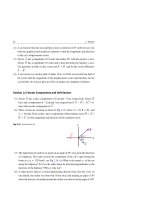
Except in vacuum, the index of refraction depends on the light’s wavelength, i.e. its
color, see Sect. 27.7. Therefore if a beam of light consists of rays of different wavelengths (as in the case of white light), each ray will refract by a different angle from
a surface. This spread of light is called chromatic dispersion, or simply dispersion.
Generally, the index of refraction n decreases with increasing wavelengths. This
means that the violet light (with wavelength λ 425 nm and index n = 1.3435) bends
more than the red light (with wavelength λ 700 nm and index n = 1.3318) when
passing through the interface between two materials. Figure 17.9a shows this for a
glass block, and Fig. 17.9b shows this for a glass prism.
The prism of Fig. 17.9b is more commonly used to observe color separation of
white light because the dispersion at the first surface is enhanced at the second
572
17 Light Waves and Optics
interface. Thus, the violet ray in the white light of Fig. 17.9b will emerge from the
right surface with an angle of deviation δV which is greater than the angle of deviation
δR of the red ray. The difference δV − δR is known as the angular dispersion, while
δY is the mean deviation of the yellow rays.
White light
A
Air
R
δR
V
Glass
R
δV
White light
V
Glass
(a)
(b)
Fig. 17.9 A schematic representation of the dispersion of white light. The violet color is bent more than
the red color. (a) Dispersion in a glass block. (b) Dispersion in a prism
The general expression of δ for any color turns out to be rather complicated.
However, as the angle of incidence decreases from a large value, the angle of deviation
δ is found to decrease at first and then increase. The angle of minimum deviation δm
is found when the ray passes through the prism symmetrically. This angle is related
to the angle of the prism A, and its index of refraction n by the relation:
n=
sin[(A + δm )/2]
sin(A/2)
−−−−−−−−−−→
When A is small
n=
A + δm
A
(17.12)
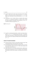
The most charming example of color dispersion is that of a rainbow. To understand
the formation of a rainbow we consider a horizontal overhead white sunlight that
is intercepted by spherical raindrops. Figure 17.10 shows refractions and reflection
in two raindrops that explain how light rays from the Sun reach an observer’s eye.
The first refraction separates the sunlight into its color components. Each color is
then reflected at the raindrop’s inner surface. Finally, a second refraction increases
the separation between colors, and these color rays finally make it to the observer’s
eye. Using Snell’s law and geometry, we find that the maximum deviation angles of
red and violet are about 42 and 40◦ , respectively. The rainbow that you can see is a
personal one because different observers receive light from different raindrops.
17.4 Chromatic Dispersion and Prisms
573
Raindrop
White light
Part of a rainbow
42°
White light
40°
ht
t lig
le
Vio
t
To
observer
d
Re
et
Viol
ligh
light
t
igh
l
ed
R
Fig. 17.10 A sketch of a rainbow formed by horizontal sunlight rays. Only two enlarged raindrops are
used to explain the rainbow’s formation for the case of the red and violet colors only
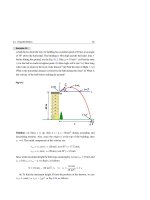
Example 17.4
A monochromatic light ray is incident from air (with index n1 = 1) onto an equilateral glass prism (with index n2 = 1.5) and is refracted parallel to one of its faces
(i.e. we have a symmetric ray), see Fig. 17.11. (a) What is the angle of incidence
θ1 at the first face? (b) What is the subsequent angle of incidence at the second
face? (c) Is the light ray totally reflected at the second face? If not, find the angle
of minimum deviation of the light ray. Then check that Eq. 17.12 holds.
Fig. 17.11
Air
q1
60°
q 2 q 1′
60°
Glass
dm
q 2′
60°
Solution: (a) The path of a symmetric light ray going through the prism (of apex
angle 60◦ ) and back out again into the air is shown.
Using elementary geometry, this figure shows that the angle of refraction θ2
can be found as follows:
θ2 + 60◦ = 90◦
Thus:
θ2 = 30◦
574
17 Light Waves and Optics
Therefore, using Snell’s law:
n1 sin θ1 = n2 sin θ2
We get:
θ1 = sin−1
= sin−1
n2 sin θ2
n1
1.5 × sin 30◦
1
= sin−1 (0.75) = 48.59◦
(b) Again, by simple geometry the horizontal light ray inside the prism must
be incident on the second face with an angle θ1 = θ2 = 30◦ .
(c) We know that if the incident angle is greater than the critical angle, then
total internal reflection must occur. Therefore, we first calculate the critical angle
as follows:
n1
n2
−1 1
= sin
1.5
−1
= sin 0.666
θc = sin−1
= 41.8◦
Since θ1 < θc , then the light ray refracts at the second face, and total internal
reflection will not occur.
Using the geometry shown in the figure, we can find for this special case that
the angle of minimum deviation is given by the following relation:
δm = 2(θ1 − θ2 )
= 2(48.59◦ − 30◦ )
= 37.18◦
Substituting A = 60◦ and δm = 37.18◦ in Eq. 17.12 gives:
sin[(A + δm )/2]
sin(A/2)
sin[(60◦ + 37.18◦ )/2]
=
sin(60◦ /2)
0.75
= 1.5
=
0.5
n2 =
17.4 Chromatic Dispersion and Prisms
575
This value of n2 obtained from Eq. 17.12 satisfies the given value of index of
refraction of the prism.
17.5
Formation of Images by Reflection
Mirrors gather and redirect light rays to form images of objects by reflection.
To explain this, we will use the ray approximation model in terms of geometric
optics, in which light travels in straight lines.
17.5.1 Plane Mirrors
A plane mirror is a plane surface that can reflect a beam of light in one direction
instead of either scattering it in many directions or absorbing it.
Figure 17.12a shows how a plane mirror can form an image of a point object O
located at a distance p from the mirror. In this figure, we consider two diverging rays
leaving O and strike the mirror and then are reflected to the eye of an observer. The
rays appear to diverge from point I behind the mirror. Thus, point I is the image of
point O. The geometry of the figure indicates that the image I is opposite to object
O and is located at a distance as far behind the mirror as the object is in front of the
mirror.
p
O
i
q
q
q
I
p
O
i
q
q
h′
h
q
I
q
q
Mirror
Mirror
Back side
Front side
(a)
Front side
Back side
(b)
Fig. 17.12 A geometric sketch that is used to depict an image of an object placed in front of a plane
mirror. (a) An image formed for a point object. (b) An image formed by an extended object, where the
object is an upright arrow of height h
576
17 Light Waves and Optics
Figure 17.12b shows how a plane mirror can form an image of an extended object
O. The object in this figure is an upright arrow of height h placed at a distance p from
the mirror. The full image can be inferred by locating the images of selected points
on the object. One of the two rays at the tip of the arrow follows a horizontal path
to the mirror and reflects back on itself. The second ray follows an oblique path and
reflects according to the laws of reflection, as shown in the figure. Using geometry
we find that the image I is upright, opposite to the object, and located behind the
mirror at a distance equal to the object’s distance in front of the mirror. In addition,
the height of the object and its image are equal. Also, the geometry of Fig. 17.12b
indicates that h /h = i/p.
The image I in both parts of Fig. 17.12 is called a virtual image because no light
rays pass through it. In addition, the value of i is considered to be negative since the
image is behind the mirror and the value of h is considered to be positive since the
image is upright.
We define the lateral magnification M of a horizontal overhead image as follows:
M=
h
Image height
=
Object height
h
(17.13)
We can use the relation h /h = i/p and the sign convention to write the lateral magnification M as follows:
M=
h
i
=−
h
p
(17.14)
For plane mirrors, M = 1, since h is positive and equal to h, or i is negative and has
a magnitude equal to p. The image formed by a plane mirror is upright but reversed.
The reversal of right and left is the reason why the word AMBULANCE is printed
as “
” across the front of ambulance vehicles. People driving in front
of such an ambulance can see the word “AMBULANCE” immediately evident when
looking in their rear-view mirrors and make way.
17.5.2 Spherical Mirrors
A spherical mirror is simply a mirror in the shape of a small section of the surface of
a sphere that has a center C and radius R. When light is reflected from the concave
17.5 Formation of Images by Reflection
577
surface of the mirror, the mirror is called a concave mirror. However, when light is
reflected from the convex surface of the mirror, the mirror is called a convex mirror.
Focal Point of a Spherical Mirror
The principal axis (or the symmetry axis) of a spherical mirror is defined as the
axis that passes through its center of curvature C and the center of the mirror c, see
Fig. 17.13. We consider the reflection of light coming from an infinitely far object
O located on the principal axis of a concave or convex spherical mirror. Because of
the great distance between the object and the mirror, the light rays reach the mirror
parallel to its principal axis.
Convex mirror
Concave mirror
Principal
axis
C
F
c
Principal
axis
F
C
c
Virtual focal point
Real focal point
Front side
f
R
Back side
f
Front side
R
Back side
(b)
(a)
Fig. 17.13 (a) Two parallel light rays will meet at a real focal point after reflecting from a concave
mirror. (b) The same rays will diverge from a convex mirror and appear to come from a virtual focal point
When parallel rays reach the surface of the concave mirror of Fig. 17.13a, they
will reflect and pass through a common point F. If we place a card at F, a point image
would appear at F. Therefore, this point is called the real focal point. However, in
the case of the convex mirror of Fig. 17.13b, the parallel rays reflect from the mirror
and appear to diverge from a common point F behind the mirror. If we could place
a card at F, no image would appear on the card. Therefore, this point is called the
virtual focal point. The distance f from the center of the mirror to the focal point
(real or virtual) is called the focal length of the mirror.
For concave and convex mirrors, the following relation relates the focal length f
to the radius of curvature R:
f =
R
2
(Spherical mirror)
(17.15)
578
17 Light Waves and Optics
17.5.2.1
Concave Mirrors
Sharp and Blurred Images
Rays that diverge from any point on an object and make small angles with the principal
axis (called paraxial rays) will reflect from the spherical concave mirror and intersect
at one image point. See Fig. 17.14a for a point object on the principal axis. On the
other hand, rays that diverge from the same point and make large angles with the
principal axis will reflect and intersect at different image points, see Fig. 17.14b. This
condition is called spherical aberration.
Small angles incidence
Large angles incidence
c
c
O
O
I
I1 I2
Sharp image
(a)
blurred image
(b)
Fig. 17.14 (a) When rays diverge from point object O at small angles with the principal axis, they all
reflect from the spherical concave mirror and meet at the same point image I. (b) When rays diverge
from O at large angles with the principal axis, they reflect from the spherical concave mirror and meet at
different points I1 , I2 , . . .
The Mirror Equation
The relationship between an object’s distance p, its image distance i, and the focal
length f of a concave mirror can be found when light rays make small angles with
the principal axis (paraxial rays). Figure 17.15a shows two rays (leaving an object O
of height h) reflected to form an image I of height h . The first ray strikes the mirror
at its center c and is reflected. The second ray passes through the focal point F and
reflects parallel to the principal axis.
From the purple triangles of Fig. 17.15a, we see that:
tan θ =
h
h
=
p
i
⇒
h
i
=
h
p
(17.16)
From the yellow triangles of Fig. 17.15b, we see that:
tan α =
h
h
=
p−f
f
⇒
h
f
=
h
p−f
(17.17)
17.5 Formation of Images by Reflection
O
579
O
Front
h
h′
q
F q
h
c
Front
a
h′
c
F
a
h′
h′
I
I
f
p
i
p
(a)
i
f
(b)
Fig. 17.15 (a) Intersection of two rays produced by a spherical concave mirror to form an image of the
tip of an arrow. (b) Demonstration of the geometry produced by only the second ray
By comparing Eqs. 17.16 and 17.17, we find that:
f
i
=
p
p−f
⇒
ip − if = pf
(17.18)
Dividing both sides of this equation by pif, we get:
1 1
1
+ =
p
i
f
(17.19)
Equation 17.19 is known as the mirror equation for spherical mirrors, and this
expression holds when we interchange p and i, i.e. when we can replace the object
O by the image I and vice versa. For a given value of f, we notice the following for
concave mirrors:
• When p > f , the image distance i is positive. A positive value of i means that the
image is real and inverted. See Fig. 17.16a,b for images smaller or larger than the
object.
• When p < f , the mirror equation is satisfied by a negative value of the image distance i. The negative image distance means that the image is virtual. When we
extend two rays from the object we find that the virtual image is upright and
enlarged, see Fig. 17.16d.
If we use this sign convention in the lateral magnification Eq. 17.13, then we can also
write M as follows:
M=
i
h
=−
h
p
(17.20)
We get an upright image for positive values of M and an inverted image for negative
values of M as shown in Fig. 17.16.
580
17 Light Waves and Optics
O
Front
Front
O
F
C
F
Real image
c
I
c
C
I
Real image
(a)
(b)
Front
O
O
c
C
(i = + ∞)
I
Front
c
F
C
Virtual
image
F
(c)
(d)
Fig. 17.16 (a) An object O outside the center of curvature C. (b) The object between the focal point F
and C. (c) The object at F. (d) The object inside the focal point F and its virtual upright image I
17.5.2.2 Convex Mirrors
Convex mirrors like those shown in Fig. 17.17 are called diverging mirrors. The
images formed by these types of mirrors are virtual because the reflected rays appear
to originate from an image behind the mirror. Furthermore, the images are always
upright and smaller than the object. Because of this feature, these types of mirrors
are often used in stores to prevent shoplifting.
Convex mirror
Virtual
image
O
Principal
axis
c
I F
Virtual focal point
f
Front side
C
R
Back side
Fig. 17.17 When the object O is in front of a convex mirror, the image is virtual, upright, and smaller
than the object
17.5 Formation of Images by Reflection
581
We can use Eqs. 17.19 and 17.20 for either concave or convex spherical mirrors
if we stick to the sign conventions presented in Table 17.2. This table gives the sign
conventions for the quantities f, i, h , and M.
Table 17.2 Sign conventions for spherical mirrorsa
Quantity
Symbol
Positive values when
Negative values when
Focal length
f
The mirror is concave
The mirror is convex
Image location
i
The image is in front of
The image is in behind the
mirror (real image)
mirror (virtual image)
Image height
h
The Image is upright
The Image is inverted
Magnification
M
The Image is upright
The Image is inverted
a
The object location p and its height h are both positive
Example 17.5
A concave mirror has a focal length of 10 cm. Locate and describe the image
formed by an object having distances: (a) p = 25 cm, (b) p = 15 cm, (c) p = 10 cm,
and (d) p = 5 cm.
Solution: Concave mirrors have a positive focal length, i.e. f = +10 cm. (a) To
find the image distance, we use Eq. 17.19 as follows:
1 1
1
1
1
1
1
1
1
+ =
⇒
+ =
⇒
=
−
p
i
f
25 cm
i
10 cm
i
10 cm 25 cm
1
25 cm − 10 cm
15
50
1
=
=
⇒ i=
cm
⇒
i
250 cm2
i
250 cm
3
The positive sign of i indicates that the image is real and located on the front
side of the mirror. The magnification of the image can be determined using
Eq. 17.20 as:
M=−
i
50/3 cm
=−
p
25 cm
⇒
M=−
2
3
The negative sign of M indicates that the image is inverted. In addition, the image
is reduced (66.7% of the size of the object) because the absolute value of M is
less than unity, see Fig. 17.16a.
(b) When p = 15 cm, the mirror and magnification equations give:
1
1
1
+ =
15 cm
i
10 cm
⇒
1
1
1
=
−
i
10 cm 15 cm
⇒
i = 30 cm
582
17 Light Waves and Optics
M=−
30 cm
i
=−
p
15 cm
⇒
M = −2
The image is real when i is positive, inverted when M is negative, and enlarged
when |M| > 1, see Fig. 17.16b.
(c) When p = 10 cm, the mirror equation gives:
1
1
1
+ =
10 cm
i
10 cm
⇒
i=∞
This means that the reflected rays are parallel to one another and formed at an
infinite distance from the mirror, see Fig. 17.16c.
(d) When p = 5 cm, the mirror and magnification equations give:
1
1
1
+ =
5 cm
i
10 cm
M=−
⇒
1
1
1
=
−
i
10 cm 5 cm
(−10 cm)
i
=−
p
5 cm
⇒
⇒
i = −10 cm
M = +2
The image is virtual (or behind the mirror) because i is negative, upright because
M is positive, and enlarged (twice as large) because M is greater than unity, see
Fig. 17.16d.
Example 17.6
An anti-shoplifter convex spherical mirror has a radius of curvature of 0.4 m.
Locate and describe the image formed by a man standing 3.8 m away from the
mirror.
Solution: The focal length of a mirror is half of its radius of curvature, but for a
convex mirror, the focal length that must be used in the mirror equation is:
f = −R/2 = −0.2 m
When f = −0.2 m and p = 3.8 m, the mirror and magnification equations give:
1 1
1
+ =
p
i
f
⇒
1
1
1
+ =−
3.8 m
i
0.2 m
1
1
1
=−
−
i
0.2 m 3.8 m
⇒
i = −0.19 m
17.5 Formation of Images by Reflection
M=−
583
(−0.19 m)
i
=−
p
3.8 m
⇒
M = +0.05
The image is virtual (or behind the mirror) because i is negative, upright because
M is positive, and reduced (5% of the man’s size) because M is less than unity.
17.6
Formation of Images by Refraction
Lenses gather and redirect light rays to form images of objects by refraction. Again,
we will use the ray-approximation model of geometric optics in which light travels
in straight lines to form images.
17.6.1 Spherical Refracting Surfaces
Consider two transparent media having indices of refraction n1 and n2 and the boundary between them is a spherical surface of radius R, see Fig. 17.18. Assume a point
object O exists in the medium with an index of refraction n1 . In addition, assume that
all rays make small angles with the principal axis (paraxial rays) when they leave O
and focus at point I after being refracted at the spherical surface.
Fig. 17.18 Geometry used to
derive Eq. 17.26 for n1 < n2
n1 < n2
θ2
n1
Front
q1
a
A
b
g
O
R
Back
I
C
p
n2
i
Applying Snell’s law on the single ray of Fig. 17.18 gives:
n1 sin θ1 = n2 sin θ2
(17.21)
Because θ1 and θ2 are assumed to be small angles, we use the small-angle approximation sin θ ≈ θ , where θ is measured in radians, to have:
n1 θ1 = n2 θ2
(17.22)
584
17 Light Waves and Optics
Next, we use the rule that an exterior angle of any triangle equals the sum of the two
opposite interior angles. Applying this rule to triangles OAC and AIC of Fig. 17.18,
we get:
θ1 = α + β and β = θ2 + γ
(17.23)
where α, β, and γ are also small angles. Eliminating θ1 and θ2 from the last two
equations gives:
n1 α + n2 γ = (n2 − n1 )β
(17.24)
From the figure we find that the following holds true for paraxial rays:
tan α ≈ α ≈
p
tan β ≈ β ≈
R
tan γ ≈ γ ≈
i
(17.25)
When substituting these expressions into Eq. 17.24 and eliminating h from the result,
we get the following relation:
n2
n2 − n1
n1
+
=
p
i
R
(17.26)
which is valid regardless of which index of refraction is greater. We notice that for
a fixed object distance p, the image distance i is independent of the small angle that
the paraxial ray makes with the axis. Therefore, we conclude that all paraxial rays
from point O focus at the same point I. The magnification is given by:
M=
n1 i
h
=−
h
n2 p
(17.27)
Again, we must use a sign convention if we want to apply Eq. 17.26 to a variety of
cases; see Table 17.3. We define the side of the surface in which light rays originate
as the front side. The other side is called the back side and is the side in which real
images are formed.
17.6.2 Flat Refracting Surfaces
When the refracting surface is flat, its radius of curvature R is infinite (i.e. R = ∞)
and Eq. 17.26 reduces to:
i=−
n2
p
n1
(17.28)
17.6 Formation of Images by Refraction
585
where the sign of i is opposite that of p. Thus, according to Table 17.3, the image
formed by a flat refracting surface is on the same side of the surface as the object,
see Fig. 17.19.
Table 17.3 Sign conventions for refracting surfacesa
Quantity
Positive values when
Negative values when
Radius
R
The center of curvature is
behind the surface
The center of curvature is in
front of the surface
Image location
i
The image is in behind the
surface (real image)
The image is in front of the
surface (virtual image)
Image height
h
The image is upright
The image is inverted
Magnification
M
The image is upright
The image is inverted
a
Symbol
When the object is in front of the surface, the object location p and its height h are positive.
Fig. 17.19 A virtual image
n1
formed by a flat refracting
surface when n1 > n2 . All rays
n2
Front
are assumed to be paraxial
Back
n1 > n 2
I
O
i
p
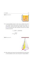
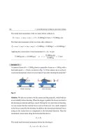
Example 17.7
A small fish is at a distance p below the water surface, see Fig. 17.20. The index
of refraction of water and air are n1 = 1.33 and n2 = 1, respectively. What is the
apparent depth of the fish as viewed by an observer directly above the water?
Fig. 17.20
n2 =1
i
p
n1 = 1.33
586
17 Light Waves and Optics
Solution: For flat refracting surfaces, we use Eq. 17.28 to find the location of the
image. Thus:
i=−
n2
1
p = −0.752 p
p=−
n1
1.33
The image of the fish is virtual because i is negative (both the object and image are
in front of the flat surface in water). The apparent depth of the fish is approximately
3/4 of the actual depth.
17.6.3 Thin Lenses
A lens is a transparent object with two refracting surfaces of different radii of curvature R1 and R2 but with a common principal axis, and when light rays bend across
these surfaces we get the image of an object.
When a lens converges light rays parallel to the principal axis, we call it a converging lens, see Fig. 17.21a. If instead it causes such rays to diverge, we call it a
diverging lens, see Fig. 17.21b.
Fig. 17.21 (a) An
(a)
enlargement of the top part of
a converging lens. (b) An
(b)
R2
R1
enlargement of the top part of
R1
R2
n
n
Converging lens
Diverging lens
a diverging lens
The Thin Lens Equation
First, we consider a thick glass lens bounded by two spherical surfaces, air-to-glass
and glass-to-air. This lens is defined by the radii R1 and R2 of the two surfaces, its
thickness , and its index of refraction n, see Fig. 17.22.
Let us begin with an object O placed at a distance p in front of surface 1 of radius
R1 . Using Eq. 17.26 with n1 = 1 and n2 = n, the position i1 of image I1 formed by
surface 1 satisfies the equation:
n
1
n−1
+ =
p i1
R1
(17.29)
17.6 Formation of Images by Refraction
R1
n1 = 1
O
p
R2
R1
R2
n
587
Real
image
I1 Virtual
image
n1 = 1
O
I1
C1
n
p
C1
p1
Δ
(a)
i1
i1
Δ
p1
(b)
Fig. 17.22 When we ignore the existence of surface 2 (of radius R2 ): (a) the first possibility is that an
object O produces a real image I1 by surface 1 (of radius R1 ), and (b) The other possibility is that the
image I1 is virtual. Point C1 is the center of curvature of surface 1
The position i1 is positive in Fig. 17.18a when the image I1 is real and negative in
Fig. 17.18b when the image I1 is virtual. In both cases, it seems as if I1 is formed in
the lens material with index n.
Next, we consider the image I1 as a virtual object placed at a distance p1 in front
of surface 2 of radius R2 . Again, applying Eq. 17.26 with n1 = n and n2 = 1, the
position i of the final image I formed by surface 2 satisfies the equation:
n
1
1−n
+ =
p1
i
R2
(17.30)
We note from Fig. 17.22a, b that p1 = −i1 + , where i1 is positive for real images and
negative for virtual objects. For thin lenses, is very small and therefore p1 − i1 .
Thus, the last equation becomes:
−
1−n
1
n
+ =
(For thin lenses)
i1
i
R2
(17.31)
Adding Eqs. 17.29 and 17.31, we get:
1
1 1
1
+ = (n − 1)
−
p
i
R1
R2
(17.32)
The focal length f of a thin lens is obtained when p → ∞ and i → f in this equation.
Thus, the inverse of the focal length for a thin lens is:
1
1
1
= (n − 1)
−
f
R1
R2
(17.33)
which is called the lens-makers’ equation because it can be used to determine R1
and R2 for the desired values of n and f.
588
17 Light Waves and Optics
In conclusion, a thin lens of index n and two surfaces of radii R1 and R2 has an
equation identical to the mirror equation, written as:
1 1
1
+ = , where
p
i
f
1
1
1
−
= (n − 1)
f
R1
R2
(17.34)
This is called the thin-lens equation. The sign conventions for R1 and R2 are presented in Table 17.3. Just as with mirrors, the thin lens lateral magnification is:
M=
i
h
=−
h
p
(17.35)
Since light rays can travel in both directions of a lens, then each lens has two focal
points F1 and F2 . Both focal points are at the same distance f (the focal length) from
a thin lens. The focal length f is the same for light rays passing through a given lens
in either direction. This is illustrated in Fig.17.23 for a biconvex lens (converging
lens) and a biconcave lens (diverging lens).
(b)
(a)
f
F1
f
F2 F1
f
f
F2
F1
F2
F1
F2
Fig. 17.23 Parallel rays passing through: (a) a converging lens, and (b) a diverging lens
Ray Diagrams for Thin Lenses
Ray diagrams are convenient tools that help us locate images formed by thin lenses.
They also clarify our sign conventions. For the purpose of locating an image, we
only use two special rays drawn from the top of the object to the top of the image as
follows:
• Ray 1 starts parallel to the principal axis.
– For a converging lens, the ray is refracted by the lens and passes through the
focal point F2 on the back side of the lens.
– For a diverging lens, the ray is refracted by the lens and appears to originate
from the focal point F1 on the front side of the lens.
17.6 Formation of Images by Refraction
589
• Ray 2 passes through the center of the lens and continues in a straight line.
Figure 17.24 shows such ray diagrams for converging and diverging lenses.
F2
O
I
F1
I
F1 O
Back
Front
F2
Back
Front
(a)
(b)
O
F1
F2
I
Front
Back
(c)
Fig. 17.24 Ray diagrams for locating the image formed by a thin lens. (a) An object in front of a
converging lens (double convex lens). When the object is outside the focal point, the image is real, inverted,
and on the back side of the lens. (b) When the object is between the focal point and the converging lens
(double convex lens), the image is virtual, upright, larger than the object, and on the front side of the lens.
(c) When an object is anywhere in front of a diverging lens (double concave lens), the image is virtual,
upright, smaller than the object, and on the front side of the lens
When using Eq. 17.34, it is very important to use the proper sign conventions
introduced in Table 17.4.
Table 17.4 Sign conventions for thin lenses
Quantity
Symbol
Positive values when
Negative values when
Radii
R1 or R2
The center of curvature is in
back of lens
The center of curvature is in
front of the lens
Object location
p
The object is in front of lens
(real object)
The object is in back of lens
(virtual object)
Image location
i
The image is in back of lens
(real image)
The image is in front of lens
(virtual image)
Image height
h
The Image is upright
The Image is inverted
Magnification
M
The Image is upright
The Image is inverted
Table 17.5 shows a comparison of the image positions, magnifications, and types
of images formed by convex and concave lenses when an object is placed at various
590
17 Light Waves and Optics
positions, p, relative to the lens. Notice that a converging (biconvex lens) can produce
real images or virtual images, whereas a diverging (biconcave) lens only produces
virtual images.
Table 17.5 Properties of a single spherical lens system
Type of lens
Converging lens
(Biconvex lens)
Diverging lens
(Biconcave lens)
∗
f
+
−
p
i
M
Image
p>2 f
2 f >i>f
Real
2 f >p>f
i>2 f
f >p>0
|i| > p
(Negative)
Reduced
inverted
Enlarged
inverted
Enlarged
upright
p>0
|f | > |i| > 0
(Negative)
Reduced
upright
Real
Virtual
Virtual
Combination of Thin Lenses
To understand and locate the image produced by two lenses, we follow two steps.
The first image formed by the first lens is located as if the second lens were not
present. Then this first image is treated as a virtual object and we use the second lens
to find the final image. This procedure can be extended to three or more lenses.
Let us consider the case were two lenses of focal lengths f1 and f2 are in contact
with each other. If p is the object distance from the system and i1 the is image distance
produced by the first lens, then:
1
1
1
+ =
p i1
f1
and
M1 = −
i1
p
(17.36)
(17.37)
This image is the object for the second lens. Since this image is behind the second
lens, it serves as a virtual object and its distance for the second lens is negative, i.e.
its distance to the second lens is −i1 (see Table 17.4). Therefore, the distance i of the
final image produced by the second lens satisfies:
−
and
1
1
1
+ =
i1
i
f2
M2 = −
i
i
=
(−i1 )
i1
(17.38)
(17.39)