Hafez a radi, john o rasmussen auth principles of physics for scientists and engineers 2 25
Bạn đang xem bản rút gọn của tài liệu. Xem và tải ngay bản đầy đủ của tài liệu tại đây (942.78 KB, 30 trang )
17.6 Formation of Images by Refraction
591
Adding the two Eqs. 17.36 and 17.38 gives:
1
1 1
+ = , where
p
i
f
1
1
1
= +
f
f1
f2
(17.40)
Thus, two thin lenses in contact are equivalent to a single thin lens of focal length f
given by f −1 = f1−1 + f2−1 . The overall magnification of the two lenses is:
i1 i
i
(Thin lenses in contact)
=−
p i1
p
M = M1 M2 = −
(17.41)
Example 17.8
A converging lens of focal length 20 cm forms an image of an object of height
30 cm located at a distance 40 cm from the lens. Locate and describe the image.
Draw two rays to locate the image.
Solution: A converging lens has a positive value for its focal length, i.e.
f = +20 cm. To find the image distance when p = 40 cm and f = +20 cm, we
use Eq. 17.34 as follows:
1 1
1
+ =
p
i
f
⇒
Consequently we have :
1
1
1
+ =
⇒ i = 40 cm
40 cm
i
20 cm
40 cm
i
⇒ M = −1
M=− =−
p
40 cm
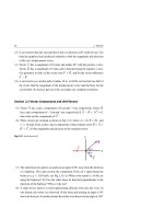
The image is real and on the back side because i is positive, inverted because M
is negative, and as large as the object, see Fig. 17.25.
Fig. 17.25
1
2
O
C1
F2
F1
I
Back
Front
Example 17.9
Repeat Example 17.8 using a diverging lens.
Solution: The diverging lens would have f = −20 cm. Thus:
1 1 1
+ =
p
i f
⇒
1
1
1
+ =−
40 cm
i
20 cm
C2
⇒
i = −40/3 cm
592
17 Light Waves and Optics
Consequently, we have: M = −
(−40/3 cm)
i
=−
p
40 cm
⇒
M = +1/3
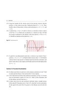
The image is virtual and on the front side because i is negative, upright because
M is positive, and reduced because M is less than unity, see Fig. 17.26.
Fig. 17.26
1
2
O
C1
F1
F2
I
Front
Back
Example 17.10
An object is placed 20 cm from a symmetrical lens that has an index of refraction n = 1.65. The lateral magnification of the object produced by the lens is
M = −1/4. (a) Determine the type of the lens and describe the image. (b) What
is the magnitude of the two radii of curvature of the lens?
Solution: (a) Using the lateral-magnification equation, we have:
M=−
i
1
=−
p
4
⇒
i=
p
20 cm
=
4
4
⇒
i = +5 cm
Because i is positive, the obtained image must be real. The only type of lens that
can produce a real image is a converging lens. According to Fig. 17.24a, the object
must be outside the focal point and the image must be inverted and on the back
side of the lens.
(b) To find the focal length f of the lens when p = 20 cm and i = +5 cm, we
use Eq. 17.34 as follows:
1 1
1
+ =
p
i
f
⇒
1
1
1
+
=
20 cm 5 cm
f
⇒
f = 4 cm
From the general lens-makers’ Eq. 17.33, f is related to the radii of curvatures R1
and R2 of the two surfaces of the lens and its index of refraction n by the relation:
1
1
1
= (n − 1)
−
f
R1
R2
17.6 Formation of Images by Refraction
593
For a symmetric lens, R1 and R2 have the same magnitude R. If R1 is for the
surface where the center of curvature is in the back of the lens, and R2 is for the
surface where the center of curvature is in the back of the lens, then using the sign
convention of Table 17.4, we have R1 = +R and R2 = −R. Thus:
1
1
1
= (n − 1)
−
f
R −R
Hence,
=
2(n − 1)
R
⇒
R = 2(n − 1) f ,
R = 2(n − 1) f = 2(1.65 − 1) × (4 cm) = 5.2 cm
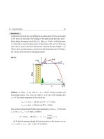
Example 17.11
Two thin coaxial lenses 1 and 2, with focal lengths f1 = +24 cm and f2 = +9 cm,
respectively, are separated by a distance L = 10 cm; see part (a) of Fig. 17.27. An
object is placed 6 cm in front of lens 1. Locate and describe the image. Draw the
necessary sketches to show how you can reach to the answer.
Solution: We first ignore the presence of lens 2 and find the image I1 produced
by lens 1 alone, see part (b) Fig. 17.27. Equation 17.34 written for lens 1 leads to
the following steps:
1
1
1
+ =
p i1
f1
⇒
1
1
1
+ =
6 cm i1
24 cm
i1 = −8 cm
Consequently, we have the following lateral magnification:
M1 = −
(−8 cm)
i1
=−
p
6 cm
⇒
M1 = +4/3
This tells us that image I1 is virtual (8 cm in front of lens 1), upright because M is
positive, and enlarged because M is greater than unity, see part (b) of Fig. 17.27.
For the second step, we ignore lens 1 and treat the image I1 as a virtual object
O1 in front of the second lens. The distance p1 between the virtual object O1 and
lens 2 is:
p1 = L − i1 = 10 cm − (−8 cm) = 18 cm
Equation 17.34 written for lens 2 leads us to the following:
594
17 Light Waves and Optics
Lens 1
Lens 2
O
(a)
p
L
Lens 1
Front Back
F1
I1
O
F1
(b)
p
f1
L
i1
Lens 2
Back
Front
O1
F2
F2
(c)
I
f2
p1 = L+ |i1|
i
Fig. 17.27
1
1
1
+ =
p1
i
f2
⇒
1
1
1
+ =
18 cm
i
9 cm
i = +18 cm
Consequently, we have the following lateral magnification:
M2 = −
i
18 cm
=−
p1
18 cm
⇒
M2 = −1
17.6 Formation of Images by Refraction
595
The final image is real because i is positive and on the back side of lens 2, inverted
because M is negative, and as large as the virtual object I1 , see part (c) of Fig. 17.27.
The overall magnification of the two lenses is:
M = M1 M2 =
i1 i
(−8 cm) (18 cm)
=
p p1
(6 cm) (18 cm)
M = −4/3
The final image is enlarged because |M| > 1. Notice that when L = 0, we get
M = −i/p as expected from Eq. 17.41.
17.7
Exercises
Section 17.2 Reflection and Refraction of Light
(1) A beam of light travels in vacuum and has a wavelength λ = 500 nm. The beam
passes through a piece of diamond (n = 2.4). What is the wave’s speed and
wavelength in diamond?
(2) Assume that the wavelength of a yellow beam of light in vacuum is λ = 600 nm,
and that the index of refraction of water is 1.33. (a) What is the speed of this light
when it travels in vacuum? (b) What is the speed of this light when it travels
in water? (c) What is the frequency of this light when it travels in vacuum?
(d) What is the wavelength of this light when it travels in water? (e) What is
the frequency of this light when it travels in water?
(3) A beam of light having a wavelength λ = 600 nm is incident perpendicular to a
glass plate of thickness d = 2 cm and index of refraction n = 1.5. (a) How long
does it take a point on the beam to pass through the plate? (b) Calculate the
number of wavelengths in the glass plate.
(4) At what angle must a ray of light traveling in air be incident on acetone
(n = 1.38) in order to be refracted at 30◦ ?
(5) The index of refraction of alcohol is n = 1.4. (a) What is the speed of light in
alcohol? (b) Find the angle of refraction in alcohol assuming light meets the
air-alcohol boundary at an angle of incidence of 60◦ ?
(6) A beam of light in air falls on a liquid surface at an angle of incidence of 55◦ .
The liquid has an unknown index of refraction. (a) If the beam is deviated by
20◦ , what is the value of n? (b) What is the speed of light in this liquid?
596
17 Light Waves and Optics
(7) A beam of light in air strikes a glass plate at an angle of incidence of 53◦ . If
the thickness of the glass plate is 2 cm and its index of refraction is 1.6, what
will be the lateral displacement of the beam after it emerges from the glass?
(8) A beam of light in air falls on water at an angle of incidence of 45◦ and then
passes through a glass block before it emerges out to air again. The surfaces
of water and glass are parallel and their indexes of refraction are 1.33 and
1.63, respectively. (a) What is the angle of refraction in water? (b) What is the
angle of refraction in glass? (c) Show that the incoming and outgoing beams
are parallel. (d) At what distance does the beam shift from the original if the
thickness of water and glass are both equal to 1 cm?
Section 17.3 Total Internal Reflection and Optical Fibers
(9) Diamond has a high index of refraction n = 2.42. To some extent, Diamond’s
“brilliance” is attributed to its total internal reflection. Find the critical angle
for the diamond-air surface.
(10) A beam of light passes from glass to water. The index of refraction of glass
and water are 1.52 and 1.333, respectively. (a) What is the critical angle of
incidence in glass? (b) If the angle of incidence in glass is 45◦ , what is the
angle of refraction in water?
(11) As it travels through ice, light has a speed of 2.307 × 10⁸ m/s. (a) What is the
index of refraction of ice? (b) What is the critical angle of incidence for light
going from ice to air? (c) If the angle of incidence in ice is 45◦, what is the
angle of refraction in air?
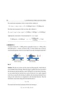
(12) As the sun sets, its rays are nearly tangent to the surface of water, see Fig. 17.28.
The index of refraction of water is 1.33. (a) At which angle from the normal
would the fish in the figure see the sun? (b) Refraction at the water-air boundary
changes the apparent position of the Sun. What is the apparent direction of the
Sun with respect to the fish (measured above the horizontal)?
(13) Figure 17.29 shows a sketch of an Optical fiber cable that has a length
L = 1.51 m, diameter of D = 251 µm, and index of refraction n = 1.3. A ray
of light is incident on the left end of the cable at an angle of incidence θ1 = 45◦ .
(a) What is the critical angle of incidence for light going from inside the cable
to air? (b) Find the angle of refraction θ2 and the length . Does the angle θ
17.7 Exercises
597
fulfill the condition of total internal reflection? (c) How many reflections does
the light ray make before emerging from the other end?
Direction of the sun
as seen by the fish
Fig. 17.28 See Exercise (12)
Apperant
position
Air n 2 =1
Sun
Water
n1 = 1.33
L
Air
n1= 1
θ
θ2
Optical fiber
n 2 = 1.3
D
θ1
Fig. 17.29 See Exercise (13)
(14) Using the figure of Exercise 13, show that the largest angle of incidence θ1
for which total internal reflection occuring at the top surface is given by the
relation sin θ1 = (n2 /n1 )2 − 1. Now find the value of this angle using the data
of Exercise 13.
Section 17.4 Chromatic Dispersion and Prisms
(15) Find the difference in time needed for two short pulses of light to travel 12 km
through a fiber optics cable, assuming that the cable’s index of refraction for a
pulse of wavelength 700 nm is 1.5 and 1.53 for a pulse of wavelength 400 nm.
(16) A monochromatic light ray is incident from air (n1 = 1) onto one of the faces
of an equilateral prism that has an index of refraction n2 = 1.5, see Fig. 17.30.
If the angle of incidence θ1 is 40◦ , then at what angle from the normal would
this ray leave the prism?
598
17 Light Waves and Optics
Fig. 17.30 See Exercise (16)
Air n1
60°
Glass n 2
θ1
θ2
θ4
θ3
120°
60°
60°
(17) A narrow beam of white light is incident from air onto a plate of fused quartz
at an angle of incidence θ1 = 60◦ ; see Fig. 17.31. The index of refraction of
quartz for violet and red light is nV = 1.470 and nR = 1.458, respectively. Find
the angular width δV −δR between the violet and red light rays inside the quartz.
Fig. 17.31 See Exercise (17)
White light
θ1
Air
R δR
Quartz
V
δV
(18) A prism has an index of refraction n = 1.5 and an apex angle A = 30◦ . The
prism is set for minimum deviation by allowing a ray of monochromatic light
to pass through it symmetrically, as shown in Fig. 17.32. (a) Find the angle of
minimum deviation δm . (b) Find the value of the angle of incidence θ1 .
Fig. 17.32 See Exercise (18)
Air
30°
δm
θ1
Glass
17.7 Exercises
599
Section 17.5 Formation of Images by Reflection
(19) The height h of a man is 200 cm. The top of his hat t, his eyes e, and his feet
f are marked by dots on Fig. 17.33. In order for the man to be able to see his
entire length in a vertical plane mirror, he needs a mirror of height H, as shown.
The figure also shows two paths, one for the light ray leaving his hat t and
entering his eyes e, and another for the light ray leaving his feet f and again
entering his eyes e. (a) Find the height H of the mirror. (b) Use two rays to
make a geometric sketch for the location and the height of the man’s image.
Fig. 17.33 See Exercise (19)
t
a
b
e
H
Mirror
h
c
f
p
(20) A concave mirror has a radius of curvature of 1.5 m. Where is the focal point
of this mirror?
(21) A concave mirror has a focal length f = +0.2 m. An object of height 3 cm is
placed 0.1 m along its principal axis. Locate and describe the image formed by
the mirror.
(22) Repeat Exercise 21 using a convex mirror.
(23) Assume a spherical concave mirror has a positive focal length | f |. Use the
mirror equation 1/p + 1/i = 1/| f | to determine where an object must be placed
if the image created has the same size as the object, i.e. when M = | − i/p| = 1.
(24) Assume a spherical convex mirror has a negative focal length −| f |. Use the
mirror equation 1/p + 1/i = −1/| f | to show that the condition M = |−i/p| = 1
cannot not be satisfied.
600
17 Light Waves and Optics
(25) Six objects are located at the following positions from a spherical mirror:
(i) p = ∞, (ii) p = 15 cm, (iii) p = 10 cm, (iv) p = 7.5 cm, (v) p = 5 cm,
and (vi) p = 2.5 cm. Locate and describe the image for each object when the
spherical mirror is: (a) concave, with a focal length of 5 cm, (b) convex, with a
focal length of 5 cm.
(26) Repeat Exercise 25, this time sketching the lateral magnification M for each
object’s location p.
Section 17.6 Formation of Images by Refraction
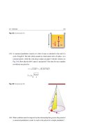
(27) (a) A cylindrical glass rod (n2 = 1.6) has a hemispherical end of radius
R = 2 cm. An object of height h = 0.2 cm is placed in air (n1 = 1) on the axis
of the rod at a distance p = 6 cm from the spherical vertex, see Fig. 17.34.
(a) Locate and describe the image. (b) Repeat part (a) when p = 2 cm.
Fig. 17.34 See Exercise (27)
n 1 =1
n1 < n2
n 2 =1.5
Back
h
Front O
I
h'
C
p
R
i
(28) A spherical fish bowl filled with water (n1 = 1.33) has a radius of 15 cm.
A small fish is located at a horizontal distance p = 20 cm from the left side
of the bowl, see Fig. 17.35. Neglecting the effect of the glass walls of the bowl,
where does an observer see the fish’s image? What is the lateral magnification
of the fish?
Fig. 17.35 See Exercise (28)
n2 = 1
i
O
Back
Front
I
p
n1
1.33
17.7 Exercises
601
(29) (a) An object is placed 30 cm from a converging lens with a 10 cm focal length.
Find the position of the image and its lateral magnification. Is the image real or
virtual? Is it upright or inverted? (b) Repeat part (a) for an object placed 5 cm
away.
(30) Repeat Exercise 29 with a diverting lens.
(31) Use a ray diagram to explain the results of Exercises 29 and 30.
(32) An object is placed 20 cm from a symmetrical lens that has an index of refraction n = 1.6. The lateral magnification of the object produced by the lens is
M = 1/4. (a) Determine the type of the lens used and describe the image.
(b) What are the values of the two radii of curvature of the lens?
(33) A thin converging lens of focal lens f1 = +15 cm is placed in contact with a
thin diverging lens of unknown focal length f2 . Find f2 when incident Sunrays
on the converging lens are focused by this combination at a point 25 cm behind
the diverging lens.
(34) A converging lens of focal lens f1 = +2 cm is placed at a distance L = 4 cm
in front of a diverging lens of focal lens f2 = −14 cm. An object is placed at
infinite distance from the converging lens. Where will the object be focused?
(35) Repeat Exercise 34 with f1 = +10 cm and f2 = −16 cm.
(36) Two lenses with focal lenses f1 = +16 cm and f2 = +20 cm are at a distance
L = 64 cm apart. An object is placed 48 cm in front of the first lens. Locate and
describe the image formed by the system.
(37) Repeat Exercise 36 with L = 19 cm.
(38) A converging lens of f2 = +17 cm is placed behind a diverging lens of unknown
focal lens f1 by a distance L = 12 cm. Find f1 when parallel light rays strike the
diverging lens and leave the converging lens parallel.
(39) Repeat Exercise 38 when the two lenses exchange positions.
(40) An object is moving with velocity v = −dp/dt toward a converging lens of
focal length f such that p > f . Find the image velocity di/dt as a function of p.
Find p when v = di/dt.
Interference, Diffraction
and Polarization of Light
18
In this chapter we treat light as waves to study interference, diffraction, and polarization. This study is known as wave optics or physical optics.
We found in Chap. 16 that the superposition of two sound waves could be constructive or destructive. The same phenomena can be observed with light waves.
When a resultant wave at a given position or time has an amplitude larger than
the individual waves, we refer to their superposition as constructive interference.
However, when a resultant wave has an amplitude smaller than the individual waves,
we refer to their superposition as destructive interference.
18.1
Interference of Light Waves
If you have two ordinary light bulbs, incandescent or fluorescent, the light waves they
emit have random phases. These phases change in time intervals that are less than a
nanosecond apart; thus, the conditions for constructive and destructive interference
are maintained for only very short time intervals, too short for our eyes to notice.
Such light sources are said to be incoherent.
Spotlight
To observe detailed interference effects in light waves, the following conditions
must be fulfilled:
• The sources must be coherent, i.e., they must maintain a constant phase
with respect to each other.
• The sources must be monochromatic, i.e., of a single wavelength.
H. A. Radi and J. O. Rasmussen, Principles of Physics,
Undergraduate Lecture Notes in Physics, DOI: 10.1007/978-3-642-23026-4_18,
© Springer-Verlag Berlin Heidelberg 2013
603
604
18 Interference, Diffraction and Polarization of Light
A common method for observing interference is to allow a single monochromatic
light source to split to form two coherent light sources and then allow the light waves
from the two sources to overlap. This can be achieved by using the diffraction of
light waves from a small opening as introduced in Fig. 17.2. Figure 18.1 shows the
overlap of monochromatic coherent light waves after being diffracted from two slits
when λ ≈ a, where a is the width of each slit.
Fig. 18.1 Spreading of light
a
waves from each slit (which is
known as diffraction) ensures
overlapping of waves, and
hence interference effects can
a
be observed when the light
from the two slits arrive at a
viewing screen (which is not
shown in this figure)
a
Ray
Wave Fronts
18.2
Young’s Double Slit Experiment
Figure 18.2 shows a schematic diagram of the apparatus used by Thomas Young
in 1801 to demonstrate the interference of light waves. Plane monochromatic light
waves arrive at a barrier that has two parallel slits S1 and S2 . These two slits serve as
a pair of coherent light sources because the emerging waves originate from the same
wave front and hence have the same phase relationship.
Diffraction of the light by the two slits sends overlapping waves into the region
between the barrier and the viewing screen. When light waves from the two slits
combine constructively at any location on the screen, they produce a bright band.
On the other hand, when light from the two slits combine destructively at any location
on the screen they produce a dark band. These bands are called fringes, and the
pattern of bright and dark fringes is called an interference pattern. Figure 18.2b
shows a representation of the interference pattern observed on the screen.
18.2 Young’s Double Slit Experiment
Wave fronts from S1
Wave fronts from S 2
λ
605
Min
Max
Min
S1
Max
S2
Min
Max
Wave Fronts
Barrier
Min
Screen
(a)
(b)
Fig. 18.2 (a) When light waves are diffracted from the two slits S1 and S2 , waves overlap and undergo
interference. Constructive interference in the region between the barrier and screen is represented by red
circles on the red lines. Destructive interference is represented by the yellow lines. (b) Representation of
the photograph that we get for the interference pattern in Young’s double slit experiment
With the help of Fig. 18.3a, we can quantitatively specify the positions of bright
and dark fringes in Young’s experiment. In this figure, we show the following:
• Light waves of wavelength λ illuminating a barrier having two narrow slits
• The two slits S1 and S2 are separated by a distance d
• Point Q is half way between the two slits
• The central line QO between the barrier and the screen has a distance D (where
D
d)
• Point P on the screen makes an angle θ above the central line QO. The central line
QO will be taken as a reference line for measuring positive angles above or below
the line
• The distance from P to S1 is r1 , and the distance from P to S2 is r2 .
The waves from S2 must travel a longer distance to reach point P than the waves
starting at S1 . This difference L in distance is called the path difference. When
606
18 Interference, Diffraction and Polarization of Light
θ
S1
d
S2
Wave Fronts
y
S1
r2
θ
Q
O
d
ΔL
S2
D
Screen
Barrier
≈∞
r1
P
r1
(a)
r2
θ
≈∞
Δ L = d sinθ
(b)
Fig. 18.3 (a) Locating the fringes for Young’s double slit experiment geometrically (the figure is not
to scale). (b) For the condition D
d, we can approximate rays r1 and r2 as being parallel, making an
angle θ to the central line QO, and the path difference between the two rays is r2 − r1 = d sin θ
D
d, the rays r1 and r2 are approximately parallel. Using Fig. 18.3b the path
difference will be:
L = |r2 − r1 |
d sin θ
(18.1)
Constructive interference (maximum light intensity) occurs at P when the two waves
are in phase (φ = 0, ±2π, ±4π, . . . rad), or when the path difference d sin θ is an
integer multiple of the wavelength λ. That is, when:
d sin θm = m λ
(m = 0, 1, 2, . . .)
Maxima
Bright fringes
(18.2)
The number m for a bright fringe is called the fringe order number. The central
bright fringe at θm = 0, where m = 0, is called the zeroth-order maximum. The first
maximum on either sides of point O, where m = 1, is called the first-order maximum,
and so forth.
Destructive interference occurs at P when the path difference d sin θ is an odd
multiple of half the wavelength. That is when:
d sin θm = (m − 21 ) λ
(m = 1, 2, 3, . . .)
Minima
Dark fringes
(18.3)
Similarly, the two waves reaching P at any time are completely out-of-phase
(φ = ±π, ±3π, ±5π, . . . rad), and hence a minimum light intensity is detected.
In this case, the first minimum on either side of point O, where m = 1, is called
the first-order minimum, and so forth.
18.2 Young’s Double Slit Experiment
607
Using the triangle OPQ of Fig. 18.3a, we can find the location y, on either side
of point O, of a fringe from the relation:
y = D tan θ
(18.4)
In addition to the conditions λ a (where a is the width of each slit) and D d,
we assume that λ d. This assumption is valid only if θ is very small and hence
tan θ
sin θ. Therefore, y = D sin θ, or:
Bright or dark fringes
ym = D sin θm
when θm is very small
(18.5)
Substituting with sin θm into Eqs. 18.2 and 18.3, we get the following expressions
for the locations of bright and dark fringes above or below the central point O:
ym = m
λD
(m = 0, 1, 2, . . .)
d
ym = (m − 21 )
Bright fringes
for very small angles
λD
(m = 1, 2, 3, . . .)
d
Dark fringes
for very small angles
(18.6)
(18.7)
We can find the distance on the screen between the adjacent maxima or minima
near the origin O by finding the difference:
y = ym+1 − ym
Bright or dark
fringes
(18.8)
Using Eq. 18.6, for bright fringes, we find:
y = ym+1 − ym = (m + 1)
λD
λD
−m
d
d
Therefore:
y=
λD
d
Above or below the central
point for very small angles
(18.9)
In other words, when the condition for small-angle approximation is valid, y does
not depend on the order of the fringe m and the fringes are uniformly spaced. The
same result is true for dark fringes.
608
18 Interference, Diffraction and Polarization of Light
Example 18.1
Two narrow slits are separated by 0.06 mm and are 1.2 m away from a screen.
When the slits are illuminated by light of unknown wavelength λ, we obtain a
fourth-order bright fringe 4.5 cm from the central line. Find the wavelength of the
light.
Solution: Using Eq. 18.6, with m = 4 and λ
ym = m
Thus: λ =
λD
d
⇒
λ=
d, we find that:
d ym
mD
⇒
λ=
d y4
4D
(0.06 × 10⁻³ m)(4.5 × 10⁻² m)
= 5.625 × 10⁻⁷ m = 563 nm
4 × 1.2 m
This wavelength is in the range of green light. The angle that this fringe makes
with the central line is θ4 = tan−1 (y4 /D) = 2.15◦ .
Example 18.2
Two narrow slits are separated by 1.5 mm and are 3 m away from a screen. The
slits are illuminated by a yellow light of wavelength 589 nm from a sodium-vapor
lamp. Find the spacing between the bright fringes.
Solution: Using Eq. 18.9 when λ
y = ym+1 − ym =
d, we have:
λ D (589 × 10−9 m)(3 m)
=
= 1.178 × 10⁻³ m = 1.178 mm
d
1.5 × 10⁻³ m
Example 18.3
Two slits are separated by 0.4 mm and illuminated by light of wavelength 442 nm.
How far must the screen be placed in order for the first dark fringes to appear
directly opposite both slits?
Solution: Taking m = 1, d = 0.4 mm, y1 = 0.2 mm, and λ = 442 nm in Eq. 18.7,
see Fig. 18.4 , we get:
ym = (m − 21 )
λD
d
⇒
D=
2 d y1
λ
18.2 Young’s Double Slit Experiment
D=
609
2(4 × 10⁻⁴ m)(2 × 10⁻⁴ m)
= 0.36 m = 36 cm
442 × 10−9 m
Geometric optics incorrectly predicts bright regions opposite the slits.
Fig. 18.4
Bright
Dark
S1
d
y1
o
y1
Bright
Dark
S2
D
Bright
Light Intensity in the Double-Slit Experiment
Let us assume that the waves emerging from the two slits of Fig. 18.3a are two
sinusoidal electric fields having the same phase, wavelength λ, angular frequency
ω = 2π f , and amplitude E◦ . When the two waves arrive at point P, their phase
difference φ depends on the path difference L = |r2 − r1 | d sin θ. We can write
the magnitude of the electric field at point P due to each separate wave as:
E1 = E◦ sin(ω t),
(18.10)
E2 = E◦ sin(ω t + φ)
The superposition of E1 and E2 , E = E1 + E2 , can be calculated in a similar way as
in Sect. 16.6. Thus:
E = 2 E◦ cos
φ
2
sin ω t +
φ
2
(18.11)
We can prove that the intensity I of light waves at P is proportional to the square of
the resultant electric field averaged over one cycle. Thus:
I = I◦ cos2
φ
2
,
I◦ = 4 Imax
(18.12)
where I◦ is the peak intensity and Imax is the maximum intensity of one slit when the
second slit is closed.
Since a path difference of a complete wave length λ corresponds to a phase
difference of 2π rad, then one can relate the path difference L to the phase difference
φ or vice-versa by the two relations:
610
18 Interference, Diffraction and Polarization of Light
φ ⎫
λ⎪
⎪
⎪
2π ⎬
or
⎪
⎪
2π
⎪
L⎭
φ=
λ
L=
In the last form, when we replace
the phase:
(18.13)
L by d sin θ, we get the following relation for
2π d
sin θ
λ
φ=
In addition, when we use the condition sin θ
(18.14)
tan θ, and replace tan θ by y/D as
shown in Fig. 18.3, we arrive at the following relation for the phase:
2π d
y
λD
φ
(18.15)
Substituting the expression of φ from Eqs. 18.14 and 18.15 into Eq. 18.12, we get:
I = I◦ cos2
I
I◦ cos2
πd
sin θ
λ
(18.16)
πd
y
λD
(18.17)
Constructive interference occurs when π d y/λ D is an integer multiple of π,
corresponding to ym = m λ D/d, (m = 0, 1, 2, . . .). This is consistent with Eq. 18.6.
Figure 18.5 shows the variation of the intensity I against both d sin θ and φ, when
we satisfy both the conditions D
d and the small observation angle.
Below the origin
o
I
Above the origin o
I°
2λ
λ
0
λ
2λ
4π
2π
0
2π
4π
d sin θ
φ
Fig. 18.5 A sketch showing intensity variations of a double-slit interference pattern as a function of the
path difference
values of θ
L = d sin θ or the phase difference φ. This variation limit is true only for very small
18.3 Thin Films—Change of Phase Due to Reflection
18.3
611
Thin Films—Change of Phase Due to Reflection
We saw that path differences can be used to generate a phase difference as given by
Eq. 18.13. Reflection is another method that we can use to generate a phase difference
for electromagnetic waves (especially light waves). Specifically, the reflection of light
from surfaces has the following effects:
• When a light wave traveling in a homogenous medium meets a boundary of higher
index of refraction, it reflects, undergoing a phase change of π rad ( = 180◦ ).
• When a light wave traveling in a homogenous medium meets a boundary of lower
index of refraction, it reflects, undergoing no phase change.
These two rules can be deduced from Maxwell’s equations, but the treatment is
beyond the scope of this text. Fig. 18.6 summarizes these two rules.
π phase change due to reflection
Air n1 = 1
Almost normal incidence
1
Exaggerated scale
2
n2 = n > 1
d
Air n3 = 1
3
4
No phase change
due to reflection
Fig. 18.6 When n1 < n2 , light traveling in medium 1 will reflect from the surface between media 1 and 2
with 180◦ phase change. When n2 > n3 , light traveling in medium 2 will reflect from the surface between
media 2 and 3 with no phase change. Rays 1 and 2 lead to interference of the reflected light, while rays 3
and 4 lead to interference of the transmitted light. All rays are drawn not quite normal to the surface, so
we can see each of them
The incoming ray in Fig. 18.6 is a light ray of wavelength λ that almost normally
strikes a thin transparent film of thickness d. This ray is reflected from the upper
surface of the film as ray 1 and has experienced a phase change φ1 = π rad relative to
the incident wave because n1 < n2 . The transmitted ray has a wavelength λn = λ/n
and undergoes a second reflection at the lower surface without a phase change because
n2 > n3 . This ray is transmitted back to the air as ray 2 after traveling an extra
distance 2 d before recombining in the air with ray 1. Thus, it has a phase change
612
18 Interference, Diffraction and Polarization of Light
φ2 = (2π/λn )(2d) due to the additional path length. Rays 1 and 2 have a net phase
difference given by:
φnet = φ2 − φ1 =
2π
(2d) − π
λn
⇒
φnet =
2π
(2 n d) − π
λ
(18.18)
where the first term is due to a 2 d path difference for ray 2, while the second term is
due to the reflection from the top surface for ray 1.
Rays 1 and 2 interfere constructively when φnet = 0, 2π, 4π, 6π, . . . , or according to Eq. 18.18 when 2 n d is λ/2, 3λ/2, 5λ/2, . . . . Thus:
2 n dm = (m − 21 ) λ (m = 1, 2, 3, . . .)
Maxima
Bright bands
(18.19)
Rays 1 and 2 interfere destructively (which indicates that they are strongly transmitted as rays 2 and 3), when φnet = π, 3π, 5π, . . . , or according to Eq. 18.18 when
2 n d is 0, λ, 2λ, 3λ, . . . . Thus:
2 n dm = m λ (m = 0, 1, 2, . . .)
Minima
Dark bands
(18.20)
The last two equations explain what we occasionally notice as colored bands on a
surface of oily water or in a thin film of soap, see Fig. 18.7. These colored bands arise
from the interference of white light reflected from the top and bottom surfaces of the
film. The different colors arise from the variations in thickness of the film, causing
interference for different wavelengths at different points. When the top portion of the
film is very thin, all reflected colors undergo destructive interference and produce
dark colors.
Fig. 18.7
Destructive interference
Up
18.3 Thin Films—Change of Phase Due to Reflection
613
Newton’s Rings
Another method for observing light interference patterns from a thin film of varying
width is shown in Fig. 18.8a. This figure shows a plano-convex lens of radius R on
top of a flat glass surface. The thickness of the air film between the glass surfaces
increases from zero at the point of contact O to some value d at point P, which is at a
distance r from O. The loci of points of equal thickness d are circles concentric with
the point of contact O.
Ray 1 is reflected from the lower surface of the air film and hence undergoes
a π phase change (reflection from a medium of higher index of refraction). Ray 2
is reflected from the upper surface of the air film and undergoes no phase change
(reflection from a medium of lower index of refraction). Therefore, if R r, the
conditions for constructive and destructive interference due to the combination of
rays 1 and 2 are given by Eqs. 18.19 and 18.20, respectively, but with n = 1. The
gap thickness changes by λ/2 as we move from one fringe to the next fringe of the
same type. The observed interference pattern of bright and dark rings is shown in
Fig. 18.8b.
Almost normal
r
R
1 2
R
r
Air film
(Exaggerated)
d
P
r
λ
O
π phase change
(a)
(b)
Fig. 18.8 (a) An air film of variable thickness between a convex surface and a plane surface. (b) Representation of Newton’s rings, which are formed by interference in the air film. Near the center, the thickness
of the film is negligible, and the interference is destructive because of the π phase change of ray 1 upon
reflection from the lower air surface
Example 18.4
A soap film has an index of refraction n = 1.33. Light of wavelength λ = 500 nm
is incident normally on the film. (a) What is the smallest thickness of the film that
will give a maximum interference in the reflected light? (b) Would doubling the
thickness calculated in part (a) produce maximum interference?
614
18 Interference, Diffraction and Polarization of Light
Solution: (a) For a maximum reflected interference, the minimum film thickness
corresponds to m = 1 in Eq. 18.19. Thus:
2 n dm = (m− 21 ) λ
⇒
2 n d1 = 21 λ
⇒
d1 =
500 nm
λ
=
= 94 nm
4 n 4 × 1.33
(b) With the new thickness d = 2d1 = 2λ/(4n), Eq. 18.19 gives:
2 n d = (m − 21 ) λ
(m = 1, 2, 3, . . .)
⇒
1=m−
1
2
The last relation cannot be satisfied, since m must be 1, 2, 3, . . . . Thus, maximum
interference will not occur for a film with twice d. Only odd multiples of d give
maximum interference in the reflected light.
Example 18.5
As in Fig.18.8, a plano-convex lens of radius R is placed on a flat sheet of glass.
Red light of wavelength λ = 670 nm is incident normally on the lens. The radius
r of the twentieth Newton’s dark ring is 11 mm. Find the radius of curvature R of
the lens.
Solution: The gap thickness changed by λ/2 as we move from fringe to the next
of same type. The thickness of the twentieth dark ring is:
d20 = 20
λ
= 10 × 670 nm = 6,700 nm
2
From the right triangle of Fig. 18.8a, we have:
R2 = r 2 + (R − d)2 = r 2 + R2 − 2Rd + d 2
⇒
2Rd = r 2 + d 2
Neglecting d 2 compared to r 2 , we get:
R=
(11 × 106 nm)2
r2
=
= 9.03 × 10⁹ nm = 9.03 m
2d
2 × 6,700 nm
Example 18.6
A film with thickness d = 300 nm and index of refraction n = 1.5 is exposed to
white light from one side. Which colors of white light are strongly reflected and
which are transmitted?
18.3 Thin Films—Change of Phase Due to Reflection
615
Solution: Interference is constructive for wavelengths that are most prominent
in the reflected light. When using Eq. 18.19, 2 n dm = (m − 1/2) λ, these wavelengths are:
λ=
2(1.5)(300 nm)
900 nm
2 n dm
=
=
(m = 1, 2, 3, . . .)
m − 1/2
m − 1/2
m − 1/2
where dm is fixed and always equal to d = 300 nm. For m = 1, 2, 3, we get
λ = 1,800 nm, 600 nm, and 360 nm. The first wavelength is in the infrared region
(IR), the second is in the visible region (Orange color), and the third is in the
ultra-violet region (UV). From these wavelengths that interfere constructively in
reflection, only orange has a wavelength within the visible spectrum (400–700 nm)
so the film will appear orange when viewed by reflection (see Fig.18.9).
Fig. 18.9
Air
d = 300 nm
Air
White
Orange (Reflected)
n = 1.5
Indigo (Transmitted)
Interference is destructive for wavelengths that are missing from reflected light
and thus are strongly transmitted. Using Eq.18.20, 2 n dm = m λ, the transmitted
rays have wavelengths:
λ=
2(1.5)(300 nm)
900 nm
2 n dm
=
=
(m = 0, 1, 2, . . .)
m
m
m
For m = 1, 2, 3, we get λ = 900 nm, 450 nm, and 300 nm. The first wavelength
is in the infrared region (IR), the second is in the visible region (Indigo color),
and the third is in the ultra violet region (UV). From these wavelengths that
interfere destructively in reflection (and hence are transmitted), only indigo has
a wavelength within the visible spectrum, so the film will appear indigo when
viewed by transmission.
18.4
Diffraction of Light Waves
In Fig.18.2, we introduced the fact that light waves of λ ≈ a or λ > a spread out after
passing through a single slit of width a, and this effect is called diffraction. We will
616
18 Interference, Diffraction and Polarization of Light
see that this spread has interesting features. It has a diffraction pattern consisting of
bright and dark areas somewhat similar to the interference pattern.
We have two models of diffractions, one observed when the viewing screen is
placed close to the narrow slit (known as Fresnel diffraction), and another observed
when the viewing screen is placed very far from the slit (known as Fraunhofer
diffraction). We will consider only the second model, since it is easier to analyze.
In this model, we need to focus the parallel rays by using a converging lens.
Figure 18.10a shows a light wave of wavelength λ entering a single slit of width
a and diffracted towards a viewing screen. Fig. 18.10b shows a representation of a
photograph obtained for a Fraunhofer diffraction pattern. Notice the existence of a
wide bright central fringe followed by successive narrower dark fringes.
Min
Min
θ
a
Min
Slit
Min
Wave Fronts
D
Screen
Barrier
(a)
(b)
Fig. 18.10 (a) A Fraunhofer diffraction pattern for a single slit (not to scale). (b) Representation of a
photograph showing this pattern with a wide central bright fringe followed by much weaker maxima
Figure 18.11 displays the geometry as viewed from above the slit. According to
Huygens’ principle, each point on the wave front within the slit acts like a secondary
wave source. Waves reaching the screen from different portions of the slit differ in
phase because they travel different path lengths. Differences in phase of the arrived
secondary waves produce the diffraction pattern.
We can take advantage of the symmetry of path differences about the central axis
by first adding the interference effect from two equal portions of the slit, each of
width a/2, one above the central axis and one below it, see Fig.18.11a. This means
that the diffraction pattern is actually an interference pattern!