Hafez a radi, john o rasmussen auth principles of physics for scientists and engineers 2 26
Bạn đang xem bản rút gọn của tài liệu. Xem và tải ngay bản đầy đủ của tài liệu tại đây (488.83 KB, 20 trang )
622
18 Interference, Diffraction and Polarization of Light
Therefore, Eq. 18.29 can be used to measure λ if the grating spacing d and θm are
known.
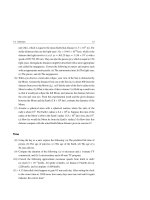
For monochromatic light, Fig. 18.14 shows a sharp intensity distribution for the
maxima and a broad distribution in the dark areas.
I
1
2
1
2
λ /d
2 λ /d
0
m
sin θ
2 λ /d
λ /d
0
Fig. 18.14 A sketch of the intensity versus sin θ for a diffraction grating. The zeroth-, first-, and secondorder maxima are shown. The sharpness of the maxima and the broadness of the minima are shown
We can use this technique to distinguish and identify light of several unknown
wavelengths. We cannot do that with the double-slit arrangement of Sect. 18.2, even
though the same equation and wavelength dependencies apply there. In a double-slit
interference, the bright fringes due to different wavelengths overlap too much to be
distinguished.
Resolving Power of the Diffraction Gratings
Diffraction gratings are useful tools for accurately measuring wavelengths. To resolve
two similar light sources with nearly equal wavelengths λ1 and λ2 (near a wavelength
λ), the diffraction grating should have a high resolving power R, defined in terms
of the average wavelength λav and the wavelength difference
R=
λav
λ
λav =
λ1 + λ2
2
λ,
λ as:
λ = λ2 − λ 1
(18.30)
If N is the number of illuminated slits in the grating, then it can be shown that the
resolving power in the mth-order diffraction is:
R=N m
(18.31)
Thus, R increases as N and m increase. When m = 0, we know that all the wavelengths
are indistinguishable and hence R = 0 as expected.
18.5 Diffraction Gratings
623
Example 18.9
A diffraction grating has 7,000 lines per centimeter. When the grating is illuminated normally with a monochromatic light, the second order spectral line is
found at 62◦ .
(a) What is wavelength of the light? (b) Where can we observe the third order
maximum?
Solution: (a) First, we must find the slit separation d as follows:
d=
1 cm
= 1.429 × 10⁻⁴ cm = 1,429 nm
7,000
Then, we use d sin θm = m λ with m = 2 to find the wavelength:
λ=
(1,429 nm) sin 62◦
d sin θ2
=
= 631 nm
2
2
(b) For m = 3, we calculate sin θ3 as follows:
sin θ3 =
3λ
3 × 631 nm
=
= 1.33
d
1,429 nm
Since sin θ3 cannot exceed unity, then this order cannot be observed.
Example 18.10
A diffraction grating 1 cm wide has N = 1,000 equally spaced slits across its
width. The diffraction grating is illuminated at normal incidence by a sodiumvapor yellow lamp. The yellow light (known as the sodium doublet) contains
two colors, one with wavelengths λ1 = 589.0 nm and the other with wavelength
λ2 = 589.6 nm. (a) What is the separation between the slits of the grating? (b)
How many bright fringes are seen for both colors? (c) What must the resolving
power of the grating be if the two colors are to be resolved (distinguished)? (d)
How many slits of this grating must be illuminated in order to resolve these two
colors in the fourth-order?
Solution: (a) The ruling separation distance d is:
d=
1 cm
= 10−3 cm = 104 nm
1,000
(b) Maxima occur at sin θm = m λ/d (m = 0, 1, 2, . . .). This condition is accepted only if m λ/d < 1, or m < d/λ. We select the larger wavelength λ2 = 589.6 nm
to find the possible values of m as follows:
624
18 Interference, Diffraction and Polarization of Light
m<
d
104 nm
= 16.96
=
λ2 589.6 nm
Thus, the orders m = 0, 1, 2, . . . , 16 are seen in the diffraction pattern.
(c) With λav = (λ1 + λ2 )/2 = 589.3 nm and
calculate the resolving power as follows:
R=
λ = 0.6 nm, we use Eq. 18.30 to
λav
589.3 nm
=
= 982
λ
0.6 nm
(d) Using Eq. 18.31 and R = 982, we find that:
N =
982
R
=
= 246
m
4
Thus, in order to resolve the yellow sodium doublet up to a 4th -order maximum,
we must illuminate at least N = 246 slits.
18.6
Polarization of Light Waves
Light propagates in vacuum with a speed c = 2.9979 × 10⁸ m/s, see Chap. 27.
As shown in Fig. 18.15a, light waves have the properties of transverse electromag→
→
netic waves, with an electric field vector E and a magnetic field vector B vibrating in
→
→
two planes perpendicular to each other. In addition, E and B propagate with velocity →
c in the direction of the light wave, which is perpendicular to both.
→
The direction of vibration of E for an individual wave is defined as the direction of
polarization of the wave. However, an ordinary beam of light contains a large number
of electromagnetic waves emitted by atoms having random vibrational orientations,
→
and hence the direction of the electric field vector E in the beam is random. In this
case the beam of light is unpolarized.
→
An electromagnetic wave is said to be polarized if the electric field vector E at a
given position vibrates in the same direction at all times. The plane of polarization
→
is defined as the plane containing E and the direction of propagation →
c. Fig. 18.15a
displays a schematic diagram for a light wave polarized along the y axis. Fig. 18.15b
represents an unpolarized light beam and Fig. 18.15c represents a polarized beam,
both viewed along the direction of propagation.
A bean of unpolarized light can be polarized by reflection, refraction, scattering,
or absorption.
18.6 Polarization of Light Waves
625
Representation of
unpolarized light
y
E
Representation of
polarized light
E
E
B
x c
z
c ⊥ to the page
c ⊥ to the page
(b)
(c)
(a)
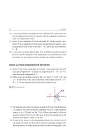
Fig. 18.15 (a) An electromagnetic wave propagating in the x direction with velocity →
c , where →
c is
→
→
perpendicular to both E and B . (b) A sketch representing an unpolarized light beam. (c) A sketch
representing a polarized light beam
In 1938, E. H. Land invented a polarizing sheet called Polaroid. This sheet trans→
mits waves whose electric fields E vibrate in a certain direction (called the transmission axis) and absorbs waves whose electric fields vibrate in a perpendicular
direction.
Figure 18.16 represents an unpolarized light beam incident first on a polarizing
sheet, called the polarizer. Because the transmission axis is vertical in the figure, the
light transmitted through this sheet is polarized vertically with an electric field vector
→
denoted by E ◦ . A second polarizing sheet, called the analyzer, with transmission axis
making an angle θ with the polarizer, intercepts the beam. The only component that
→
is allowed through by the analyzer is E cos θ, while other components are absorbed.
Polarizer
E
°
Analyzer
θ
Unpolarized light
Transmission axis
E cos θ
°
Polarized light
Fig. 18.16 Two polarizing sheets whose transmission axes make an angle θ with each other. Only a
fraction of the polarized light incident on the analyzer is transmitted through it
Since the intensity of the transmitted beam varies as the square of the electric
field, then the intensity of the polarized beam transmitted through the analyzer varies
with θ, and is given by Malus’s law as:
626
18 Interference, Diffraction and Polarization of Light
I = I◦ cos2 θ
(18.32)
where I◦ is the intensity of the polarized beam incident on the analyzer. This expression applies to any two polarizing materials where their transmission axes are placed
at an angle θ to each other.
Example 18.11
→
A plane-polarized light wave E◦ sin ωt of intensity I◦ makes an angle θ with
the transmission axis of a Polaroid sheet. What fraction of the original light is
transmitted through the Polaroid?
Solution: The incident polarized wave is equivalent to two mutually perpendicular
→
→
components. One component is parallel to the transmission axis E = (E◦ cos θ )
→
→
→
sin ω t and the other is perpendicular to it E⊥ = (E◦ sin θ ) sin ωt. Since E is the
only transmitted component through the Polaroid with an intensity I proportional
to the square of its amplitude, see Fig. 18.17, then:
→
→
I
(E ◦ cos θ ) • (E◦ cos θ )
=
= cos2 θ
→ →
I◦
E◦ • E◦
Or:
I = I◦ cos2 θ
Which is Malus’s law.
Fig. 18.17
E°
Polaroid
I°
θ
E° cos θ
I
Transmission axis
Example 18.12
Unpolarized light of intensity I◦ is incident on a Polaroid sheet with a vertical
transmission axis, see Fig. 18.18. What is the intensity I of the transmitted beam?
Solution: We recall that the incident wave consists of a multitude of randomly
oriented electric fields. Then, Eq. 18.32 applies to each electric field, but with
18.6 Polarization of Light Waves
627
angle θ ranging from 0◦ to 360◦ . Because the orientation is random, all values of
θ will occur equally. As a result, Eq. 18.32 will give us the transmitted intensity
if we use the average value of cos2 θ.
Thus, I = I◦ cos2 θ , where cos2 θ = 21 .
Then: I = 21 I◦ (as indicated in Fig. 18.18)
Fig. 18.18
Unpolarized light
I°
Polarized light
I = 12 I°
Transmission axis
18.7
Exercises
Sections 18.1 and 18.2 Interference of Light Waves and Young’s
Double-Slit Experiment
(1) Two identical narrow slits are separated by a distance d = 0.3 mm. The slits
are illuminated by a monochromatic red light of wavelength λ = 630 nm. An
interference pattern is observed on a screen at a distance D = 1.2 m from the
plane of the slits. Find the separation between adjacent bright fringes.
(2) Two narrow slits are separated by a distance d = 0.05 mm and are 2 m away
from a screen. When the slits are illuminated by a monochromatic light of
unknown wavelength λ, we obtain a second-order bright fringe 4 cm from the
central line. Find the wave length of the light.
(3) When white light is used instead of the monochromatic light in Exercise 2, the
first-order fringe of the observed interference pattern resembles a rainbow of
violet and red light at the fringe border. The approximate locations of the violet
and red light on the screen are y1V = 16 mm and y1R = 28 mm from the central
line. Estimate the wavelengths of the violet and red light.
(4) In a Young’s double-slit experiment, monochromatic light is diffracted from
two narrow slits 0.4 mm apart. Near the central line, successive bright and dark
fringes that are 6 mm apart are both viewed on a screen 4 m away. Find the
wavelength and frequency of the light.
628
18 Interference, Diffraction and Polarization of Light
(5) In a double-slit experiment, the fifth-order bright fringe produced by light of
wavelength 450 nm is observed at an angle of 30◦ from the central line. How
far apart are the two slits?
(6) What are the expected angles of all dark fringes preceding the fifth-order bright
fringe of Exercise 5?
(7) A blue light of wavelength λB = 475 nm and yellow light of wavelength
λY = 570 nm pass through a Young’s double-slit apparatus. Blue and yellow
patterns of fringes are formed on the screen of the experiment. At the central
bright fringe, where mV = mB = 0, both the blue and yellow light mix and form
a green fringe. What is the next order of the blue and yellow fringes that overlap
on the screen to form a green fringe?
(8) Two narrow slits that are 0.015 mm apart in a Young’s double-slit experiment
are illuminated by a green laser beam of wavelength λG = 510 nm. (a) What
will be the total number of bright fringes that will be formed on both sides of
a very large distant screen? (b) What angle does the most distant bright fringe
from the central fringe make with respect to the original direction of the laser
beam?
(9) Two very narrow slits are 1.5 µm apart and are 25 cm away from a screen. Light
of wavelength 450 nm passes through the double slits, forming an interference
pattern that does not satisfy the condition λ d, i.e., tan θ = sin θ. What is the
distance between the first and second dark fringes of the interference pattern
on the screen?
(10) A double-slit experiment is designed for easy viewing in a classroom such that
the distance between the central maximum and the first maximum is 30 cm.
The wavelength of the He-Ne red laser light used in the experiment is 634 nm,
and the viewing screen is 9 m away from the double slits. What slit separation
is required for such an interference pattern?
(11) Light of wavelength 600 nm passes through two slits that are 0.5 mm apart.
What is the phase difference between two parallel diffracted light rays making
an angle 15◦ with the central line?
(12) The peak intensity of a two-slit interference pattern is denoted by I◦ and the
variation of the intensity as a function of the phase difference is given by
Eq. 18.12. Assume a point in the pattern where the phase difference between
waves from the two slits is π/3 rad. (a) What is the intensity of the pattern at
this point? (b) What is the path difference between waves at this point when
light of wavelength λ = 567 nm is used?
18.7 Exercises
629
(13) Two narrow slits 0.15 mm apart are illuminated by 634 nm light and their interference pattern is viewed on a screen 1.2 m meters away from the slits. Find the
intensity (relative to the central maximum) of the interference pattern 3.5 cm
above the central line.
(14) Show that the relation 2d sin θ = (m + 21 )λ, m = 0, 1, 2, . . . gives the angle θ at
which the double-slit intensity is one-half of the peak value, i.e., when I = 21 I◦ .
(15) Using the relation obtained in Exercise 14 for half the intensity at the peak,
show that the angular displacement from the half-intensity position on one side
of the central maximum to the half-intensity position on the other side is given
by the relation θ = λ/2d. (Hint: sin θ θ when θ is small)
Section 18.3 Thin Films—Change of Phase due to Reflection
(16) An oil film has an index of refraction n = 1.5. Monochromatic light of wavelength λ = 600 nm is incident normally on the film. (a) What is the smallest
thickness of the film that will give a maximum interference in the reflected light
view? (b) Would tripling the thickness calculated in part (a) produce maximum
interference in the reflected light view?
(17) A soap bubble has an index of refraction n = 1.32 and is 130 nm thick. White
light is incident normally on the outer surface of the bubble. What is the wavelength of the color that reflected from the bubble’s outer surface?
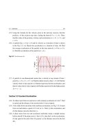
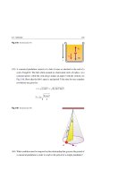
(18) Two glass plates are in contact at one edge and separated by a very fine separator at the other end to form a wedge as shown in Fig. 18.19. The wedge
is illuminated normally from above by light of wavelength λ = 589 nm. When
the wedge is viewed vertically, six dark fringes are observed between the left
edge and the last dark fringe located at the separator, see Fig. 18.19. Find the
height of the separator.
Fig. 18.19 See Exercise(18)
λ
Almost normal
Air film
(Exaggerated)
Dark fringes
d
D
D
D
D
D
D
Separator
630
18 Interference, Diffraction and Polarization of Light
(19) Assume that the separator in Fig. 18.19 has a height d = 6,000 nm. (a) How
many dark and bright bands will be seen in the wedge area? (b) Assume that
the glass plates are 20.5 cm long and the dark and bright bands are equal in
thickness. How far apart are the bright bands?
(20) A soap film has an index of refraction n = 1.32. The film is illuminated normally
by light of wavelength λ = 445 nm. (a) What is the smallest thickness of the
film that it will appear black? (b) Why would the film also appear black if the
film thickness is much less than the wavelength?
(21) A lens of index of refraction nL = 1.52 appears green (λ = 510 nm, i.e., reflects
most of the green) when white light is shined on its surface. One solution to
avoid this effect is to coat the surface of the lens with a film of material that has
an index of refraction nC = 1.25. What is the minimum thickness of coating
required such that the coating interferes constructively with the green light?
(22) Figure 18.20 shows a very thin film of oil (no = 1.5) with variable thickness.
The oil is floating on water (nw = 1.33). The film is illuminated from above by
white light, which causes a sequence of highly distinguished colors to appear as
shown in the figure. Take blue to have λ = 445 nm, yellow to have λ = 570 nm,
and red to have λ = 650 nm. (a) Find the minimum and maximum thickness
of the variable thickness of the oil film. (b) Explain the existence of the dark
Oil
Water
Red
Yellow
Blue
Red
Yellow
Blue
Dark
Blue
Yellow
Red
region in the oil film.
Air
no = 1.5
nw = 1.33
Fig. 18.20 See Exercise (22)
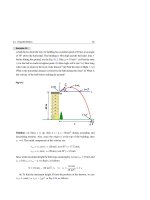
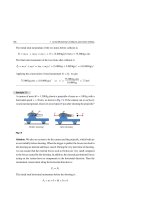
(23) The radius of curvature of the convex surface of a plano-convex thin lens
is R = 5 m. The convex surface is placed down on a plane glass plate and
illuminated from above by light of wavelength λ = 450 nm, see Fig. 18.21. (a)
What is the change in thickness of the air film between the third d3 and the
sixth d6 bright fringes in the reflected light view? (b) What is the radius r4 of
the fourth bright fringe?
18.7 Exercises
R
r
631
1 2
R
r
r
λ
r4
1
2 3 4 56
Air film
(Exaggerated)
d
P
Almost normal
O
Fig. 18.21 See Exercise(23)
(24) When viewing the Newton’s rings from above, use the geometry of Fig. 18.21
to show that the radius rm of the mth dark ring when rm R is given by
√
rm = mλR/nfilm , where nfilm is refractive index of the film. [Hint: Use the
binomial expansion (1 − x)n 1 − nx, when x 1.]
(25) Use the result of Exercise 24 to show that the distance r between adjacent
√
dark Newton’s rings of order m and m + 1 is given by r = λR/4mnfilm ,
when m
1.
(26) The maximum ring radius in Fig. 18.21 is r = 1.5 cm and corresponds to the
32th dark ring. (a) What is the radius of curvature of the plano-convex lens if
light of wavelength λ = 570 nm is used? (b) What is the focal length of the lens
if its refractive index is n = 1.52?
Sections 18.4 and 18.5 Diffraction of Light Waves and
Diffraction Gratings
(27) A beam of red light from a helium-neon laser is diffracted by a slit of
width a = 0.5 mm. A diffraction pattern is formed on a screen at a distance
D = 1.9 m from the slit. The distance between the zero intensities on either
side of the central peak is 4.81 mm. (a) Find the wavelength of the laser light.
(b) Calculate the ratio of the intensities of the third maximum to the central
maximum.
(28) Monochromatic light of wavelength λ = 480 nm is diffracted by a single slit
of width a = 4.5 × 10⁻³ mm. A diffraction pattern is formed on a screen at
632
18 Interference, Diffraction and Polarization of Light
a distance D = 7 m away from the slit. Assuming that the angle of the first
maximum is equal to the average of the angles of the first and second minima,
estimate how far the first maximum is from the central maximum.
(29) A single slit diffracts light of wavelength λ = 650 nm. When the screen is at a
distance D = 4 m away from the slit, the central maximum is 2 cm wide. What
is the width of the slit?
(30) (a) What will be the minimum value of a single slit of width a that will not
produce diffraction minima for a given wavelength λ? (b) What will be the
minimum value of the width a that will not produce diffraction minima for
the whole range of visible light (with the approximate range from 400 nm to
700 nm)?
(31) A single slit 1.5 µm wide is illuminated by 634 nm light and its diffraction
pattern is viewed on a screen 53.6 cm away from the slit. (a) What is the height
of the first minimum above the central maximum? (b) As a fraction of the
central maximum’s intensity I◦ , determine the light intensity 10 cm above the
central maximum.
(32) The secondary maxima in Eq. 18.26 do not occur precisely at the maximum
of the sine function. This is because the denominator of the intensity function
causes the intensity to decrease more rapidly than the sine function causes it
to increase. Consequently, the intensity reaches a maximum slightly before the
sine function reaches its maximum. By differentiating Eq. 18.26 with respect
to δ/2, show that the secondary maxima occur when δ/2 satisfies the condition
tan δ/2 = δ/2.
(33) A diffraction grating has 8,000 grooves per centimeter. The first order of the
spectral line is observed to be diffracted at an angle of 30◦ . What is the wavelength of the light used?
(34) A diffraction grating has 5,000 lines per centimeter. The grating is illuminated
normally with the green light of mercury, which has a wavelength λ = 546.1 nm.
What is the angular separation between the first and second-order green lines?
(35) A diffraction grating has N = 4,000 equally spaced slits per centimeter. The
diffraction grating is illuminated at normal incidence by the doublet colors
of wavelengths λ1 = 732 nm and λ2 = 733 nm, emitted by a singly-ionized
Oxygen atom. (a) What is the separation between the slits of the grating?
(b) How many bright fringes are seen for both colors? (c) What should the
18.7 Exercises
633
resolving power of the grating be if these two colors are to be distinguished?
(d) How many slits of this grating must be illuminated in order to resolve these
two colors in the second-order?
(36) A diffraction grating has 4,500 lines per centimeter. The grating is illuminated
normally by white light (wavelengths ranging from 400 nm to 700 nm). How
many spectral orders can be observed?
(37) Use the data of Exercise 36 to find the width of the first-order spectrum on a
screen 0.5 m away from the grating.
(38) Find the range of wavelengths of the second-order spectra of a diffraction
grating of white light that overlap with the range of wavelengths of the thirdorder spectra.
(39) A diffraction grating has 6,200 lines per centimeter and is illuminated by light
with λ = 525 nm. The light falls normally on its surface. (a) What is the maximum possible order for this grating? (b) What order gives the best resolution?
(c) How close can two wavelengths be if they are to be resolved in the maximum
order?
Section 18.6 Polarization of Light Waves
(40) A beam of polarized light has one-fifth of its initial intensity after passing
through an analyzer. What is the angle between the axis of the analyzer and the
initial polarization direction of the beam?
(41) The transmission axes of two polarizers are oriented at 60◦ to one another.
Unpolarized light of intensity I◦ falls on them. What fraction of light is transmitted through them?
(42) If the light in Exercise 41 was polarized and the transmitted intensity from
the two polarizers is 0.125 I◦ , what is the angle between the axis of the first
polarizer and the initial polarization direction of the beam?
(43) Two polarizers are oriented 60◦ to one another. Light of intensity I◦ gets polarized as it passes through these polarizers at half the orientation angle between
them. What fraction of light intensity is transmitted through both of them?
(44) Determine the angle in Exercise 43 that will make the two polarizers transmit
only half of the incident light intensity.
(45) An ordinary light of intensity I◦ is incident on one Polaroid sheet and then falls
on a second Polaroid sheet whose transmission axis makes an angle θ = 30◦
634
18 Interference, Diffraction and Polarization of Light
with the first, see Fig. 18.22. (a) Find the intensity fractions I1 /I◦ , I2 /I1 , and
I2 /I◦ . (b) If the second Polaroid is rotated until the transmitted intensity is 10%
of the incident intensity I◦ , what is the new angle?
Unpolarized light
Polaroid 1
θ
I
°
Transmission axis
Fig. 18.22 See Exercise(45)
I1
I2
Polaroid 2
Part V
Electricity
Electric Force
19
In this chapter, we study one of the fundamental forces of nature, the electric force.
Electrical forces play an important role in the structure of atoms, molecules, and
nuclei. We will discuss the following:
(1) The existence of electric charges and electric forces.
(2) The basic properties of electrostatic forces.
(3) Coulomb’s law, which is the fundamental law governing electric forces between
charged particles.
(4) The application of Coulomb’s law to simple charge distributions.
19.1
Electric Charge
Many simple experiments indicate the existence of electric forces and charges. It is
possible to impart an electric charge to any solid material by rubbing it with another
material. The rubbed solid material is said to be electrified, or electrically charged.
For example, a comb becomes electrified when it is used to brush dry hair. This is
justified by observing that the comb will attract bits of paper.
Many experiments conducted by Benjamin Franklin reveal that there are two
types of electric charges: positive and negative. A glass rod that has been rubbed
with silk is commonly used as an example for identifying positive and negative
charges. Another common example is a hard rubber rod that has been rubbed with
fur. Using Franklin’s convention, positive charges are formed on a glass rod that has
been rubbed with silk, and negative charges are formed on a rubber rod that has been
rubbed with fur.
H. A. Radi and J. O. Rasmussen, Principles of Physics,
Undergraduate Lecture Notes in Physics, DOI: 10.1007/978-3-642-23026-4_19,
© Springer-Verlag Berlin Heidelberg 2013
637
638
19 Electric Force
When a positively charged glass rod is brought close to a suspended negatively
charged rubber rod, the two rods attract each other, see Fig. 19.1a. Conversely, if two
positively charged glass rods (or two negatively charged rubber rods) are brought
close to each other, the two rods repel each other, see Fig. 19.1b.
F
Rubber
Glass
F
F
Glass
(a)
F
Glass
(b)
Fig. 19.1 (a) A negatively charged rubber rod attracting a positively charged glass rod. (b) A positively
charged glass rod repelling another positively charged glass rod
Based on these observations, we conclude that there are two kinds of charges
in nature; one is positive and the other is negative, and they obey the following
properties:
Spotlight
Like charges repel each other and unlike charges attract each other.
Additionally, it was found that when one object is rubbed with another, charge is
transferred between them, i.e. charge is not created in the rubbing process. That is:
Spotlight
The total charge in any isolated system is conserved.
In 1909, Robert Millikan discovered that an electric charge always occurs in
integral multiples of a fundamental charge e. In a modern view, the electric charge q is
said to be quantized and we can write q = ne, where n is an integer (n = ±1, ±2, . . .).
That is:
19.1 Electric Charge
639
Spotlight
Charge is quantized.
In today’s modern scientific views, an electric charge is considered to be a basic
property of atoms. As we all know, an atom is the fundamental entity of which
all matter is formed. Atoms themselves are composed of three types of particles—
protons, electrons, and neutrons. A proton carries one unit of positive charge +e, an
electron carries one unit of negative charge −e, and a neutron carries no charge; it is
electrically neutral.
Based on the charge conservation and the atomic structure, we find that when
a glass rod is rubbed with silk, electrons are transferred from the glass to the silk
giving the silk a net negative charge and consequently leaving a net positive charge
of the same magnitude on the glass, see Fig. 19.2. Similarly, when a rubber rod is
rubbed with fur, electrons are transferred from the fur to the rod, giving the rod a net
negative charge, leaving the fur with a net positive charge.
Fig. 19.2 When a neutral
Neutral Glass
Glass
glass rod is rubbed with a
neutral silk cloth, electrons are
transferred from the glass to
Silk
Neutral Silk
the silk, leaving the glass
positively charged
Before rubbing
19.2
After rubbing
Charging Conductors and Insulators
Materials can be classified according to their ability to conduct electrical charge. In
some materials, such as metals (copper, aluminum, etc), tap water, and the human
body, some of the negative charges (electrons) can move rather freely. We call such
materials conductors.
Spotlight
Conductors are materials containing some electrons that can move freely.
640
19 Electric Force
In contrast, charges cannot move freely in some other materials such as glass,
rubber, and plastic. We call such materials nonconductors or insulators.
Spotlight
Insulators are materials that contain electrons that are bound to their atoms and
cannot move freely through the material.
Semiconductors are materials that lie somewhere between conductors and insulators, such as silicon and germanium. The electrical properties of semiconductors
can be changed drastically by adding specific amounts of certain atoms (impurities).
Generally, the conductivity of semiconductors increases with increasing temperature,
in contrast to metallic conductors. The microelectronic revolution that has changed
our lives is due to devices constructed of semiconductors.
Spotlight
Semiconductors are materials that have electrical properties that lie somewhere
between conductors and insulators, such as silicon and germanium.
Charging a Conductor by Rubbing
When a person rubs a copper rod with wool while holding it in his hand, he will not
be able to charge the rod. The reason is that both the rod and his body are conductors.
The rubbing will cause a charge imbalance on the rod, but the excess charge will
immediately flow from the rod through his body to the Earth, and the rod will be
neutralized immediately. Conversely, if the experiment is repeated while the rod is
held by an insulating handle, we would eliminate the conducting path to Earth, and
the rod can then be charged.
Charging a Conductor by Induction
Another way of charging a conductor is shown in Fig. 19.3. Figure 19.3a shows a
negatively charged plastic rod and an isolated neutral copper rod that is suspended
by an insulated twistable wire. When the plastic rod is brought into the vicinity of
the copper rod, many of the conduction electrons in the closer end of the copper rod
19.2 Charging Conductors and Insulators
641
are repelled by the negative charge on the plastic rod. They move to the far end of
the copper rod, leaving the near end depleted in electrons. Such repulsion of negative
charges from the near end leaves that end positively charged. This positive charge is
attracted to the negative charge in the plastic rod as shown in Fig. 19.3b. Although as a
whole, the copper rod is still neutral, it is said to have an induced charge. At this state,
if we ground the copper rod, as shown in Fig. 19.3c, some of the negative charges
move out of the rod through the wire into the Earth. Earth can accept or provide
electrons freely with negligible effect on its electrical characteristics. When the wire
to the ground is removed, the conducting copper rod remains in an induced positive
charge state, see Fig. 19.3d. When the plastic rod is removed from the vicinity of the
copper rod, this induced positive charge remains and is distributed on the rod, see
Fig. 19.3e.
This process can be repeated with a positively charged glass rod to obtain a
negatively charged copper rod.
Induced
charge
Neutral
copper
F
F
F
F
F
F
Charged copper
Charged
plastic
(a)
(b)
(c)
(d)
(e)
Fig. 19.3 (a) A negatively charged plastic rod is kept far away from a neutral copper rod. (b) The electrons
on the copper rod are redistributed when the charged plastic rod is brought into the vicinity of the copper
rod. (c) When the copper rod is grounded, some of the electrons move into the Earth. (d) Removing the
ground connection. (e) Removing the plastic rod to obtain a positively charged conductor
Charging an Insulator by Induction
In most of the neutral molecules of insulators, the center of positive charge coincides
with the center of negative charge. In the presence of a charged object, the charged
centers of each molecule in the insulator may shift slightly. The molecule is then said
to be electrically polarized. This produces a layer of induced charge on the insulator
surface as shown in Fig. 19.4a. Consequently, the charged object and the insulator
will attract each other, see Fig. 19.4b.
642
19 Electric Force
Polarized
molecule
Induced charge
Charged
comb
Charged
object
Neutral
insulator
Neutral bits
of paper
(a)
(b)
Fig. 19.4 (a) A negatively charged object produces an induced charge on the surface of an insulator
because charges in the molecules of the insulator are electrically polarized. (b) A charged comb attracts
small bits of dry paper due to the effect of molecular polarization
19.3
Coulomb’s Law
In an experiment to measure the magnitude of the electrical force F between two
charged particles separated by a distance r and having charges q1 and q2 , Charles
Coulomb was able to find that:
F=k
|q1 | |q2 |
r2
(Coulomb’s law)
(19.1)
This formula is known as Coulomb’s Law, and k is a constant called the Coulomb
constant. Coulomb found that each charged particle (also called a point charge)
exerts a force of this magnitude on the other particle, and the two forces form an
action–reaction pair. It was found that charges of the same sign repel each other,
while charges of opposite signs attract each other, see Fig. 19.5. The SI unit of a
charge is the coulomb (abbreviated by C) and is derived from the SI unit of electric
current, the ampere (abbreviated by A) which will be defined in Chap. 24.
The form given by Eq. 19.1 resembles Newton’s force law that describes the
universal gravitation between two objects of masses m1 and m2 that are separated by
a distance r, see Fig. 19.6. That is:
F =G
m1 m2
r2
(Newton’s gravitational law)
where G = 6.67 × 10⁻¹¹ N.m2 /kg2 is the gravitational constant.
(19.2)