Hafez a radi, john o rasmussen auth principles of physics for scientists and engineers 2 35
Bạn đang xem bản rút gọn của tài liệu. Xem và tải ngay bản đầy đủ của tài liệu tại đây (666.84 KB, 20 trang )
24.7 The RC Circuit
843
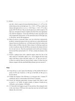
Fig. 24.24
S
R
+Q
C
-Q
t<0
Solution: (a) The time constant of the circuit is:
τ = R C = (2 × 10³ )(5 × 10⁻⁶ F) = 10−2 s = 10 ms
After closing the switch at t = 0, the charge on the capacitor is given by Eq. 24.49,
q = Qe−t/τ . To find the time interval during which q drops to one-half its initial
value, we substitute q = Q/2 into this equation and solve for the time t as follows:
Q
= Qe−t/τ
2
⇒
1
= e−t/τ
2
Taking the logarithm of both sides, we find:
− ln 2 = −
t
τ
⇒
t = (ln 2)τ = 0.69τ = 0.69 × (10 ms) = 6.9 ms
(b) From Eq. 23.24, the initial stored energy in the capacitor is U◦ = Q2 /2C.
Using Eq. 24.49, the energy stored at time t is:
U=
q2
Q2 −2t/τ
=
e
= U◦ e−2t/τ
2C
2C
As in part (a), we set U = U◦ /2 and solve for t as follows:
U◦
= U◦ e−2t/τ
2
⇒
1
= e−2t/τ
2
Again, taking the logarithm of both sides and solving for t, we find:
− ln 2 = −2t/τ
⇒
t = 21 (ln 2)τ =
1
2
× 0.69τ =
1
2
× 0.69 × (10 ms) = 3.45 ms
Note that the results of both parts are independent on the value of Q.
844
24.8
24 Electric Circuits
Exercises
Section 24.1 Electric Current and Electric Current Density
(1) How many electrons per second would pass through a given cross section of a
conductor carrying a current I = 1.6 A?
(2) A current of 10 A is maintained in a wire for 1 min. (a) How much charge flows
through the wire in this period? (b) How many electrons flow through the wire
in this period?
(3) A 0.1 mol of electrons flows through a wire in 30 min. (a) What is the total
charge that passes through the wire? (b) What is the value of the current in the
wire?
(4) A copper wire contains 2 × 10²¹ free electrons in 1 cm of its length. The electrons move with a drift speed of 2.5 × 10⁻³ cm/s. (a) How many electrons pass
through a given cross section of the wire each second? (b) How large is the
current in the wire?
(5) The current through a cross-sectional area of a wire is given by the relation
I = 2 + 3t 3 ; where I is in amperes and t is in seconds. (a) Find the total charge
that passes through this area between t = 2 s and t = 8 s. (b) Find the average
current needed to pass the same quantity of charge calculated in part (a) during
the same time interval.
(6) The charge that passes a cross-sectional area A = 10−4 m2 varies with time
according to the relation Q = 4 + 2t + t 2 , where Q is in coulombs and t is in
seconds. (a) Find the relation that gives the instantaneous current at any time,
and evaluate this current at time t = 2 s. (b) Find the relation that gives the
current density at any time, and evaluate this current density at time t = 2 s.
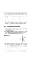
(7) A wire carrying a current of 3 A has a circular cross section everywhere with a
non-uniform radius, see Fig. 24.25. The radius of the cross section A1 is 2 cm.
(a) Find the current density across A1 . (b) Find the current density across A2 if
its radius is two times the radius at A1 .
(8) A copper wire with a 0.2 mm diameter and an iron wire with a 5 mm diameter
are soldered together to form one wire in a circuit. A current of 8 A is found
to pass through the copper wire. (a) What is the current and current density
through the iron wire? (b) What is the current density through the copper
wire?
24.8 Exercises
845
Fig. 24.25 See Exercise (7)
A2
I
A1
I
I
(9) Given that the density of aluminum is 2.7 × 10³ kg/m3 , find the drift speed of
the conduction electrons in an aluminum wire that has a cross-sectional area
of 10−6 m2 and carries a current of 10 A. Assume that each aluminum atom
contributes one free conduction electron to the current.
Section 24.2 Ohm’s Law and Electric Resistance
(10) Use Table 24.1 to calculate the electric field that exists in a gold wire when the
current density in the wire is 3 × 10⁷ A/m2 .
(11) A metallic rod has a length L = 1.5 m and a diameter D = 0.2 cm. The rod
carries a current of 5 A when a potential difference of 75 V is applied between
its ends. (a) Find the current density in the rod. (b) Calculate the magnitude of
the electric field applied to the rod. (c) Calculate the resistivity and conductivity
of the material of the rod.
(12) Use Table 24.1 to calculate the resistance of a silver wire that has a length of
100 m and a cross section of 0.4 mm2 .
(13) At 20 ◦ C, a silver wire has a diameter of 2 mm, a length of 0.5 m, a resistivity
of 1.6 × 10⁻⁸ .m, a temperature coefficient of resistivity of 4 × 10⁻³ (C◦ )−1 ,
and carries a current of 5 A. (a) What is the current density in the wire? (b)
Find the magnitude of the electric field applied to the wire. (c) What is the
potential difference between the ends of the wire? (d) What is the resistance of
the wire? (e) Find the temperature of the wire when its resistance increases to
6.5 × 10⁻⁴ .
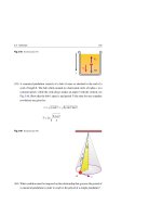
(14) A cylindrical shell of length L = 10 cm is made of copper and has an inner
radius a = 2 mm and an outer radius b = 8 mm, see Fig. 24.26. Assume that the
shell has a uniform current density J = 105 A/m2 directed upward as shown in
the figure. (a) What is the current through the shell? (b) What are the values of
the resistance of the shell and the potential difference
V?
846
24 Electric Circuits
Fig. 24.26 See Exercise (14)
Uniform Current density
J
a
b
J
I
V
L
S
I
(15) A cube of copper has a mass m = 50 g, see Fig. 24.27. The copper has a density of 8.92 × 10³ kg/m3 , a molar mass of 63.546 kg/kmol, a resistivity of
1.7 × 10⁻⁸ .m, and contributes one conduction electron per atom. (a) What
is the distance between opposite faces of the cube? (b) What is the resistance
between opposite faces of the cube? (c) What is the current and the average drift
speed of the conduction electrons when a potential difference V of 10−4 V is
applied between two opposite faces of the cube?
Fig. 24.27 See Exercise (15)
I
A
V
L
I
(16) The temperature coefficient of resistivity of copper at 20 ◦ C is 3.9 × 10⁻³ (C◦ )−1 .
Calculate the percentage increase in its resistivity when its temperature increases
to 220 ◦ C.
(17) At a temperature of 1,800 ◦ C the tungsten filament of a light bulb has a resistance of 250 . With the aid of Table 24.1, find its resistance at room temperature (assume it to be 20 ◦ C).
(18) At 20 ◦ C a copper wire has a resistance of 4 × 10⁻³
and a temperature coef-
3.9 × 10⁻³ (C◦ )−1 .
ficient of resistivity of
What is its resistance at 100 ◦ C?
(19) At 70 ◦ C, an electric field E = 0.2 V/m is applied along a silver rod of length
L = 0.5 m and radius r = 0.05 mm. Silver has a density of 10.5 × 10³ kg/m3 ,
24.8 Exercises
847
a molar mass of 107.868 kg/kmol, a coefficient α at 20 ◦ C of 3.8 × 10⁻³ (C◦ )−1 ,
and a resistivity of 1.59 × 10⁻⁸ .m at 20 ◦ C. Assuming 1 free electron per
atom, find: (a) the resistivity of the silver wire (b) the current density in the
silver wire. (c) the current in the silver wire. (d) the resistance of the silver
wire. (e) the drift speed of the conduction electrons. (f) the potential difference
between the ends of the silver wire.
(20) At 20 ◦ C, a nichrome wire of resistance R◦n and a carbon wire of resistance R◦c are attached end-to-end to form one wire of resistance R◦ , where
R◦ = R◦n + R◦c = 9 . What values of R◦n and R◦c would give a combined
resistance of R equal to R◦ regardless of the temperature T? [Hint: use
Table 24.1.]
Section 25.3 Electric Power
(21) A light bulb rated 60 W at 240 V is operated from a 240 V source. (a) Find the
current flowing through the bulb. (b) Find the resistance of the bulb. (c) Repeat
(a) and (b) when the bulb is rated 100 W at 240 V.
(22) A 550 W electric heater is designed to operate from a 220 V source. (a) What
is the resistance of the heater? (b) What current does the heater draw from the
source? (c) If the source voltage drops to 120 V, what power does the heater
consume from the source?
(23) A heating coil is made from a nichrome wire of radius 0.45 mm. The coil is
designed to produce 240 W of thermal power when connected to a source that
has a potential difference of 24 V. (a) What is the resistance of the coil? (b) What
current does the heating coil draw from the source? (c) What is the length of
the coil?
(24) A 1 k carbon resistor used in an electric circuit is rated 0.4 W. (a) Find the
maximum allowable current that can pass through the resistor. (b) Find the
maximum allowable potential difference that can be applied across the resistor.
(25) Batteries are rated in terms of the quantity I t, i.e. rated in ampere-hours (A.h).
For instance, a battery that can produce a current of 4 A for 5 h is rated as a
20 A.h battery. (a) Find the total energy stored in a 12 V battery rated at 75 A.h.
(Express your answer in kW.h, where 1 kW.h = 3.6 × 10³ J). (b) At a price of
35 piaster per kilowatt-hour of electricity, what is the total cost of the electricity
produced by this battery?
848
24 Electric Circuits
(26) A beam of electrons in a TV set has a radius of 0.1 cm. The electrons move
from the cathode to the screen with an electron current of 0.1 mA and a kinetic
energy of 5 ke V. (a) What is the current density in the beam? (b) How many
electrons per second hit the screen? (c) How much power is dissipated at the
screen? (d) What is the speed of each electron in the beam? (e) Find the number
of electrons per unit volume in the beam.
(27) A heating coil operating from a 220 V source increases the temperature of 2 kg
of water from 20 ◦ C to 50 ◦ C in 20 min. Find the coil’s resistance if water’s
specific heat is 4,186 J/kg.C◦ .
Section 24.4 Electromotive Force
(28) In Fig. 24.28 the circuit contains a battery that has an emf E = 11 V and internal
resistance r = 0.5 . The load in the circuit has a resistance R = 5 . (a) Find
the current in the circuit. (b) Find the potential difference between a and b.
Fig. 24.28 See Exercise (28)
r
a
S
b
I
R
(29) Assume a circuit similar to the one in Exercise 28 has an unknown emf E
and internal resistance r. It is found that when the current is 0.5 A, the load
resistance is 16 . Similarly, it is found that when the current is 1.5 A, the load
resistance is 5 . (a) Find the internal resistance of the battery. (b) Find the emf
of the battery.
(30) Two batteries, one old and the other new, each have an emf of 1.5 V. When
each battery is short-circuited with a conducting wire of zero resistance, it is
found that the new one establishes a 30 A current in the wire while the old one
establishes a 10 A current. Find the internal resistance of the two batteries.
(31) A battery has an emf E 1 = 9 V and an internal resistance r 1 = 0.4 . This
battery is connected to a second battery of E 2 = 12 V and r 2 = 0.6 , and a
light bulb of resistance R. If the batteries are connected with their positive
24.8 Exercises
849
terminals in the same direction as shown in Fig. 24.29, a current of 0.7 A is
established in the circuit. (a) Find the resistance of the light bulb. (b) What
fraction of the transferred chemical energy is dissipated in the two batteries?
(c) If we reverse the polarity of the E 1 = 9 V battery in the circuit, what is the
value of the current in the circuit? Would the answer to part (b) change in this
case?
Fig. 24.29 See Exercise (31)
1
2
r1
r2
S
I
R
Section 24.5 Resistors in Series and Parallel
(32) When three resistors of resistances R1 = 2 , R2 = 1 , and R3 = 4 are connected to a source of potential difference V as shown in Fig. 24.30, the current
in the circuit is found to be 5 A. (a) Find the equivalent resistance of the combination. (b) Determine the value of V .
Fig. 24.30 See Exercise (32)
S
R2
R3
V
R1
(33) For the circuit shown in Fig. 24.31, take R1 = 3 , R2 = 6 , R3 = 12 ,
R4 = 6 , and V = 12 V. (a) Find the equivalent resistance of the combination. (b) Find the current in the branch containing R1 and R2 . (c) Repeat (b)
for the branch containing R3 and R4 . (d) Find the potential difference across
each resistor.
850
24 Electric Circuits
Fig. 24.31 See Exercise (33)
S
R1
R3
R2
R4
V
(34) For each of the combinations shown in Fig. 24.32, find a formula that represents
the equivalent resistance between the terminals A and B.
R
A
R
A
R
R
R
R
R
R
R
R
A
B
R
B
(a)
R
A
(b)
B
(c)
R
R
R
R
R
R
B
(d)
Fig. 24.32 See Exercise (34)
(35) Assume that in exercise 34, R = 2
and VBA = 12 V. For each combination,
find the current in each branch of the circuit. Always start from the branch
closest to A and move toward B.
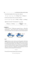
(36) It is recommended that the current through the human body not exceed 150 µA.
Assume a person stands barefoot on the ground, holding a wire connected
through a resistor of high resistance R to a power source of potential difference
V = 220 V as shown in Fig. 24.33. Assume that the circuit’s wire makes a
low-resistance contact with the person’s hand. Also, assume that the resistance
through the person’s body is negligible compared to the resistance R. (a) Find
Rmin , which is the safest resistance value of R. (b) While holding Rmin , the
person decided to wear shoes of resistance RS to reduce the current to 100 µA.
Find RS .
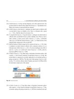
(37) A light bulb is rated 60 W at 240 V. The bulb is connected to a source of
240 V with two equal length wires, each having a resistance R/2 = 120 , see
24.8 Exercises
851
Fig. 24.34. (a) What is the resistance Rb of the light bulb? (b) What is the value
of the current I in the circuit? (c) What is the potential difference between the
sockets of the light bulb? (d) What is the actual power delivered to the bulb in
this circuit?
Fig. 24.33 See Exercise (36)
R
I
I
V=220 V
barefoot
person
Ceramic
I
Fig. 24.34 See Exercise (37)
Earth
240 V
R/2
I
R/2
Rb
(38) The four resistances of Fig. 24.35 are R1 = 1 , R2 = 2 , R3 = 4 , and
R4 = 12 . The power source has a potential difference V = 12 V. (a) Find the
equivalent resistance of the combination. (b) What is the value of the current
I in the circuit? (c) Find the currents in R3 and R4 . (d) Calculate the power
delivered to each resistor in the circuit.
Fig. 24.35 See Exercise (38)
R1
I
V
R3
S
R2
R4
852
24 Electric Circuits
Section 24.6 Kirchhoff’s Rules
(39) For the circuit shown in Fig. 24.36, let R1 = 10 , R2 = 20 , E1 =10 V,
and E2 = 12 V. Find the values of the currents I1 , I2 , and I3 in the circuit.
R1
I1
S
1
I2
S
R2
I3
2
Fig. 24.36 See Exercise (39)
(40) For the circuit shown in Fig. 24.37, let R1 = 1 , R2 = 2 , R3 = 3 , E1 =
10 V, and E2 = 12 V. Find the values of the currents I1 , I2 , and I3 in the circuit.
Fig. 24.37 See Exercise (40)
R2
R1
S
I3
I1
1
I2
R3
S
2
(41) For the circuit shown in Fig. 24.38, let R1 = 5 , R2 = R3 = 15 , E1 = 60 V,
E2 = 80 V, and E3 = 10 V. Find the values of the currents I1 , I2 , and I3 in the
circuit.
(42) For the circuit shown in Fig. 24.39, let R1 = 2 , R2 = R3 = 4 , E2 = 20 V, and
E3 = 2 V. The ammeter, represented by the symbol
, reads the current I1
in the wire to be 0.5 A. Find the voltage of the unknown battery E1 and the
values of the currents I2 , and I3 .
24.8 Exercises
853
Fig. 24.38 See Exercise (41)
I1
I3
S
S
S
1
2
3
I2
R2
R1
R3
Fig. 24.39 See Exercise (42)
S
S
1
2
R1
R2
S
3
I2
R3
A
I3
I1 = 0.5 A
(43) For the circuit shown in Fig. 24.40, let R1 = 3 , R2 = 6 , R3 = 3 , R4 = 6 ,
and E = 7.5 V. Find the values of the currents I1 , I2 , I3 , and I4 in the circuit.
I4
R4
S
S
S
R1
I1
Fig. 24.40 See Exercise (43)
R2
I2
R3
I3
854
24 Electric Circuits
(44) Each resistor in the different configurations of Fig. 24.41 has the same resistance
R. Show that the equivalent resistance of the four parts of the figure are: (a)
7R/5, (b) 2R/3, (c) R, and (d) 3R/4, respectively.
S
S
(a)
S
S
(b)
(c)
(d)
Fig. 24.41 See Exercise (44)
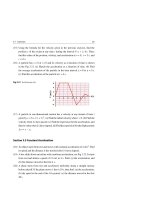
(45) Apply symmetry arguments to the equal-valued resistors of Fig. 24.42 to show
that: (a) the current passing through any resistor in the figure is either I/3 or
I/6. (b) the equivalent resistance of the circuit is 5 R/6.
Fig. 24.42 See Exercise (45)
I
R
R
R
R
S
R
R
R
R
R
R
R
I
R
Section 24.7 The RC Circuit
(46) In the process of charging a capacitor of capacitance C through a resistor
of resistance R, about 63% of the maximum charge will accumulate on the
capacitor in a time t = R C (known as the time constant τ = R C). In this time,
what percentage of the maximum electrostatic energy is stored on the capacitor?
(47) An uncharged capacitor has a capacitance of 2 µF. A battery of 12 V charges
this capacitor through a 1 M resistor. (a) Find the time constant of the circuit,
the maximum charge on the capacitor, and the maximum current in the circuit.
24.8 Exercises
855
(b) How much time is required for the potential difference across the capacitor
to reach 6 V?
(48) Prove that when switch S in Fig. 24.43 is closed, the charge q at time t on any
capacitor is q = Q(1 − e−t/τ ), where τ = (R1 + R2 )(C1 + C2 ) and Q = (C1 +
C2 ) E.
Fig. 24.43 See Exercise (47)
S
R1
C2
C1
R2
(49) A 5 µF capacitor is charged to 220 V. After disconnecting it from its source, a
student holds its two lead wires with his bare hands. Assume that the resistance
between the student’s hands is 50 k . (a) What is the initial charge on the
capacitor and the maximum current that passes through the student’s body? (b)
Find the charge that remains on the capacitor, and calculate the current that
passes through the student’s body after 0.5 s.
(50) The switch in the circuit of Fig. 24.44 is left open for a long time, and then
closed at t = 0. Let R1 = 50 k , R2 = 150 k , C = 5 µF, and E = 30 V. Find
the time constant before and after the switch is closed. Then find the current in
the switch as a function of time.
Fig. 24.44 See Exercise (50)
S
C
R1
R2
Part VI
Magnetism
25
Magnetic Fields
It is of common knowledge that every magnet attracts pieces of iron and has two
poles: a north pole (N) and a south pole (S). In addition, given two magnets, like
poles (N–N or S–S) repel each other, and opposite poles (N–S) attract each other.
Moreover, if we cut a magnet in half, we do not obtain isolated north and south poles.
Instead, we get two magnets, each with its own north and south pole.
In 1819, Oersted observed the deflection of a pivoted magnet when it was in the
vicinity of a current-carrying wire. Now, it is known that all magnetic phenomena
result from forces arising from electric charges in motion. Based on these forces, the
concept of a magnetic field was introduced as a mechanism for exerting a magnetic
force on a moving charge. This is similar to the concept of an electric field surrounding
an electric charge. That is, in the region of space around any moving charge, a
magnetic field is established (as well as an electric field), and this magnetic field
can exert a force on a second moving charge. Consequently, all atoms can exhibit
magnetic effects, due to the motion of their electrons about their nuclei.
In this chapter, we discuss forces that act on moving charges as well as forces that
act on current-carrying conductors in the presence of a magnetic field. We postpone
discussing the sources of such fields.
25.1
Magnetic Force on a Moving Charge
A magnetic field exists at a particular point in space if a force is exerted on a moving
charge at that point. The magnetic field, like the electric field, is a vector quantity
→
→
and historically is denoted by the symbol B . We can define the magnetic field B at
→
any point in terms of the magnetic force FB exerted by the field on a test charge q
H. A. Radi and J. O. Rasmussen, Principles of Physics,
Undergraduate Lecture Notes in Physics, DOI: 10.1007/978-3-642-23026-4_25,
© Springer-Verlag Berlin Heidelberg 2013
859
860
25 Magnetic Fields
→
moving with a velocity v→. If the smaller angle between the two vectors B and v→ is
denoted by θ, then experiments show that:
• FB ∝ |q|vB sin θ
→
→
• FB has the direction of v→ × B if q is positive
→
→
• FB has the direction of −v→ × B if q is negative
In vector form, these results can be written as follows:
→
→
i
→
→
j
→
k
FB = q v→ × B = q vx vy vz
(25.1)
Bx By Bz
Therefore, the magnitude of the magnetic force on q is:
FB = |q| vB sin θ
→
(25.2)
→
To find the direction of v→ × B and the direction of FB for both positive and negative
q, we use the right-hand rule, as shown in Fig. 25.1.
×B
FB
+
θ
θ
+ q
B
B
B
(a)
θ
(b)
− q
FB
(c)
→
Fig. 25.1 (a) With the right-hand rule, the direction of the thumb points in the direction of →
v × B when
→
→
→
the fingers curl →
v into B . (b) When q is positive, the direction of F B has the same sign as →
v × B . (c)
→
→
→
When q is negative, the directions of F B is opposite to v × B
Equation 25.1 indicates that:
→
• FB = 0
(when v→// B and, of course, when v = 0)
• FB |max = q vB
(when v→⊥ B )
→
• FB ⊥ v→ at all times,
→
→
(hence B changes only the direction of v→)
25.1 Magnetic Force on a Moving Charge
861
From Eq. 25.1, we see that the SI unit for B is newton per coulomb-meter per
second, which is called tesla (T). With the use of the SI unit: 1 ampere is 1 coulomb
per second, so we have:
1T = 1
N
N
=1
C.m/s
A.m
(25.3)
An earlier non-SI unit of B, still in common use, is gauss (G), and is related to tesla
through the conversion formula:
1 T = 104 G
(25.4)
Table 25.1 lists some approximate values of B in a few situations.
Table 25.1 Some approximate values of the magnetic fields
Source of the field
Value of B(T)
New kind of neutron star called a “Magnetar”
1011
Neutron star
108
Superconducting magnet
30
Strong magnet
2
Medical MRI unit
1.5
Small bar magnet
10−2
Surface of the earth
10−4
Inside human brain
10−13
Smallest value in a magnetically shielded room
10−14
For convenience, we label the magnetic field coming out of the page by black dots
(or blue dots), as shown in Fig. 25.2a and the magnetic field going into the page by
black crosses (or blue crosses), as shown in Fig. 25.2b. The same approach is used
for both v→ and I but sometimes with different colors.
Fig. 25.2 Magnetic field
lines: (a) coming out of the
page are indicated by dots, (b)
going into the page are
indicated by crosses
B out of page
(a)
.....
.....
.....
.....
B into page
(b)
×××××
×××××
×××××
×××××
862
25 Magnetic Fields
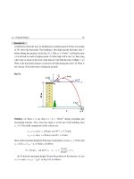
Example 25.1
An electron in a television tube moves along the x-axis with a speed v of 107 m/s,
see the sketch in Fig. 25.3. A uniform magnetic field in the xy plane has a magnitude 0.02 T and is directed at an angle of 30◦ from the x-axis. (a) Calculate the
magnitude of the magnetic force on the electron. (b) Find the vector expression of
→ →
→
the magnetic force on the electron in terms of the unit vectors i , j , and k along
x, y, and z axes.
Fig. 25.3
y
B
z
.
θ
x
Region
of B
Solution: (a) using Eq. 25.2 we find that:
FB = |q| vB sin θ = (1.6 × 10⁻¹⁹ C)(107 m/s)(0.02 T)(sin 30◦ ) = 1.6 × 10⁻¹⁴ N
(b) We first express the velocity and the magnetic field in terms of the unit
→ →
→
vectors i , j , and k as follows:
→
v→ = (107 i ) m/s
→
→
→
B = B cos θ i + B sin θ j
→
→
= [(0.02)(cos 30◦ ) i + (0.02)(sin 30◦ ) j ] T
→
→
= (0.017 i + 0.01 j ) T
We use Eq. 25.1 to find the force on the electron as follows:
→
→
→
k
→
i
→
k
FB = q v→ × B = q vx vy vz = (−e) 107 m/s 0
0
→
j
→
j
→
i
0.017 T 0.01 T 0
Bx By Bz
→
→
→
= (−e) (0) i − (0) j + (107 m/s)(0.01 T) k
→
= (−1.6 × 10⁻¹⁹ C)(105 T m/s) k
→
= −(1.6 × 10⁻¹⁴ N) k
25.1 Magnetic Force on a Moving Charge
863
→
The magnetic force on the electron FB has a magnitude that agrees with the result
of part (a) and is directed along the negative z-axis.
25.2
Motion of a Charged Particle in a Uniform Magnetic Field
→
→
The fact that FB ⊥ v→ indicates that the magnetic field B does not work on the charged
→
particle. Therefore, FB never changes the magnitude of v→, but only changes its
direction.
Let us consider a uniform magnetic field (coming out of the page). Now assume a
positively charged particle q moving with an initial velocity vector v→ perpendicular
to the field, as shown in Fig. 25.4. As the direction of the particle’s velocity changes in
→
response to the magnetic force, the new FB at the new location remains perpendicular
to the new direction of the particle. As a result, the path of the particle is a circle of
radius r. The particle rotates in a clockwise sense if its charge is positive, as shown
in Fig. 25.4, and in a counterclockwise sense if the charge is negative.
Fig. 25.4 When the initial
q
velocity of a positively charged
particle is perpendicular to the
B
+
FB
r
+
magnetic field, the particle’s
orbit is a circle
q+
FB
FB
q
When we equate the magnitude of the magnetic force, FB = qvB, to the product
of the mass of the particle m and the magnitude of the centripetal acceleration, we
get:
FB = qvB = m ×
v2
r
(25.5)
Solving for r, we get:
r=
mv
qB
(25.6)
864
25 Magnetic Fields
That is, the radius of curvature is proportional to the magnitude of the momentum
mv of the particle and inversely proportional to the magnitude of the charge and to
the magnitude of the magnetic field.
The period of the motion T = 2π r/v, the frequency f = 1/T , and the angular
frequency ω = 2π/T , can be written as:
T=
2π m
qB
(25.7)
f =
qB
2π m
(25.8)
qB
m
(25.9)
ω=
These equations show that T, f, and ω are independent of the speed v of the particle
and the radius r of the orbit.
If the velocity of the charged particle has two components, one perpendicular (v⊥ )
to the uniform magnetic field and the other parallel (v ) to it, then the particle will
→
move in a helical path about the direction of the magnetic field B . For example, if
→
B is along the x-axis, the perpendicular component v⊥ (in the yz plane) determines
the radius of the helix r = mv⊥ /qB, while the parallel component determines the
distance between the turns of the helix (the pitch) p = v T , see Fig. 25.5.
Fig. 25.5 When the initial
y
velocity of a positively
⊥
charged particle has a
component parallel to the
→
magnetic field B , the particle
will move in a helical path
about the direction of the field
O
r
q +
B
x
z
p= T
Example 25.2
A proton of mass m = 1.67 × 10⁻²⁷ kg and charge q = e = 1.6 × 10⁻¹⁹ C is moving in a circular orbit of radius r = 20 cm perpendicular to a uniform magnetic
field of magnitude B = 0.25 T. (a) Find the period of the proton. (b) Find the speed
of the proton. (c) Find the magnitude of the magnetic force on the proton.