Hafez a radi, john o rasmussen auth principles of physics for scientists and engineers 2 36
Bạn đang xem bản rút gọn của tài liệu. Xem và tải ngay bản đầy đủ của tài liệu tại đây (1.03 MB, 30 trang )
25.2 Motion of a Charged Particle in a Uniform Magnetic Field
865
Solution: (a) From Eq. 25.7, we have:
T=
2π m
2π(1.67 × 10⁻²⁷ kg)
=
= 2.6 × 10⁻⁷ s
eB
(1.6 × 10⁻¹⁹ C)(0.25 T)
(b) Using the relation T = 2π r/v [or Eq. 25.6], we have:
v=
2π r
2π(0.2 m)
=
= 4.8 × 10⁶ m/s
T
2.6 × 10⁻⁷ s
(c) From the relation FB = |q|vB sin 90◦ , we have:
FB = evB = (1.6 × 10⁻¹⁹ C)(4.8 × 10⁶ m/s)(0.25 T) = 1.9 × 10⁻¹³ N
Example 25.3
An electron of mass m = 9.11 × 10⁻³¹ kg is moving with a speed v = 2.8 ×
106 m/s. The electron enters a uniform magnetic field of magnitude B = 5 × 10⁻⁴ T
→
when the angle between v→ and B is 60◦ . Find the radius and pitch of the helical
path taken by the electron.
→
Solution: The components v⊥ and v with respect to B are:
v⊥ = v sin θ = (2.8 × 10⁶ m/s) sin 60◦ = 2.42 × 10⁶ m/s
v = v cos θ = (2.8 × 10⁶ m/s) cos 60◦ = 1.40 × 10⁶ m/s
Using the relations r = mv⊥ /qB and p = v T , we have:
r=
(9.11 × 10⁻³¹ kg)(2.42 × 10⁶ m/s)
mv⊥
=
= 0.0276 m = 2.76 cm
eB
(1.6 × 10⁻¹⁹ C)(5 × 10⁻⁴ T)
p=v T =v
25.3
2π r
2π(0.0276 m)(1.4 × 10⁶ m/s)
= 0.1003 m = 10.03 cm
=
v⊥
(2.42 × 10⁶ m/s)
Charged Particles in an Electric and Magnetic Fields
→
→
→
In the presence of both an electric field E and a magnetic field B , the total force F
exerted on a charge q moving with velocity v→ is:
→
→
→
F = q E + qv→ × B
which is often called the Lorentz force.
(25.10)
866
25 Magnetic Fields
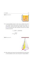
25.3.1 Velocity Selector
Sometimes it is required to select charged particles moving only with same constant
→
velocity. This can be achieved by applying an upward electric field E perpendicular
→
to a magnetic field B coming out of the page, as shown in Fig. 25.6. In this figure
a positive charge q passes from the source through slits S1 and S2 and moves to the
→
right in a straight line with velocity v→. Consequently, the electric force q E points
→
upwards with a magnitude qE, while the magnetic force qv→ × B points downwards
with a magnitude qvB.
E
Source
-
-
-
q
S1 S2
+
+
-
-
+
+
B
+
+
→
qE
+ q
q ×B
→
Fig. 25.6 In a velocity selector, the magnetic field B , electric field E , and the velocity →
v of the charged
→
→
particle are perpendicular to each other. When the magnetic force q→
v × B cancels the electric force qE ,
the charged particle will move in a straight line
→
→
If we choose the values of E and B such that qE = q vB, then:
v=
E
B
(25.11)
and the particle will continue moving in a horizontal straight line through the region
→
→
of the fields. For the chosen values of E and B , all particles with speeds greater than
v = E/B will move downwards, while all particles with speeds less than v = E/B will
move upwards.
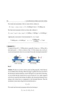
25.3.2 The Mass Spectrometer
A mass spectrometer is an instrument used to measure the mass or the mass-tocharge ratio for charged particles (or ions). The mass spectrometer of Fig. 25.7 has
a source of charged particles behind S1 , and these particles pass through S1 and S2
into a velocity selector like the one shown in Fig. 25.6. Particles that have a speed
of v = E/B pass through slit S3 and enter a deflecting chamber of uniform magnetic
25.3 Charged Particles in an Electric and Magnetic Fields
→
867
→
field B that has the direction of B in the velocity selector. In this region the particles
move in a circular path of radius r.
B′
Plate
+
r
E
Source
- . .- . - . -. . -
. . . . . .
. . .q + . . .
. . . . . .
+
S1 S 2
+
+
+
+
S3
B
Fig. 25.7 The schematic drawing of a mass spectrometer. Positively charged particles from the source
→
enter the velocity selector and then into a region where the magnetic field B causes the particle to move
in a semicircle of radius r before striking a plate
From Eq. 25.6, the mass m can be expressed as follows:
m=
qB r
v
(25.12)
Then we use v = E/B, to calculate the ratio m/q as follows:
BB r
m
=
q
E
(25.13)
If the charge q is known, then the mass m of the charged particle can be calculated
in terms of B, B , E, and r.
25.3.3 The Hall Effect
In 1879, Edwin Hall showed that when a current I passes through a strip of metal
→
which is placed perpendicular to a magnetic field B , a potential difference is estab→
lished in a direction perpendicular to both I and B . This phenomenon is known as
Hall effect.
Figure 25.8a shows a thin flat strip of copper connected to a battery. Electrons
flow with drift speed vd opposite to the conventional current I. In Fig. 25.8b we
868
25 Magnetic Fields
→
show that when we apply to the strip a magnetic field B (into the page), electrons
→
→
→
experience an upward transverse magnetic force FM = qv→d × B = −ev→d × B and are
deflected from their previous course. Because electrons cannot escape from the strip,
negative charges accumulate on its upper side, leaving a net positive charge on its
lower side. This separation of charges produces an upward transverse Hall electric
→
→
→
→
field EH that exerts a downward electric force on the electrons FE = q EH = −eEH .
→
Charges accumulate, and EH increases, until the electric force finally cancels the
magnetic force and equilibrium is established.
t
EH
d
I
-
-
-
No magnetic field
+ -
-×
d
×
+
B
-×
-
×
+
-× I
-
EH B
- - - -× - - ×- I
−e ×B
×
(a)
0
Voltmeter
− e EH
×
×
×
+ + + + + + +
×
+
Intermediate case with B
+ -
Final case with B
+ -
I
I
d
-
I
(b)
(c)
Fig. 25.8 (a) A conductor carrying a current I. (b) The situation immediately after applying the magnetic
→
field into the page. Electrons experience an upward magnetic force F M , accumulate on the top surface,
→
→
→
which creates an upward electric field that produces a downward electric force F E . (c) F E cancels F M at
equilibrium
Equating the electric and magnetic forces on an electron gives:
eEH = evd B
⇒
EH = vd B
(25.14)
When d is the width of the strip, the potential difference VH , called the Hall voltage,
across the strip is related to electric field EH by:
VH = EH d
(25.15)
From Eq. 24.6, the drift speed vd is related to the current I by:
I = nevd A
(25.16)
where A = td is the cross-sectional area of the strip. Substituting with EH from
Eq. 25.15 and vd from Eq. 25.16 into Eq. 25.14, we get VH = IB/net. Usually this
result is written as:
25.3 Charged Particles in an Electric and Magnetic Fields
VH = RH
IB
t
where
RH =
869
1
ne
(25.17)
where RH = 1/ne is the Hall coefficient. Equation 25.17 can be used to measure the
magnitude of the magnetic fields and give information about the sign of the charge
carriers and their density.
Example 25.4
The value of the Hall coefficient RH for a copper strip is 5.4 × 10⁻¹¹ m3 /C. The
strip is 2 mm wide and 0.05 mm thick and carries a current I = 100 mA in a
magnetic field B = 1 T, see Fig. 25.8. (a) How large is the Hall voltage across the
strip? (b) Find the magnitude of the Hall electric field.
Solution: (a) From Eq. 25.17, we have:
VH = RH
IB
(100 × 10−3 A)(1 T)
= 5.4 × 10⁻¹¹ m3 /C
= 1.08 × 10⁻⁷ V
t
0.05 × 10⁻³ m
A Hall voltage of 0.108 µV needs a sensitive measuring instrument.
(b) From Eq. 25.15, we have:
EH =
25.4
1.08 × 10⁻⁷ V
VH
=
= 5.4 × 10⁻⁵ V/m
d
2 × 10⁻³ m
Magnetic Force on a Current-Carrying Conductor
A net flow of charges through a wire is represented by a current. Since a magnetic
field exerts a force on a moving charge, then one should expect that it should exert a
force on a wire carrying a current.
• Figure 25.9a showns a horizontal flexible conducting wire carrying no current. In
→
the presence of a uniform magnetic field B directed out of the page, the wire stays
horizontal.
• However, when the wire carries a current in the left direction, as shown in Fig. 25.9b,
the wire deflects upwards.
• Now, if the current direction is reversed, as shown in Fig. 25.9c, the wire deflects
downwards.
870
25 Magnetic Fields
.
.
.
.
I =0
.
.
.
.
.
.
.
.
.
.
.
.
.
.
.
.
B
B
.
.
.
.
FB
.
.
.
.
.
.
.
.
I
I
.
.
.
.
.
.
.
.
.
.
.
.
FB
(c)
(b)
(a)
.
.
.
.
B
Fig. 25.9 A flexible wire is suspended horizontally and passes through a region of uniform magnetic
field. (a) Without current in the wire, the wire stays horizontal. (b) With a left current, the deflection is
upwards. (c) With a right current, the deflection is downwards
Figure 25.10 shows a segment of a horizontal straight wire of length L and cross→
sectional area A, carrying a current I to the left in a uniform magnetic field B out of
the page. First, we consider a conducting electron of charge q = −e drifting to the
right (opposite to the conventional left current I) with a drift speed vd . According to
Eq. 25.2, the magnetic force on this electron has a magnitude evd B and is directed
upwards.
To find the magnitude of the total upward force on this segment of wire, we
multiply the force on one electron by the total number of conducting electrons in the
segment, which is nAL, where n is the number of electrons per unit volume. Thus:
FB = (evd B)nAL
A
I
Conductor
FB
B
-
d
q = −e
L
Fig. 25.10 Force on a moving charge in a current-carrying conductor. The current direction is to the left,
which means that the electrons drift to the right. A magnetic field out of the page causes the electrons and
the wire to be deflected upwards
From Eq. 25.16, the current in the wire is I = nevd A. Then, the magnitude of the
total upward force on this segment of wire will be:
25.4 Magnetic Force on a Current-Carrying Conductor
871
FB = ILB
(25.18)
→
When the uniform magnetic field B is not perpendicular to the straight wire, the
magnetic force is given by a generalization of Eq. 25.18 as follows:
→
→
→
FB = I L × B
(25.19)
→
where L is a length vector that points in the direction of the conventional current I.
If the wire is not straight, we consider a small straight segment of length ds and
apply Eq. 25.19 to calculate the differential force:
→
→
dFB = I d →
s ×B
(25.20)
To calculate the total force on a wire of arbitrary shape, as shown in Fig. 25.11a,
we integrate Eq. 25.20 over the length of the wire as follows:
b
→
FB =
b
→
dFB = I
a
→
d→
s ×B
(25.21)
a
where the current I runs from one endpoint a to another endpoint b.
I
ds
(a)
I
I
b
L′
ds
B
B
(b)
a
→
Fig. 25.11 (a) F B on any curved wire carrying a current I in a uniform magnetic field is equal to the
→
magnetic force on a straight wire of length L from a to b. (b) F B on a closed loop is zero
→
When the magnetic field is uniform, we take B outside the integrand of Eq. 25.21.
Therefore, this equation reduces to:
⎛
⎞
b
→
→
FB = I ⎝ d →
s ⎠×B
(25.22)
a
→
→
When we integrate over →
s , we get a d →
s = L , where L is a length vector directed
from a to b. Therefore, Eq. 25.21 becomes:
b
→
→
→
FB = I L × B
(25.23)
872
25 Magnetic Fields
For a closed loop, see Fig. 25.11b,
→
d→
s = 0 and hence FB = 0.
Therefore, in a uniform magnetic field, we conclude that:
• The net magnetic force on any curved wire carrying a current I flowing
from one endpoint a to another endpoint b is the same as that for a straight
wire carrying the same current from a to b.
• The net magnetic force on any closed loop of a wire carrying a current I
is zero.
Example 25.5
A conducting wire has a linear density ρ = 40 × 10−3 kg/m and carries a current
→
I = 20 A. Assume a magnetic field B perpendicular to the wire; find the minimum
B and its direction in order to suspend the wire (that is to balance its weight) when
the wire: (a) is in a horizontally straight configuration of a length L, (b) is bent
into an upward vertical semicircular arc of radius R.
Solution: (a) Figure 25.12 shows the situations for both cases, with a selected
direction of I. For a minimum magnetic field, the magnetic force must be upwards
in both cases as shown in Fig. 25.12.
B
FB
FB
B
I
I
I
R
mg
mg
a
b
2R
L
Fig. 25.12
In order to suspend the straight wire, the magnetic force FB must equal to the
wire’s weight mg. Since FB = ILB and m = ρL, we have:
FB = mg
⇒
ILB = mg
⇒
ILB = ρLg
25.4 Magnetic Force on a Current-Carrying Conductor
B=
Thus:
873
ρg (40 × 10−3 kg/m)(10 m/s2 )
=
= 0.02 T
I
20 A
which is about 200 times the strength of the earth’s magnetic field.
(b) The magnetic force FB on a semicircular wire of radius R carrying a current
I flowing from the one endpoint a to another endpoint b is the same as the magnetic
force exerted on a straight wire having length L = 2R carrying the same current
from a to b. That is FB = I(2R)B. Since m = ρ(π R) and FB must equal mg, then:
2IRB = πρRg
Thus:
B=
πρg
π × (40 × 10−3 kg/m)(10 m/s2 )
=
= 0.0314 T
2I
2 × 20 A
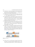
Loudspeakers
The electrical output of a radio or TV set is connected to the leads of a device referred
to as a loudspeaker, which converts electrical energy to sound energy. A loudspeaker
has a permanent magnet that exerts a force on a current-carrying conductor. Those
leads of the speaker are connected internally to a coil that is attached to the speaker
cone, which is made of stiff cardboard that can move freely back and forth in front
of the magnet, see Fig. 25.13.
Fig. 25.13 A sketch showing
a cross-sectional view of a
Rigid metal frame
Coil attached to
speaker cone
typical loudspeaker, where
both the coil and the speaker
freely due to the magnetic
force exerted by the permanent
magnet on the current-carrying
Movable
Speaker
cone
Magnet
S
cone can move back and forth
N
coil
S
I
I
When a current representing an audio signal flows through the coil, the magnetic
field produced by the magnet will exert a force on the coil. As the current varies with
874
25 Magnetic Fields
the frequency of the audio signal, the coil and the speaker cone will move back and
forth with the same frequency. This movement causes compressions and expansions
of the air adjacent to the cone and consequently produces sound waves. As the
electrical input to the speaker varies, the frequency and intensity of the generated
sound waves also change to match.
25.5
Torque on a Current Loop
Most electric motors operate on the principle that a magnetic field exerts a torque on
a loop of a current-carrying conductor. This torque has the ability to rotate the loop
about a fixed rotational axis.
Consider a rectangular loop of two short sides
1
and
2
each of length a and two
long sides 3 and 4 each of length b. The loop carries a current I in the presence
→
of uniform magnetic field B which is always perpendicular to the long sides 3 and
4
, and free to rotate about the axis OO , see Fig. 25.14.
Fig. 25.14 A rectangular
loop carrying a current I that
B
F3
can rotate freely about the axis
O
OO in the presence of a
uniform magnetic field
I F
2
F1
I
b
a
F4
O
In Fig. 25.14, we notice the following:
→
→
• The magnetic forces F1 and F2 on the short sides
1
and
2
cancel each
other and produce no torque, since they pass through a common origin.
→
→
• The magnetic forces F3 and F4 on the long sides 3 and
other, but produce a torque about the rotational axis OO .
4
cancel each
25.5 Torque on a Current Loop
875
→
→
We assume that B makes an angle 0 ≤ θ ≤ 90◦ with the vector area A , which
is a vector perpendicular to the plane of the loop and has a magnitude equal to the
area of the loop, see the side view of the loop shown in Fig. 25.15.
In Fig. 25.15, the side 3 is represented by a circle and the current passing through
it is represented by a red dot, while the side 4 has the current represented by a red
→
→
cross. From Eq. 25.19, the magnitudes of F3 and F4 are the same and given by:
F3 = F4 = IbB
(25.24)
The moment arm of F3 and F4 about O is (a/2) sin θ. Thus, the magnitude of the net
torque about the rotational axis OO is:
τ = F3 (a/2) sin θ + F4 (a/2) sin θ
= [F3 + F4 ](a/2) sin θ = [2IbB](a/2) sin θ
(25.25)
= IAB sin θ
Fig. 25.15 A side view of the
F3
loop showing the two forces
→
A
→
F 3 and F 4 that produce a
torque on the current loop
I
a /2
about point O
B
a sin
2
O
×
I
F4
→
where A = ab is the area of the loop. This equation shows that τmax = IAB when B
→
is perpendicular to the normal of the loop (θ = 90◦ ), and τmin = 0 when B is parallel
to the normal to the plane of the loop (θ = 0).
The direction of the torque exerted on the loop can be expressed in terms of the
vector area as follows:
→
→
τ→ = I A × B
(τ = IAB sin θ )
(25.26)
→
→
(or simply the magThe product I A is defined as the magnetic dipole moment μ
netic moment) of the loop and has the SI unit ampere-meter 2 (A.m2 ). Thus:
876
25 Magnetic Fields
→
→
= IA
μ
(Single loop)
(25.27)
If we replace the single loop of current with a coil of N loops, or turns, then the
→
of the coil will be given by:
magnetic dipole moment μ
→
→
= NI A
μ
(Coil of N loops)
(25.28)
Using this definition, Eq. 25.26 can be written as:
→
→
×B
τ→ = μ
(25.29)
→
→
by using the right-hand rule, which is
We can determine the direction of A and μ
described in Fig. 25.16.
Fig. 25.16 Using the
right-hand rule for determining
→
→for a
the direction of A and μ
μ
I
A
loop of wire carrying a
current I
I
A
μ
25.5.1 Electric Motors
A motor is an apparatus that converts electrical energy into rotational energy. A
battery-powered motor uses the principle of torque exerted on a coil of wire wound
onto a shaft that rotates 360◦ .
In order to allow the coil to continue rotating, the current through the coil must
reverse the direction just as the coil reaches its vertical position. As shown in
Fig. 25.17, several components are required to achieve this reversal. First, an electric
connection is made using two brushes. These are contacts usually made of graphite.
Second, a ring that is split into two halves, called a split-ring commutator. Brushes
make contact with the commutator and allow current to flow into the coil. As the coil
rotates, so does the commutator, which is arranged so that each of its halves changes
brushes just as the coil reaches the vertical position. Changing brushes reverses the
direction of the current in the coil. As a result, the direction of the force on each side
of the coil is reversed and the coil continues to rotate. This process repeats at each
half-turn, causing the coil to spin in the magnetic field.
25.5 Torque on a Current Loop
877
Fig. 25.17 The split-ring
Coil
commutators in an electric
motor allow the current in the
and thus enable the coil in the
Shaft
I
wire coil to change direction
Commutator
motor to rotate continuously
Brush
I
Brush
+
Insulators
Example 25.6
A rectangular coil of sides a = 4 cm and b = 8 cm consists of N = 75 turns of
wire and carries a current I = 10 mA. A magnetic field of magnitude B = 0.2 T is
applied parallel to the plane of the coil, see Fig. 25.18. (a) Find the magnitude of
the magnetic dipole moment of the coil. (b) What is the magnitude of the torque
acting on the coil?
Fig. 25.18
a
I
B
b
I
Solution: (a) Using Eq. 25.28, we have:
μ = NIA = (75)(10 × 10−3 A)[(4 × 10⁻² m)(8 × 10⁻² m)] = 2.4 × 10⁻³ A.m2
→
→
(b) Since B is perpendicular to μ
, then Eq. 25.29 gives:
τ = μB sin 90◦ = (2.4 × 10⁻³ A.m2 )(0.2 T) = 4.8 × 10⁻⁴ N.m
25.5.2 Galvanometers
The basic component of analog ammeters, voltmeters, and ohmmeters is a galvanometer. Figure 25.19 displays the main features of a type of galvanometer called
the D’Arsonval galvanometer. It consists of a coil of wire that has N loops, each of
878
25 Magnetic Fields
cross-sectional area A. That coil is attached to a pointer and a spring. The coil is also
suspended so that it can rotate freely in a radial magnetic field produced by a circular
cross-sectional permanent magnet.
Fig. 25.19 Sketch of the
0
structure of a moving-coil
galvanometer
Scale
φ
Iron core
Pointer
I
S
N
Coil
Spring
When a current I flows through the coil, the magnetic field exerts a torque on the
coil given by Eq. 25.29, and this torque has a magnitude given by:
τ = μB = NIAB
(25.30)
This torque is opposed by the torque τs exerted by the spring, which is approximately
proportional to the coil deflecting angle φ. That is:
τs = k φ
(25.31)
where k is the stiffness constant of the spring. When the pointer is in equilibrium,
we have τs = τ, and we get:
φ=
NAB
I
k
or
φ∝I
(25.32)
Thus, the angular deflection φ of the pointer is directly proportional to the current I
in the coil.
25.6
Non-Uniform Magnetic Fields
One of the useful types of non-uniform magnetic fields is the “magnetic bottle” shown
in Fig. 25.20a. Such magnetic bottles can be used to trap charged particles, because
the magnetic field is strong at the ends and weak in the middle. Charged particles
spiral along the field lines back and forth almost indefinitely if they do not collide.
25.6 Non-Uniform Magnetic Fields
879
Therefore, this magnetic bottle can be used to confine a plasma (a gas consisting of
electrons and ions). Such a confinement can help control nuclear fusion, a process
that could supply us with energy indefinitely.
South magnetic pole
Van Allen belt
North geographic pole
S
N
South geographic pole
(a)
North magnetic pole
(b)
Fig. 25.20 (a) Trapping of charged particles in a non-uniform magnetic bottle. (b) A sketch of the Van
Allen belt, which consists of charged particles trapped by Earth’s non-uniform magnetic field
The Earth behaves like a gigantic magnet. Its north magnetic pole is actually
near the geographic south pole, and its south magnetic pole is near the geographic
north pole, see Fig. 25.20b. This non-uniform magnetic field traps charged particles
(mostly electrons and protons) in a region of space known as Van Allen belt. In this
belt, charged particles spiral around the field lines from pole to pole in a period of few
seconds. The sun and stars are the sources of these particles (called cosmic rays).
Most cosmic rays are deflected by the Earth’s magnetic field and never reach the
atmosphere. When some particles of the Van Allen belt are close to the poles, they
collide with the atoms of the atmosphere causing them to emit light (Aurora Borealis
or Aurora Australis).
25.7
Exercises
Section 25.1 Magnetic Force on a Moving Charge
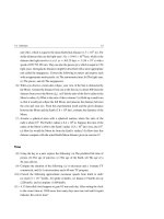
(1) For each of the moving charges shown in Fig. 25.21, find the direction of the
→
magnetic force, taking v→to be the velocity of the particle and B to be the magnetic field.
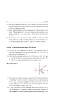
(2) Consider a uniform magnetic field directed vertically up along the page of this
paper. In which direction does an electron deflect if its velocity is directed: (a)
into the paper, (b) up along the paper, (c) to the left, and (d) out of the paper.
880
25 Magnetic Fields
+
-
×B× × × ×
××+
×××
×××××
×××××
(a)
(b)
(c)
B
B
×B× × × ×
× × ×- × ×
×××××
×××××
(d)
B
B
+
B
(e)
-
+
-
(f)
(g)
(h)
B
Fig. 25.21 See Exercise (1)
(3) When moving with a speed of 107 m/s in a magnetic field of magnitude 1.5 T,
an electron experiences a magnetic force of magnitude 10−12 N. What is the
angle between the electron’s velocity and the field at this instant?
→
→
(4) A proton that has a velocity v→ = (3 × 10⁶ i + 4 × 10⁶ j ) (m/s) moves through
→
→
→
a magnetic field B = (0.3 i + 0.02 T j ) (T). Find the vector magnetic force
exerted by the field on the proton, and then find the magnitude and direction of
this force.
(5) Near the Earth’s surface at the equator, the magnetic and electric fields are about
50 µT due North and 100 N/C downwards, respectively. Find the net force on
an electron traveling with velocity 107 m/s due East.
Section 25.2 Motion of a Charged Particle in a Uniform Magnetic Field
(6) In a uniform magnetic field of magnitude of 10−4 T, an ion that has a charge
q = +2e completes two revolutions in 1.51 ms. Find the mass and the type of
the ion.
(7) A proton travels with a speed of 8 × 10⁷ m/s perpendicular to a uniform magnetic
field of magnitude 5 T. (a) What is the radius of the proton’s circular path?
(b) What is the period of the motion? (c) Find the magnitude of the magnetic
force on the proton.
(8) An alpha particle has a charge q = 2 e and mass m
4 mp , where mp is the mass
of a proton. The alpha particle has a kinetic energy of 5 MeV and enters a uniform
magnetic field of 1.5 T directed perpendicular to its velocity. (a) Find the speed
25.7 Exercises
881
of the alpha particle. (b) Find the magnetic force acting on the particle due to
the field. (c) Find the radius of the particle’s path. (d) Find the acceleration of
the particle due the magnetic force.
(9) An electron of speed 5 × 10⁶ m/s enters a uniform magnetic field of magnitude
0.01 T at an angle of 36.87◦ . (a) Determine the radius of the electron’s helical
path. (b) Determine the period of one helical path. (c) Determine the pitch of
the electron’s helical path.
→
(10) Figure 25.22 shows a region of uniform magnetic field B of magnitude 0.5 T
which extends for a width W = 0.4 m. Consider a proton moving with a velocity
→
→
v of magnitude 3 × 10⁷ m/s, where v→ is perpendicular to B . If the incident
angle θ◦ at the lower boundary is 60◦ , the proton emerges from the lower boundary as shown in the left part of the figure. However, if the incident angle θ◦ at the
lower boundary is 0◦ , the proton emerges from the upper boundary as shown in
the right part of the figure. (a) At what angle θ and distance d does the proton exit
from the lower boundary? (b) At what angle θ and distance d does the proton
exit from the upper boundary? (c) At what critical incident angle θ◦ does the
proton barely touch the upper boundary?
d
B
θ
B
W
W
θ°
d
(a)
θ
θ° = 0
(b)
Fig. 25.22 See Exercise (10)
Section 25.3 Charged Particles in Electric and Magnetic Fields
(11) A uniform magnetic field of magnitude 0.02 T is perpendicular to a uniform
electric field of magnitude 750 V/m. What is the speed of an electron that goes
undeflected when moving perpendicular to both fields?
→
→
(12) Assume that a 1 keV electron travels in a uniform electric field E = 385 j
→
→
(kV/m) and a uniform magnetic field B = Bz k . Find the value of Bz such that
882
25 Magnetic Fields
→
the electron would have a velocity v→ = vx i and would move undeflected in
the presence of the two fields.
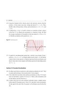
(13) Figure 25.23 shows the path of an electron in a region of uniform magnetic
field. Each of the plates is uniformly charged. (a) Which plate is at the higher
electric potential for each pair? (b) What is the direction of the magnetic field
in this region? (c) For both pairs of plates, if the magnitude of the electric field
between the plates is 6 × 10⁴ V/m and the magnitude of the magnetic field is
2 mT, find the radius of the two semicircles.
Fig. 25.23 See Exercise (13)
Semicircle
Straight
Electron's path
Straight
Semicircle
(14) In the mass spectrometer shown schematically in Fig. 25.6, the magnitude of
the electric and magnetic fields in the velocity-selector region are 3 kV/m and
40 mT, respectively. The magnitude of the magnetic field in the deflecting
chamber is 75 mT. (a) What is the speed of ions in the velocity selector? (b)
What is the radius of the path in the deflecting chamber for a singly-charged
ion having a mass of 6.49 × 10⁻²⁶ kg?
(15) Two single ions of the boron isotopes (of masses 10 u and 11 u) are studied in the mass spectrometer shown schematically in Fig. 25.6. Assume that
the values B = B = 250 mT and E = 60 kV/m are used in this experiment.
(a) What is the speed of the ions in the velocity selector? (b) What is the
spacing between the marks produced on the photographic plate by the ions of
boron?
(16) A strip of copper of thickness t = 0.4 mm and width d = 5 mm is placed in a
→
uniform magnetic field B of magnitude 1.5 T perpendicular to the strip, see
Fig. 25.24. When a current I = 20 A passes though the strip, a Hall potential
difference VH is generated across the width of the strip. The number of charge
carriers per unit volume for copper is 8.47 × 1028 electrons/m3 . (a) Find the
Hall coefficient RH for the copper strip. (b) How large is the Hall voltage VH
across the strip? (c) Find the magnitude of the Hall electric field EH .
25.7 Exercises
883
B
d
I
0
t
Voltmeter
Δ VH
Fig. 25.24 See Exercise (16)
(17) A silver slab of thickness t = 1.5 mm and width d = 2.5 mm carries a current
→
I = 4 A in a region in which there is a uniform magnetic field B of magnitude
1.25 T perpendicular to the slab. The Hall voltage VH across the slab is found
to be 0.356 µV. (a) Calculate the density of the charge carriers in the slab.
(b) Compare your answer in part (a) to the density of atoms in the silver slab,
which has a density ρ = 10.5 × 10³ kg/m3 and a molar mass M = 107.9 kg/kmol.
What is the conclusion that you can find from this comparison? (c) Find the
magnitude of the Hall electric field EH .
(18) A metal strip of thickness t = 1 mm and width d = 2 cm carries a current
→
I = 12.5 A in a region in which there is a uniform magnetic field B of magnitude 1.6 T perpendicular to the strip, as shown in Fig. 25.25. The Hall voltage
VH across the strip is measured to be 2.135 µV. (a) Calculate the drift speed
of the electrons in the strip. (b) Find the density of the charge carriers in the
strip. (c) Which point is at the higher potential, a or b?
Fig. 25.25 See Exercise (18)
B
b
d
t
a
I
884
25 Magnetic Fields
Section 25.4 Magnetic Force on a Current-Carrying Conductor
(19) A 1.5 m long straight stiff wire carries a current of 2 A and makes an angle 30◦
with a uniform magnetic field of 0.35 T. Find the magnitude of the force on the
wire.
(20) The L-shaped wire shown in Fig. 25.26 lies in the xy plane. In the presence of
→
→
a uniform magnetic field B = 1.5 k (T), the wire carries a current of 2.5 A
from point a to point c. (a) Find the net force exerted on the wire. (b) Show that
this net force is the same as if the wire were a straight segment from point a to
point c.
Fig. 25.26 See Exercise (20)
y
c
B
a
4 cm
I
b
3 cm
x
Z
(21) For the circuit shown in Fig. 25.27, find the magnitude and direction of the
force on each side, and find the resultant force.
Fig. 25.27 See Exercise (21)
c
L
B
a
60°
I
b
(22) A straight horizontal wire has a length L = 20 cm and mass m = 0.02 kg. The
wire is hung by connecting it by massless flexible leads to an emf source. A
uniform magnetic field of magnitude B = 1.6 T is perpendicular to the wire, as
shown in Fig. 25.28. Find the necessary current needed to suspend the wire and
hence remove the tension in the flexible wire.
(23) If B = 0.2 T and I = 5 A in Fig. 25.29, find the force exerted on each segment
of the wire.
25.7 Exercises
885
Fig. 25.28 See Exercise (22)
I
Flexible leads
L
B
Fig. 25.29 See Exercise (23)
d
5 cm 60°
c
20 cm
B
I
I
a
10 cm
e
R = 5 cm
10 cm
f
b
(24) A circular loop of wire has a radius R and carries a current I. The loop is
placed in a magnetic field whose lines seem to diverge from a point on the
perpendicular axis of the circular loop and at a distance d from its center, see
Fig. 25.30. Find the total force on the loop.
Fig. 25.30 See Exercise (24)
I
B
N
R
θ
d
I
Section 25.5 Torque on a Current Loop
(25) A circular coil of N = 40 turns has a radius r = 5 cm and carries a current
I = 2 A. The coil is placed in a uniform magnetic field of 0.5 T so that the
→
normal to the coil makes an angle θ = 30◦ with the direction of B . (a) What is
the magnitude of the magnetic moment of the coil? (b) What is the magnitude
of the torque exerted on the coil?
886
25 Magnetic Fields
(26) For the current loop shown in the figure of exercise 21, find: (a) the magnitude
and direction of the loop’s magnetic moment. (b) the magnitude of the torque
on the loop and the direction in which it will rotate.
(27) What is the maximum torque exerted on a 400-turn circular coil of radius 0.5 cm
placed in a uniform magnetic field of magnitude 0.2 T if it carries a current of
1.5 A?
(28) A small, stiff, circular loop of radius R and mass m carries a current I. The loop
lies horizontally on a rough flat table in the presence of a horizontal magnetic
field of magnitude B. (a) What is the required minimum value of B so that one
edge of the loop will lift off the table? (b) What is the required value of B so
that one edge of the loop will lift off the table through an angle θ ?
(29) The 240-turn rectangular coil shown in Fig. 25.31 carries a current of 1.5 A in
a uniform magnetic field of B = 0.25 T. Find the magnitude of the torque on
the loop and the direction in which it will rotate.
Fig. 25.31 See Exercise (29)
c
N
15 cm
d
B
a
S
I
10 cm
b
(30) A rectangular 100-turn coil carries a current I = 1.75 A and has sides a = 40 cm
and b = 30 cm. The coil is hinged along the y-axis, so that its plane makes an
angle θ = 73◦ with the x-axis as shown in Fig. 25.32. (a) What is the magnitude
→
→
of the magnetic moment μ
of the coil? (b) What angle does the vector μ
make
→
→
with the x-axis. (c) In the presence of a uniform magnetic field B = 0.8 i (T),
what is the magnitude of the torque exerted on the coil and what is the expected
direction of the coil’s rotation?
(31) A current I = 0.75 A flows in a quarter of a single circular loop of wire that has
a radius R = 5 cm. The loop lies in the xy plane and is hinged along the y-axis,
so that it can rotate about this axis, see Fig. 25.33. (a) What is the magnitude of
→
→
the magnetic moment μ
of the coil? (b) Express the vector μ
in terms of unit
→
→
→
→
vectors. (c) When a uniform magnetic field B = [0.2 i + 0.3 j + 0.4 k ] (T)
is applied to the loop, express the torque acting on the coil in terms of unit
vectors? In which direction will the loop rotate?
25.7 Exercises
887
Fig. 25.32 See Exercise (30)
y
b
I
x
θ
a
z
Fig. 25.33 See Exercise (31)
y
I
R
x
z
(32) The coil of the galvanometer shown in Fig. 25.34 has N = 35 turns where the
dimensions of each rectangular turn are 2 cm by 2.5 cm. For any position of the
coil, its plane is parallel to the magnetic field which has the value B = 0.4 T.
The galvanometer has a spring with a stiffness constant k = 5 × 10⁻⁶ N.m/rad
and gives a full-scale deflection if the current I going through it is 1 mA. What
is the full-scale deflection angle φ in radians and degrees?
Fig. 25.34 See Exercise (32)
Scale
0
mA
φ
Iron core
1
Pointer
I
S
N
Coil Spring
(33) Assume that the Earth’s magnetic field at the equator is uniform and northerly
directed at all points with a magnitude 5 × 10⁻⁵ T and that it extends out by
888
25 Magnetic Fields
Earth’s diameter (i.e. by 1.28 × 10⁴ km). (a) Find the speed and time that a
singly-ionized uranium atom (m = 238 u, q = +e) would take to circulate the
Earth 20 km above the surface at the equator. (b) A cosmic-ray proton traveling
with a speed of 2.5 × 10⁷ m/s is heading directly towards the center of the Earth
in the plane of the Earth’s equator. Estimate the radius of the proton’s path. Will
the proton hit the Earth?
26
Sources of Magnetic Field
In this chapter we complete the description of magnetic interactions by briefly exploring the origins of magnetic fields.
26.1
The Biot-Savart Law
Based on quantitative experiments, Biot and Savart were able to arrive at a mathematical expression that describes the magnetic field at any point in terms of the
current or the charge that produces the field.
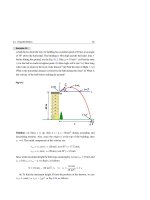
Consider a point P at a distance r from: (a) an element d →
s chosen in the direction
of a steady current I, (b) a point charge q moving with velocity v→, see Fig. 26.1.
Biot and Savart proposed that the magnetic field produced by the element, or by the
charge, would be:
→
dB =
μ◦ I d →
s ×→
rˆ
4π
r2
and
→
B =
μ◦ q v→ × →
rˆ
4π
r2
(Biot-Savart law)
(26.1)
where →
rˆ is a unit vector directed from d →
s or q toward point P. The product I d →
s is
called the differential current element, and μ◦ is a constant called the permeability
of free space’ which has the exact value:
μ◦ = 4π × 10−7 T.m/A
H. A. Radi and J. O. Rasmussen, Principles of Physics,
Undergraduate Lecture Notes in Physics, DOI: 10.1007/978-3-642-23026-4_26,
© Springer-Verlag Berlin Heidelberg 2013
(26.2)
889