Thiết kế dầm sàn dự ứng lực (công ty VSL)
Bạn đang xem bản rút gọn của tài liệu. Xem và tải ngay bản đầy đủ của tài liệu tại đây (3.68 MB, 44 trang )
POST-TENSIONED
SLABS
Fundamentals of the design process
Ultimate limit state
Serviceability limit state
Detailed design aspects
Construction Procedures
Preliminary Design
Execution of the calculations
4.2
VSL REPORT SERIES
Completed structures
PUBLISHED BY
VSL INTERNATIONAL LTD.
Authors
Dr. P. Ritz, Civil Engineer ETH
P. Matt, Civil Engineer ETH
Ch. Tellenbach, Civil Engineer ETH
P. Schlub, Civil Engineer ETH
H. U. Aeberhard, Civil Engineer ETH
Copyright
VSL INTERNATIONAL LTD, Berne/Swizerland
All rights reserved
Printed in Switzerland
Foreword
representatives we offer to interested parties
throughout the world our assistance end
support in the planning, design and construction
of posttensioned buildings in general and posttensioned slabs in particular.
I would like to thank the authors and all those
who in some way have made a contribution to
the realization of this report for their excellent
work. My special thanks are due to Professor Dr
B. Thürlimann of the Swiss Federal Institute of
Technology (ETH) Zürich and his colleagues,
who were good enough to reed through and
critically appraise the manuscript.
With the publication of this technical report, VSL
INTERNATIONAL LTD is pleased to make a
contribution to the development of Civil
Engineering.
The research work carried out throughout the
world in the field of post-tensioned slab
structures and the associated practical
experience have been reviewed and analysed
in order to etablish the recommendations and
guidelines set out in this report. The document
is intended primarily for design engineers,
but we shall be very pleased if it is also of use
to contractors and clients. Through our
Hans Georg Elsaesser
Chairman of the Board and President
If VSLINTERNATIONALLTD
Berne, January 1985
Table of contents
1. lntroduction
1.1. General
1.2. Historical review
1.3. Post-tensioning with or
without bonding of tendons
1.4. Typical applications of
post-tensioned slabs
2. Fundamentals of the design process
2.1. General
2.2. Research
2.3. Standards
Page
2
2
2
3
4
6
6
6
6
3. Ultimate limit state
3 1 Flexure
3.2 Punching shear
6
6
9
4. Serviceability limit state
41 Crack limitation
42. Deflections
43 Post-tensioning force in
the tendon
44 Vibrations
45 Fire resistance
4Z Corrosion protection
11
11
12
12
13
13
13
5. Detail design aspects
5.1. Arrangement of tendons
5.2. Joints
6.Construction procedures
6.1.General
6.2. Fabrication of the tendons
6.3.Construction procedure for
bonded post-tensioning
6.4.Construction procedure for
unbonded post-tensioning
Page
13
13
16
16
16
16
17
7. Preliminary design
19
8. Execution of the calculations
8.1. Flow diagram
8.2. Calculation example
20
20
20
9. Completed structures
9.1.Introduction
9.2.Orchard Towers, Singapore
9.3. Headquarters of the Ilford Group,
Basildon, Great Britain
9.4.Centro Empresarial, São Paulo,
Brazil
26
26
26
28
28
Page
9.5. Doubletree Inn, Monterey,
California,USA
9.6. Shopping Centre, Burwood,
Australia
9.7. Municipal Construction Office
Building, Leiden,Netherlands
9.8.Underground garage for ÖVA
Brunswick, FR Germany
9.9. Shopping Centre, Oberes Murifeld/Wittigkooen, Berne,
Switzerland
9.10. Underground garage Oed XII,
Lure, Austria
9.11. Multi-storey car park,
Seas-Fee, Switzerland
9.12. Summary
30
30
31
32
33
35
35
37
10. Bibliography
38
Appendix 1: Symbols/ Definitions/
Dimensional units/
Signs
39
Appendix 2: Summary of various
standards for unbonded post-tensioning
41
1
1. Introduction
1.1. General
Post-tensioned construction has for many
years occupied a very important position,
especially in the construction of bridges and
storage tanks. The reason for this lies in its
decisive
technical
and
economical
advantages.
The most important advantages offered by
post-tensioning may be briefly recalled here:
- By comparison with reinforced concrete, a
considerable saving in concrete and steel
since, due to the working of the entire
concrete cross-section more slender
designs are possible.
- Smaller deflections than with steel and
reinforced concrete.
- Good crack behaviour and therefore
permanent protection of the steel against
corrosion.
- Almost unchanged serviceability even
after considerable overload, since
temporary cracks close again after the
overload has disappeared.
- High fatigue strength, since the amplitude
of the stress changes in the prestressing
steel under alternating loads are quite
small.
For the above reasons post-tensioned
construction has also come to be used in
many situations in buildings (see Fig 1).
The objective of the present report is to
summarize the experience available today
in the field of post-tensioning in building
construction and in particular to discuss
the design and construction of posttensioned slab structures, especially posttensioned flat slabs*. A detailed
explanation will be given of the checksto
be carried out, the aspects to be
considered in the design and the
construction procedures and sequences
of a post-tensioned slab. The execution of
the design will be explained with reference
to an example. In addition, already built
structures will be described. In all the
chapters, both bonded and unbundled
post-tensicmng will be dealt with.
In addition to the already mentioned general
features of post-tensioned construction, the
following advantages of post-tensioned slabs
over reinforced concrete slabs may be listed:
- More economical structures resulting
from the use of prestressing steels with a
very high tensile strength instead of
normal reinforcing steels.
- larger spans and greater slenderness
(see Fig. 2). The latter results in reduced
dead load, which also has a beneficial
effect upon the columns and foundations
and reduces the overall height of
buildings or enables additional floors to
be incorporated in buildings of a given
height.
- Under permanent load, very good
behavior in respect of deflectons and
crackIng.
- Higher punching shear strength
obtainable by appropriate layout of
tendons
- Considerable reduction In construction
time as a result of earlier striking of
formwork real slabs.
* For definitions and symbols refer to appendix 1.
2
Figure 1. Consumption of prestressing steel in the USA (cumulative curves)
Figure 2: Slab thicknesses as a function of span lengths (recommended limis slendernesses)
1.2. Historical review
Although some post-tensioned slab
structures had been constructed in Europe
quite early on, the real development took
place in the USA and Australia. The first posttensioned slabs were erected in the USA In
1955, already using unbonded posttensioning. In the succeeding years
numerous post-tensioned slabs were
designed and constructed in connection with
the lift slab method. Post-tensionmg enabled
the lifting weight to be reduced and the
deflection and cracking performance to be
improved. Attempts were made to improve
knowledge In depth by theoretical studies and
experiments on post-tensioned plates (see
Chapter 2.2). Joint efforts by researchers,
design engineers and prestressing firms
resulted in corresponding standards and
recommendations and assisted in promoting
the widespread use of this form of
construction in the USA and Australia. To
date, in the USA alone, more than 50 million
m2 of slabs have been post tensioned.
In Europe. renewed interest in this form of
construction was again exhibited in the early
seventies Some constructions were
completed at that time in Great Britain, the
Netherlands and Switzerland.
Intensive research work, especially in
Switzerland, the Netherlands and Denmark
and more recently also in the Federal
Republic of Germany have expanded the
knowledge available on the behaviour of
such structures These studies form the basis
for standards, now in existence or in
preparation in some countries. From purely
empirical beginnings, a technically reliable
and economical form of constructon has
arisen over the years as a result of the efforts
of many participants. Thus the method is now
also fully recognized in Europe and has
already found considerable spreading
various countries (in the Netherlands, in
Great Britain and in Switzerland for example).
Figure 3: Diagrammatic illustration of the extrusion process
1.3. Post-tensioning with or
without bonding of tendons
1.3.1. Bonded post-tensioning
As is well-known, in this method of posttensioning the prestressing steel is placed In
ducts, and after stressing is bonded to the
surrounding concrete by grouting with
cement suspension. Round corrugated ducts
are normally used. For the relatively thin floor
slabs of buildings, the reduction in the
possible eccentricity of the prestressing steel
with this arrangement is, however, too large,
in particular at cross-over points, and for this
reason flat ducts have become common (see
also Fig. 6). They normally contain tendons
comprising four strands of nominal diameter
13 mm (0.5"), which have proved to be
logical for constructional reasons.
Figure 4: Extrusion plant
Figure 5: Structure of a plastics-sheathed,
greased strand (monostrantd)
1.32. Unbonded post-tensioning
In the early stages of development of posttensioned concrete in Europe, posttensioning without bond was also used to
some extent (for example in 1936/37 in a
bridge constructed in Aue/Saxony [D]
according to the Dischinger patent or in 1948
for the Meuse, Bridge at Sclayn [B] designed
by Magnel). After a period without any
substantial applications, some important
structures have again been built with
unbonded post-tensioning in recent years.
In the first applications in building work in the
USA, the prestressing steel was grassed and
wrapped in wrapping paper, to facilitate its
longitudinal movement during stressing
During the last few years, howeverthe
method described below for producing the
sheathing has generally become common.
The strand is first given a continuous film of
permanent corrosion preventing grease in a
continuous operation, either at the
manufacturer’s works or at the prestressing
firm. A plastics tube of polyethylene or
polypropylene of at least 1 mm wall thickness
is then extruded over this (Fig. 3 and 4). The
plastics tube forms the primary and the
grease the secondary corrosion protection.
Strands sheathed in this manner are known
as monostrands (Fig. 5). The nominal
diameter of the strands used is 13 mm (0.5")
and 15 mm (0.6"); the latter have come to be
used more often in recent years.
1.3.3. Bonded or unbonded?
This question was and still is frequently the
subject of serious discussions. The subject
will not be discussed in detail here, but
instead only the most important arguments
far and against will be listed:
Arguments in favour of post-tensioning
without bonding:
- Maximum possible tendon eccentricities,
since tendon diameters are minimal; of
special importance in thin slabs (see Fig
6).
- Prestressing steel protected against
corrosion ex works.
- Simple and rapid placing of tendons.
- Very low losses of prestressing force due
to friction.
- Grouting operation is eliminated.
- In general more economical.
Arguments for post-tensioning with bonding:
- Larger ultimate moment.
- Local failure of a tendon (due to fire,
explosion, earthquakes etc.) has only
limited effects
Whereas in the USA post-tensioning without
bonding is used almost exclusively, bonding
is deliberately employed in Australia.
Figure 6 Comparison between the eccentricities that can be attained with various types of
tendon
3
Among the arguments for bonded posttensioning, the better performance of the
slabs in the failure condition is frequently
emphasized. It has, however, been
demonstrated that equally good structures
can be achieved in unbonded posttensioning by suitable design and detailing.
It is not the intention of the present report to
express a preference for one type of posttensioning or the other. II is always possible
that local circumstances or limiting
engineering conditions (such as standards)
may become the decisive factor in the
choice. Since, however, there are reasons for
assuming that the reader will be less familiar
with undonded post-tensioning, this form of
construction is dealt with somewhat more
thoroughly below.
1.4.
Typical applications of
post-tensioned slabs
As already mentioned, this report is concerned exclusively with post-tensioned slab
structures. Nevertheless, it may be pointed
out here that post-tensioning can also be of
economic interest in the following
components of a multi-storey building:
- Foundation slabs (Fig 7).
- Cantilevered structures, such as
overhanging buildings (Fig 8).
- Facade elements of large area; here light
post-tensioning is a simple method of
preventing cracks (Fig. 9).
- Main beams in the form of girders, lattice
girders or north-light roofs (Fig. 10 and 11).
Typical applications for post-tensioned slabs
may be found in the frames or skeletons for
office buildings, mule-storey car parks,
schools, warehouses etc. and also in multistorey flats where, for reasons of internal
space, frame construction has been selected
(Fig. 12 to 15).
What are the types of slab system used?
- For spans of 7 to 12 m, and live loads up
2
to approx. 5 kN/m , flat slabs (Fig. 16) or
slabs with shallow main beams running in
one direction (Fig. 17) without column
head drops or flares are usually selected.
- For larger spans and live loads, flat slabs
with column head drops or flares (Fig 18),
slabs with main beams in both directions
(Fig 19) or waffle slabs (Fig 20) are used.
Figure 7: Post-tensioned foundation slab
Figure 9: Post-tensioned facade elements
Figure 8: Post-tensioned cantilevered building
Figure 10: Post-tensioned main beams
Figure 11: Post-tensioned north-light roofs
4
Figure 12: Office and factory building
Figure 13: Multi-storey car park
Figure 14: School
Figure 16: Flat Slab
Figure 15: Multi-storey flats
Figure 17: Slab with main beams in one direction
Figure 18: Flat slab with column head drops
Figure 19: Slab with main beams in both directions
Figure 20: Waffle slab
5
2. Fundamentals of the
design process
2.1. General
2.2. Research
The objective of calculations and detailed
design is to dimension a structure so that it
will satisfactorily undertake the function for
which it is intended in the service state, will
possess the required safety against failure,
and will be economical to construct and
maintain. Recent specifications therefore
demand a design for the «ultimate» and
«serviceability» limit states.
Ultimate limit state: This occurs when the
ultimate load is reached; this load may be
limited by yielding of the steel, compression
failure of the concrete, instability of the
structure or material fatigue The ultimate
load should be determined by calculation as
accurately as possible, since the ultimate
limit state is usually the determining criterion
Serviceability limit state: Here rules must
be complied with, which limit cracking,
deflections and vibrations so that the normal
use of a structure Is assured. The rules
should also result in satisfactory fatigue
strength.
The calculation guidelines given in the
following chapters are based upon this
concept They can be used for flat slabs
with or without column head drops or
flares.
They
can
be
converted
appropriately also for slabs with main
beams, waffle slabs etc.
The use of post-tensioned concrete and thus
also its theoretical and experimental
development goes back to the last century.
From the start, both post-tensioned beam
and slab structures were investigated. No
independent research has therefore been
carried out for slabs with bonded postensioning. Slabs with unbonded posttensioning, on the other hand, have been
thoroughly researched, especially since the
introduction of monostrands.
The first experiments on unhonded posttensioned single-span and multi-span flat
slabs were carried out in the fifties [1], [2].
They were followed, after the introduction of
monostrands, by systematic investigations
into the load-bearing performance of slabs
with unbonded post-tensioning [3], [4], [5],
[6], [7], [8], [9], [10] The results of these
investigations were to some extent embodied
in the American, British, Swiss and German,
standard [11], [12], [13], [14], [15] and in the
FIP recommendations [16].
Various investigations into beam structures
are also worthy of mention in regard to the
development of unbonded post-tensioning
[17], [18], [19], [20],[21], [22], [23].
The majority of the publications listed are
concerned predominantly with bending
behaviour. Shear behaviour and in particular
punching shear in flat slabs has also been
thoroughly researched A summary of
punching shear investigations into normally
reinforced slabs will be found in [24]. The
influence of post-tensioning on punching
shear behaviour has in recent years been the
subject of various experimental and
theoretical investigations [7], [25], [26], [27].
Other research work relates to the fire
resistance of post-tensioned structures,
including bonded and unbonded posttensioned slabs Information on this field will
be found, for example, in [28] and [29].
In slabs with unbonded post-tensioning, the
protection of the tendons against corrosion is
of extreme importance. Extensive research
has therefore also been carried out in this
field [30].
2.3. Standards
Bonded post-tensioned slabs can be
designed with regard to the specifications on
post-tensioned concrete structures that exist
in almost all countries.
For unbonded post-tensioned slabs, on the
other hand, only very few specifications and
recommendations at present exist [12], [13],
[15]. Appropriate regulations are in course of
preparation in various countries. Where no
corresponding national standards are in
existence yet, the FIP recommendations [16]
may be applied. Appendix 2 gives a
summary of some important specifications,
either already in existence or in preparation,
on slabs with unbonded post-tensioning.
3. Ultimate limit state
3.1. Flexure
3.1.1. General principles of calculation
Bonded and unbonded post-tensioned
slabs can be designed according to the
known methods of the theories of elasticity
and plasticity in an analogous manner to
ordinarily reinforced slabs [31], [32], [33].
A distinction Is made between the following methods:
A. Calculation of moments and shear forces
according to the theory of elastimry; the
sections are designed for ultimate load.
B. Calculation and design according to the
theory of plasticity.
Method A
In this method, still frequently chosen today,
moments and shear forces resulting from
applied loads are calculated according to
the elastic theory for thin plates by the
method of equivalent frames, by the beam
method or by numerical methods (finite
differences,finite elements).
6
The prestress should not be considered as
an applied load. It should intentionally be
taken into account only in the determination
of the ultimate strength. No moments and
shear forces due to prestress and therefore
also no secondary moments should be
calculated.
The moments and shear forces due to
applied loads multiplied by the load factor
must be smaller at every section than the
ultimate strength divided by the cross-section
factor.
The ultimate limit state condition to be met
may therefore be expressed as follows [34]:
S ⋅γ f ≤ R
(3.1.)
γm
This apparently simple and frequently
encoutered procedure is not without its
problems. Care should be taken to ensure
that both flexure and torsion are allowed for
at all sections (and not only the section of
maximum loading). It carefully applied this
method, which is similar to the static
method of the theory of plasticity,
gives an ultimate load which lies on the sate
side.
In certain countries, the forces resulting from
the curvature of prestressing tendons
(transverse components) are also treated as
applied loads. This is not advisable for the
ultimate load calculation, since in slabs the
determining of the secondary moment and
therefore a correct ultimate load calculation
is difficult.
The consideration of transverse components
does however illustrate very well the effect of
prestressing in service state. It is therefore
highly suitable in the form of the load
balancing method proposed by T.Y. Lin [35]
for calculating the deflections (see Chapter
4.2).
Method B
In practice, the theory of plasticity, is being
increasingly used for calculation and design
The following explanations show how its
application to flat slabs leads to a stole
ultimate load calculation which will be easily
understood by the reader.
The condition to be fulfilled at failure here is:
(g+q) u ≥ γ
(3.2.)
g+q
where γ=γf . γm
The ultimate design loading (g+q)u divided by
the service loading (g+q) must correspond to a
value at least equal to the safety factor y.
The simplest way of determining the ultimate
design loading (g+q)u is by the kinematic
method, which provides an upper boundary
for the ultimate load. The mechanism to be
chosen is that which leads to the lowest load.
Fig. 21 and 22 illustrate mechanisms for an
internal span. In flat slabs with usual column
dimensions (ξ>0.06) the ultimate load can be
determined to a high degree of accuracy by
the line mechanisms ! or " (yield lines 1-1 or
2-2 respectively). Contrary to Fig. 21, the
negative yield line is assumed for purposes of
approximation to coincide with the line
connecting the column axes (Fig. 23),
although this is kinematically incompatible. In
the region of the column, a portion of the
internal work is thereby neglected, which leads
to the result that the load calculated in this way
lies very close to the ultimate load or below it.
On the assumption of uniformly distributed top
and bottom reinforcement, the ultimate design
loads of the various mechanisms are
compared in Fig. 24.
In post-tensioned flat slabs, the prestressing
and the ordinary reinforcement are not
uniformly distributed. In the approximation,
however, both are assumed as uniformly
distributed over the width I1 /2 + 12 /2 (Fig. 25).
The ultimate load calculation can then be
carried out for a strip of unit width 1. The actual
distribution of the tendons will be in
accordance with chapter 5.1. The top layer
ordinary
reinforcement
should
be
concentrated over the columns in accordance
with Fig. 35.
The load corresponding to the individual
mechanisms can be obtained by the principle
of virtual work. This principle states that, for a
virtual displacement, the sum of the work We
performed by the applied forces and of the
dissipation work W, performed by the internal
forces must be equal to zero.
We +Wi,=0
(3.3.)
If this principle is applied to mechanism !
(yield lines 1-1; Fig. 23), then for a strip of
width I1/2 + 1 2/2 the ultimate design load (g+q)
u is obtained.
internal span:
Figure 21: Line mecanisms
Figure 22: Fan mecanisms
Figure 24: Ultimate design load of the
various mecanisms as function of column
diemnsions
Figure 23: Line mecanisms (proposed
approximation)
Figure 25: Assumed distribution of the
reinforcement in the approximation
method
(g+q)u = 8 . mu . (1+ λ)
2
l
(3.7.)
2
Edge span with cantilever:
7
For complicated structural systems, the
determining mechanisms have to be found.
Descriptions of such mechanisms are
available in the relevant literature, e.g. [31],
[36].
In special cases with irregular plan shape,
recesses etc., simple equilibrium considerations (static method) very often prove to be a
suitable procedure. This leads in the simplest
case to the carrying of the load by means of
beams (beam method). The moment
distribution according to the theory of elasticity
may also be calculated with the help of
computer programmes and internal stress
states may be superimposed upon these
moments. The design has then to be done
according to Method A.
3.12. Ultimate stength of a
cross-section
For given dimensions and concrete qualities,
the ultimate strength of a cross-section is
dependent upon the following variables:
- Ordinary reinforcement
- Prestressing steel, bonded or unbonded
- Membrane effect
The membrane effect is usually neglected
when determining the ultimate strength. In
many cases this simplification constitutes a
considerable safety reserve [8], [10].
The ultimate strength due to ordinary
reinforcement and bonded post-tensioning
can be calculated on the assumption,
which in slabs is almost always valid, that
the steel yields, This is usually true also for
cross-sections over intermediate columns,
where the tendons are highly concentrated.
In bonded post- tensioning, the prestressing
force in cracks is transferred to the concrete
by bond stresses on either side of the crack .
Around the column mainly radial cracks open
and a tangentially acting concrete
compressive zone is formed. Thus the
so-called effective width is considerably
increased [27]. In unbonded post-tensioning,
the prestressing force is transferred to the
concrete by the end anchorages and, by
approximation, is therefore uniformly
distributed over the entire width at the
columns.
Figure 26: ultimate strenght of a
cross-section (plastic moment)
For unbonded post-tensioning steel, the
question of the steel stress that acts in the
ultimate limit state arises. If this steel stress is
known (see Chapter 3.1.3.), the ultimate
strength of a cross-section (plastic moment)
can be determined in the usual way (Fig. 26):
mu =zs. (ds - xc ) + z p. (dp - x c)
2
2
where
z S= AS.fsy
z p= A p.(σp∞ + ∆σp )
(3.10.)
zs + zp
xc =
b . fcd
(3.12.)
(3.11.)
3.1.3. Stress increase in unbonded
post-tensioned steel
Hitherto, the stress increase in the unbonded
post-tensioned steel has either been
neglected [34] or introduced as a constant
value [37] or as a function of the
reinforcement content and the concrete
compressive strength [38].
A differentiated investigation [10] shows that
this increase in stress is dependent both upon
the geometry and upon the deformation of the
entire system. There is a substantial
difference depending upon whether a slab is
laterally restrained or not. In a slab system,
the internal spans may be regarded as slabs
with lateral restraint, while the edge spans in
the direction perpendicular to the free edge or
the cantilever, and also the corner spans are
regarded as slabs without lateral restraint.
In recent publications [14], [15], [16], the
stress increase in the unbonded post-
Figure 27: Tendon extension without lateral restraint
8
(3.9)
tensioned steel at a nominal failure state is
estimated and is incorporated into the
calculation together with the effective stress
present (after losses due to friction, shrinkage,
creep and relaxation). The nominal failure
state is established from a limit deflection au .
With this deflection, the extensions of the
prestressed tendons in a span can be
determined from geometrical considerations.
Where no lateral restraint is present (edge
spans in the direction perpendicular to the free
edge or the cantilever, and corner spans) the
relationship between tendon extension and
the span I is given by:
∆I 4 . au . yp = 3 . au . dp
(3.13.)
=
I
I I
I
I
whereby a triangular deflection diagram and
an internal lever arm of yp = 0.75 • d, is
assumed The tendon extension may easily
be determined from Fig. 27.
For a rigid lateral restraint (internal spans) the
relationship for the tendon extension can be
calculated approximately as
∆I
a .2
. a . hp
=2 . ( u ) + 4 u
I
I
I
I
(3.14.)
Fig. 28 enables the graphic evaluation of
equation (3.14.), for the deviation of which we
refer to [10]
The stress increase is obtained from the
actual stress-strain diagram for the steel and
from the elongation of the tendon ∆I
uniformly distributed over the free length L of
the tendon between the anchorages. In the
elastic range and with a modulus of elasticity
Ep for the prestressing steel, the increase in
steel stress is found to be
∆σp = ∆I . I
I
L
. Ep = ∆I . E p
L
(3.15)
The steel stress, plus the stress increase ∆σp
must, of course, not exceed the yeld strength
of the steel.
In the ultimate load calculation, care must be
taken to ensure that the stress increase is
established from the determining mechanism.
This is illustaced diagrammatically
Figure 28: Tendon extension with rigid lateral restraint
3.2. Punching shear
Figure 29: Determining failure mechanisms for two-span beam
in Fig 29 with reference to a two-span beam.
It has been assumed here that the top layer
column head reinforcement is protruding
beyond the column by at least
Ia min ≥ I . (1 - 1 )
λ
√1 + 2
(3.16)
in an edge span and by at least
Ia min ≥ 1 . (1 − 1 )
2
√1 + λ
(3.17)
in an internal span. It must be noted that Ia min
does not include the anchoring length of the
reinforcement.
In particular, it must be noted that, if I1 = I2 ,
the plastic moment over the internal column
will be different depending upon whether
span 1 or span 2 is investigated.
Example of the calculation of a tendon
extension:
According to [14], which is substantially in
line with the above considerations, the
nominal failure state is reached when with a
determining mechanism a deflection au of
1/40th of the relevant span I is present.
Therefore equations (3.13) and (3.14) for the
tendon extension can be simplified as
follows:
Without lateral restraint, e.g. for edge spans
of flat slabs:
∆I=0.075 . dp
(3.18.)
With a rigid lateral restraint, e g. for internal
spans of flat slabs:
∆I=0.05 . (0.025 . 1 + 2 . hp )
(319.)
Figure 30: Portion of slab in column area; transverse components due to prestress in critical
shear contrary
32.1. General
Punching shear has a position of special
importance in the design of flat slabs. Slabs, which
are practically always under-reinforced against
flexure, exhibit pronounced ductile bending failure.
In beams, due to the usually present shear
reinforcement, a ductile failure is usually assured in
shear also. Since slabs, by contrast, are provided
with punching shear reinforcement only in very
exceptional cases,because such reinforcement is
avoided if at all possible for practical reasons,
punching shear is associated with a brittle failure of
the concrete.
This report cannot attempt to provide generally valid
solutions for the punching problem. Instead, one
possibile solution will be illustrated. In particular we
shall discuss how the prestress can be taken into
account in the existing design specifications, which
have usually been developed for ordinarily
reinforced flat slabs.
In the last twenty years, numerous design formulae
have been developed, which were obtained from
empirical investigations and, in a few practical
cases, by model represtation. The calculation
methods and specifications in most common use
today limit the nominal shear stress in a critical
section around the column in relation to a design
value as follows [9]:
(3.20.)
The design shear stress value Tud is
established from shear tests carried out on
portions of slabs. It is dependent upon the
concrete strength f c’ the bending reinforcement
content pm’, the shear reinforcement content
pv’,the slab slenderness ratio h/l, the ratio of
column dimension to slab thickness ζ, bond
properties and others. In the various
specifications and standards, only some of
these influences are taken into account.
3.2.2. Influence of post tensioning
Post-tensioning can substantially alleviate
the punching shear problem in flat slabs if
the tendon layout is correct.
A portion of the load is transferred by the transverse
components resulting from prestressing directly to
the column. The tendons located inside the critical
shear periphery (Fig. 30) can still carry loads in the
form of a cable system even after the concrete
compressive zone has failed and can thus prevent
the collapse of the slab. The zone in which the
prestress has a loadrelieving effect is here
intentionally assumed to be smaller than the
punching cone. Recent tests [27] have
demonstrated that, after the shear cracks have
appeared, the tendons located outside the crlncal
shear periphery rupture the concrete vertically
unless heavy ordinary reinforcement is present,
and they can therefore no longer provide a loadbearing function.
If for constructional reasons it is not possible to
arrange the tendons over the column within the
critical shear periphery or column strip bck defined
in Fig. 30 then the transfer of the transverse
components resulting
9
from tendons passing near the column
should be investigated with the help of a
space frame model. The distance between
the outermost tendons to be taken into
account for direct load transfer and the edge
of the column should not exceed ds on either
side of the column.
The favourable effect of the prestress can
be taken account of as follows:
1 The transverse component Vp ∞ resulting
from the effectively present prestressing
force and exerted directly in the region of
the critical shear periphery can be
subtracted from the column load resulting
from the applied loads. In the tendons, the
prestressing force after deduction of all
losses and without the stress increase
should be assumed. The transverse
component Vp is calculated from Fig. 30
as
Vp=Σ Pi . ai = P. a
(3.21.)
Here, all the tendons situated within the
critical shear periphery should be
considered, and the angle of deviation
within this shear periphery should be
used for the individual tendons.
2 The bending reinforcement is sometimes
taken into account when establishing the
permissible shear stress [37], [38], [39].
The prestress can be taken into account
by an equivalent portion [15], [16].
However, as the presence of concentric
compression due to prestress in the
column area is not always guaranteed
(rigid walls etc.) it is recommended that
this portion should be ignored.
If punching shear reinforcement must be
incorporated, it should be designed by
means of a space frame model with a
concrete compressive zone in the failure
state inclined at 45° to the plane of the slab,
for the column force 1.8 Vg+q -Vp . Here, the
following condition must be complied with.
2. Rd ≥1.8 . Vg+q -V p
(3.24.)
For punching shear reinforcement, vertical
stirrups are recommended; these must pass
around the top and bottom slab
reinforcement. The stirrups nearest to the
edge of the column must be at a distance
from this column not exceeding 0.5 • ds. Also,
the spacing between stirrups in the radial
direction must not exceed 0.5 • ds (Fig.31).
Slab connections to edge columns and
corner columns should be designed
according to the considerations of the beam
theory. In particular, both ordinary
reinforcement and post-tensioned tendons
should be continued over the column and
properly anchored at the free edge (Fig. 32).
Figure 31: Punching shear reinforcement
3.2.3. Carrying out the calculation
A possible design procedure is shown in [14];
this proof, which is to be demonstrated in the
ultimate limit state, is as follows:
Rd ≥ 1.4 . V
1.3
g+q
- Vp
1.3
(3.22.)
The design value for ultimate strength for
concentric punching of columns through
slabs of constant thickness without
punching shear reinforcement should be
assumed as follows:
Rd = uc . ds . 1.5 .Tud
(3.23.)
Uc is limited to 16 . ds, at maximum and the
ratio of the sides of the rectangle surrounding
the column must not exceed 2:1.
Tud can be taken from Table I.
10
Figure 32: Arrangement of reinforcement at corner and edge columns
4.
Serviceability limit
state
4.1. Crack limitation
4.1.1. General
In slabs with ordinary reinforcement or
bonded post-tensioning, the development of
cracks is dependent essentially upon the
bond characteristics between steel and
concrete. The tensile force at a crack is
almost completely concentrated in the steel.
This force is gradually transferred from the
steel to the concrete by bond stresses. As
soon as the concrete tensile strength or the
tensile resistance of the concrete tensile
zone is exceeded at another section, a new
crack forms.
The influence of unbonded post-tensioning
upon the crack behaviour cannot be
investigated by means of bond laws. Only
very small frictional forces develop between
the unbonded stressing steel and the
concrete. Thus the tensile force acting in the
steel is transferred to the concrete almost
exclusively as a compressive force at the
anchorages.
Theoretical [10] and experimental [8]
investigations have shown that normal forces
arising from post-tensioning or lateral
membrane forces influence the crack
behaviour in a similar manner to ordinary
reinforcement.
In [10], the ordinary reinforcement content p*
required for crack distribution is given as a
function of the normal force arising from
prestressing and from the lateral membrane
force n.
Fig. 33 gives p* as a function of p*, where
p* = pp -
n
dp . σpo
4.12. Required ordinary reinforcement
The design principles given below are in
accordance with [14]. For determining the
ordinary reinforcement required, a distinction
must be made between edge spans, internal
spans and column zones.
Edge spans:
Required ordinary reinforcement (Fig. 34):
ps ≥ 0.15 - 0.50 . pp
(4.2)
Lower limit: ps ≥ 0.05%
Figure 34: Minimum ordinary reinforcement
required as a function of the post-tensioned
reinforcement for edge spans
Internal spans:
For internal spans, adequate crack distribution is in general assured by the post-
tensioning and the lateral membrane
compressive forces that develop with even
quite small deflections. In general, therefore,
it is not necessary to check for minimum
reinforcement. The quantity of normal
reinforcement required for the ultimate limit
state must still be provided.
Column zone:
In the column zone of flat slabs, considerable
additional ordinary reinforcement must
always be provided. The proposal of DIN
4227 may be taken as a guideline, according
to which in the zone bcd = bc + 3 . ds (Fig. 30)
at least 0.3% reinforcement must be
provided and, within the rest of the column
strip (b g = 0.4 . I) at least 0.15% must be
provided (Fig. 35). The length of this
reinforcement including anchor length should
be 0.4 . I. Care should be taken to ensure
that the bar diameters are not too large.
The arrangement of the necessary minimum
reinforcement is shown diagrammatically in
Fig.35. Reinforcement in both directions is
generally also provided everywhere in the
edge spans. In internal spans it may be
necessary for design reasons, such as point
loads, dynamic loads (spalling of concrete)
etc. to provide limited ordinary reinforcement.
Figure 35: Diagrammatic arrangement of minimum reinforcement
(4.1.)
If n is a compressive force, it is to be provided
with a negative sign.
Figure 33: Reinforcement content required
to ensure distribution of cracks
Various methods are set out in different
specifications for the assessment and control
of crack behaviour:
- Limitation of the stresses in the ordinary
reinforcement calculated in the cracked
state [40].
- Limitation of the concrete tensile stresses
calculated for the homogeneous crosssection [12].
- Determination of the minimum quantity of
reinforcement that will ensure crack
distribution [14].
- Checking for cracks by theoretically or
empirically obtained crack formulae [15].
11
4.3. Post-tensioning force in the
tendon
Figure 36: Transverse components and panel forces resulting from post-tensioning
Figure 37: Principle of the load-balancing method
4.2. Deflections
Post-tensioning has a favourable influence
upon the deflections of slabs under service
loads. Since, however, post-tensioning also
makes possible thinner slabs, a portion of this
advantage is lost.
As already mentioned in Chapter 3.1.1., the
load-balancing method is very suitable for
calculating deflections. Fig. 36 and 37
illustrate the procedure diagrammatically.
Under permanent loads, which may with
advantage be largely compensated by the
transverse components from post-tensioning,
the deflections can be determined on the
assumption of uncracked concrete.
Under live loads, however, the stiffness is
reduced by the formation of cracks. In slabs
with bonded post-tensioning, the maximum
loss of stiffness can be estimated from the
normal reinforced concrete theory. In slabs
with unbonded post-tensioning, the reduction
in stiffness, which is very large in a simple
beam reinforced by unbonded posttensioning, is kept within limits in edge spans
by the ordinary reinforcement necessary for
crack distribution,
Figure 38: Diagram showing components of
deflection in structures sensitive to deflections
and in internal spans by the effect of the
lateral restraint.
In the existing specifications, the deflections
are frequently limited by specifying an upper
limit to the slenderness ratio (see Appendix 2).
In structures that are sensitive to deflection,
the deflections to be expected can be
estimated as follows (Fig. 38):
a = ad-u + ag+qr - d + a q-qr
(4.3.)
The deflection ad-u, should be calculated for
the homogeneous system making an
allowance for creep. Up to the cracking load
g+qr ’ which for reasons of prudence should
be calculated ignoring the tensile strength of
the concrete, the deflection ag+qr --d should be
established for the homogeneous system
under short-term loading. Under the
remaining live loading, the deflection aq-qr
should be determined by using the stiffness
of the cracked crosssection. For this
purpose, the reinforcement content from
ordinary reinforcement and prestressing can
be assumed as approximately equivalent,
i.e. p=ps+pp is used.
In many cases, a sufficiently accurate
estimate of deflections can be obtained if
they are determined under the remaining
load (g+q-u) for the homogeneous system
and the creep is allowed for by reduction of
the elastic modulus of the concrete to
EcI = Ec
1+ ϕ
12
4.32. Long-term losses
The long-term losses in slabs amount to
about 10 to 12% of the initial stress in the
prestressing steel. They are made up of the
following components:
Creep losses:
Since the slabs are normally post-tensioned
for dead load, there is a constant
compressive stress distribution over the
cross-section. The compressive stress
generally is between 1.0 and 2.5 N/mm 2 and
thus produces only small losses due to
creep. A simplified estimate of the loss of
stress can be obtained with the final value for
the creep deformation:
∆σpc=εcc . Ep =ϕn . σ c . Ep
Ec
(4.6.)
Although the final creep coefficient ϕn due to
early post-tensioning is high, creep losses
exceeding 2 to 4% of the initial stress in the
prestressing steel do not in general occur.
Shrinkage losses:
The stress losses due to shrinkage are given
by the final shrinkage factor scs as:
∆σps = εcs . E p
(4.7.)
(4.4.)
On the assumption of an average creep
factor ϕ = 2 [41] the elastic modulus of the
concrete should be reduced to
I
Ec =Ec
3
4.3.1. Losses due to friction
For monostrands, the frictional losses are
very small. Various experiments have
demonstrated that the coefficients of friction
µ= 0.06 and k = 0.0005/m can be assumed.
It is therefore adequate for the design to
adopt a lump sum figure of 2.5%
prestressing force loss per 10 m length of
strand. A constant force over the entire length
becomes established in the course of time.
For bonded cables, the frictional coefficients
are higher and the force does not become
uniformly distributed over the entire length.
The calculation of the frictional losses is
carried out by means of the well-known
formula PX = Po . e-( µa +kx). For the coefficients of friction the average values of Table
II can be assumed.
The force loss resulting from wedge drawin
when the strands are locked off in the
anchorage, can usually be compensated by
overstressing. It is only in relatively short
cables that the loss must be directly allowed
for. The way in which this is done is
explained in the calculation example
(Chapter 8.2.).
(4 .5.)
The shrinkage loss is approximately 5% of
the initial stress in the prestressing steel.
Table II - Average values of friction for
bonded cables
Relaxation losses:
The stress losses due to relaxation of the
post-tensioning steel depend upon the type
of steel and the initial stress. They can be
determined from graphs (see [42] for
example). With the very low relaxation
prestressing steels commonly used today, for
an initial stress of 0.7 pu
f and ambient
temperature of 20°C, the final stress loss due
to relaxation is approximately 3%.
Losses due to elastic shortening of the
concrete:
For the low centric compression due to
prestressing that exists, the average stress
loss is only approximately 0.5% and can
therefore be neglected.
4.4. Vibrations
For dynamically loaded structures, special
vibration investigations should be carried out.
For a coarse assessment of the dynamic
behaviour, the inherent frequency of the slab
can be calculated on the assumption of
homogeneous action.
4.5. Fire resistance
In a fire, post-tensioned slabs, like ordinarily
reinforced slabs, are at risk principally on
account of two phenomena: spalling of the
concrete and rise of temperature in the steel.
Therefore, above all, adequate concrete
cover is specified for the steel (see Chapter
5.1.4.).
The fire resistance of post-tensioned slabs is
virtually equivalent to that of ordinarily
reinforced slabs, as demonstrated by
corresponding tests. The strength of the
prestressing steel does indeed decrease more
rapidly than that of ordinary reinforcement as
the temperature rises, but on the other hand in
post-tensioned slabs better protection is
provided for the steel as a consequence of the
uncracked cross-section.
The behaviour of slabs with unbonded posttensioning is hardly any different from that of
slabs with bonded post-tensioning, if the
appropriate design specifications are
followed. The failure of individual unbonded
tendons can, however, jeopardize several
spans. This circumstance can be allowed for
by the provision of intermediate anchorages.
From the static design aspect, continuous
systems and spans of slabs with lateral
constraints exhibit better fire resistance.
An analysis of the fire resistance of
posttensioned slabs can be carried out, for
example, according to [43].
following conditions:
- Freedom from cracking and no embrittlement or liquefaction in the temperature
range -20° to +70 °C
- Chemical stability for the life of the
structure
- No reaction with the surrounding
materials
- Not corrosive or corrosion-promoting
- Watertight
A combination of protective grease coating
and plastics sheathing will satisfy these
requirements.
Experiments in Japan and Germany have
demonstrated that both polyethylene and
polypropylene ducts satisfy all the above
conditions.
As grease, products on a mineral oil base are
used; with such greases the specified
requirements are also complied with.
The corrosion protection in the anchorage
zone can be satisfactorily provided by
appropriate constructive detailing (Fig. 39), in
such a manner that the prestressing steel is
continuously protected over its entire length.
The anchorage block-out is filled with
lowshrinkage mortar.
4.6. Corrosion protection
4.6.1. Bonded post-tensioning
The corrosion protection of grouted tendons
is assured by the cement suspension
injected after stressing. If the grouting
operations are carefully carried out no
problems arise in regard to protection.
The anchorage block-outs are filled with lowshrinkage mortar.
4.62. Unbonded post-tensioning
The corrosion protection of monostrands
described in Chapter 1.3.2. must satisfy the
Figure 39: Corrosion protection in the
anchorage zone
ponent is made equal to the dead load,then
under dead load and prestress a complete
load balance is achieved in respect of
flexure and shear if 50 % of the tendons are
uniformly distributed in the span and 50 %
are concentrated over the columns.
5. Detail design aspects
5.1. Arrangement of tendons
5.1.1. General
The transference of loads from the interior of
a span of a flat slab to the columns by
transverse components resulting from
prestressing is illustrated diagrammatically in
Fig. 40.
In Fig. 41, four different possible tendon
arrangements are illustrated: tendons only
over the colums in one direction (a) or in two
directions (b), the spans being ordinarily
reinforced (column strip prestressing);
tendons distributed in the span and
concentrated along the column lines (c and
d). The tendons over the colums (for column
zone see Fig. 30) act as concealed main
beams.
When selecting the tendon layout, attention
should be paid to flexure and punching and
also to practical construction aspects
(placing of tendons). If the transverse com-
Figure 40: Diagrammatic illustration of load transference by post-tensioning
13
Table III - Required cover of prestressing
steel by concrete (in mm) as a function of
conditions of exposure and concrete grade
1) for example, completely protected against
weather, or aggressive conditions, except for
brief period of exposure to normal weather
conditions during construction.
2) for example, sheltered from severe rain or
against freezing while saturated with water,
buried concrete and concrete continuously under water.
3) for example, exposed to driving rain, alternate
wetting and drying and to freezing while wet,
subject to heavy condensation or corrosive fumes.
Figure 41: Possible tendon arrangements
Under this loading case, the slab is stressed
only by centric compressive stress. In regard
to punching shear, it may be advantageous
to position more than 50 % of the tendons
over the columns.
In the most commonly encountered
cases, the tendon arrangement illustrated
in Fig. 41 (d), with half the tendons in each
direction uniformly distributed in the span
and half concentrated over the columns,
provides the optimum solution in respect
of both design and economy.
5.1.2. Spacings
The spacing of the tendons in the span
should not exceed 6h, to ensure
transmission of point loads. Over the column,
the clear spacing between tendons or strand
bundles should be large enough to ensure
proper compaction of the concrete and allow
sufficient room for the top ordinary
reinforcement. Directly above the column,
the spacing of the tendons should be
adapted to the distribution of the
reinforcement.
In the region of the anchorages, the spacing
between tendons or strand bundles must be
chosen in accordance with the dimensions of
the anchorages. For this reason also, the
strand bundles themselves are splayed out,
and the monostrands individually anchored.
14
5.1.3. Radii of curvature
For the load-relieving effect of the vertical
component of the prestressing forces over
the column to be fully utilized, the point of
inflection of the tendons or bundles should
be at a distance ds/2 from the column edge
(see Fig. 30). This may require that the
minimum admissible radius of curvature be
used in the column region. The extreme fibre
stresses in the prestressing steel must
remain below the yield strength under these
conditions. By considering the natural
stiffness of the strands and the admissible
extreme fibre stresses, this gives a minimum
radius of curvature for practical use of
r = 2.50 m. This value is valid for strands of
nominal diameter 13 mm (0.5") and 15 mm
(0.6").
5.1.4. Concrete cover
To ensure long-term performance, the
prestressing steel must have adequate
concrete cover. Appropriate values are
usually laid down by the relevant national
standards. For those cases where such
information does not exist, the requirements
of the CEB/FI P model code [39] are given in
Table I I I.
The minimum concrete cover can also be
influenced by the requirements of fire
resistance. Knowledge obtained from
investigations of fire resistance has led to
recommendations on minimum concrete
cover for the post-tensioning steel, as can be
seen from Table IV. The values stated should
be regarded as guidelines, which can vary
according to the standards of the various
countries.
For grouted tendons with round ducts the
cover can be calculated to the lowest or
highest strand respectively.
5.2. Joints
The use of post-tensioned concrete and, in
particular, of concrete with unbonded
tendons necessitates a rethinking of some
long accepted design principles. A question
that very often arises in building design is the
arrangement of joints in the slabs, in the
walls and between slabs and walls.
Unfortunately, no general answer can be
given to this question since there are certain
factors in favour of and certain factors
against joints. Two aspects have to be
considered here:
Table IV - Minimum concrete cover for the post-tensioning steel (in mm) in respect of the fire
resistance period required
-
Ultimate limit state (safety)
Horizontal displacements (serviceability
limit state)
5.2.1. Influence upon the ultimate limit
state behaviour
If the failure behaviour alone is considered, it
is generally better not to provide any joints.
Every joint is a cut through a load-bearing
element and reduces the ultimate load
strength of the structure.
For a slab with unbonded post-tensioning,
the membrane action is favourably
influenced by a monolithic construction. This
results in a considerable increase in the
ultimate load (Fig. 42).
5.2.2. Influence upon the serviceability
limit state
In long buildings without joints, inadmissible
cracks in the load-bearing structure and
damage to non load-bearing constructional
elements can occur as a result of horizontal
displacements. These displacements result
from the following influences:
- Shrinkage
- Temperature
- Elastic shortening due to prestress
- Creep due to prestress
The average material properties given in
Table V enable one to see how such damage
occurs.
In a concrete structure, the following average
shortenings and elongations can be
expected:
Shrinkage
∆Ics = -0.25 mm/m
Temperature
∆Ic t = -0.25 mm/m
to+0.15 mm/m
Elastic shortening
(for an average centric prestress of 1.5
N/mmz and Ec=
30 kN/mm2 )
∆Icel = -0.05 mm/m
Creep
∆Icc = - 0.15 mm/m
Figure 42: Influence of membrane action upon load-bearing capacity
These values should be adjusted for the
particular local conditions.
When the possible joint free length of a
structure is being assessed, the admissible
total displacements of the slabs and walls
or columns and the admissible relative
displacements between slabs and walls or
columns should be taken into account.
Attention should, of course, also be paid to
the foundation conditions.
The horizontal displacements can be partly
reduced or prevented during the construction
stage by suitable constructional measures
(such as temporary gaps etc.) without damage
occurring.
Elastic shortening and creep due to
prestress:
Elastic shortening is relatively small. By
subdividing the slab into separate concreting
stages, which are separately post-tensioned,
Table V -Average material properties of various construction materials
In closed buildings, slabs and walls in the
internal rooms are subject to low temperature
fluctuations. External walls and unprotected
roof slabs undergo large temperature
fluctuations. In open buildings, the relative
temperature difference is small. Particular
considerations arise for the connection to the
foundation and where different types of
construction materials are used.
the shortening of the complete slab is
reduced.
Creep, on the other hand, acts upon the
entire length of the slab. A certain reduction
occurs due to transfer of the prestress to the
longitudinal walls.
Shortening due to prestress should be kept
within limits particularly by the centric
prestress not being made too high. It is
recommended that an average centric
prestress of σcpm = 1.5 N/mm2 should be
selected and the value of 2.5 N/mm2 should
not be exceeded. In concrete walls, the
relative shortening between slabs and walls
can be reduced by approximately uniform
prestress in the slabs and walls.
Figure 43: Examples of jointless structures of 60 to 80 m length
Shrinkage:
Concrete always shrinks, the degree of
shrinkage being highly dependent upon the
water-cement ratio in the concrete, the crosssectional dimensions, the type of curing and
the atmospheric humidity. Shortening due to
shrinkage can be reduced by up to about
one-half by means of temporary shrinkage
joints.
Temperature:
In temperature effects, it is the temperature
difference between the individual structural
components and the differing coefficients of
thermal expansion of the materials that are of
greatest importance.
15
5.2.3. Practical conclusions
In slabs of more than 30 m length, a uniform,
«homogeneous» deformation behaviour of
the slabs and walls in the longitudinal
direction should be aimed at. In open
buildings with concrete walls or columns, this
requirement is satisfied in regard to
temperature effects and, provided the age
difference between individual components is
not too great, is also satisfied for shrinkage
and creep.
In closed buildings with concrete walls or
columns, a homogeneous behaviour for
shrinkage and creep should be achieved. In
respect of temperature, however, the
concreted external walls behave differently
form the internal structure. If cooling down
occurs, tensile stresses develop in the wall.
Distribution of the cracks can be ensured by
longitudinal reinforcement. The tensile
stresses may also be compensated for by
post-tensioning the wall.
If, in spite of detail design measures, the
absolute or relative longitudinal deformations
exceed the admissible values, the building
must be subdivided by joints.
Fig. 43 and 44 show, respectively, some
examples in which joints can be dispensed
with and some in which joints are necessary.
6.
Construction
procedures
6.1. General
The construction of a post-tensioned slab is
broadly similar to that for an ordinarily
reinforced slab. Differences arise in the
placing of the reinforcement, the stressing of
the tendons and in respect of the rate of
construction.
The placing work consists of three phases:
first, the bottom ordinary reinforcement of the
slab and the edge reinforcement are placed.
The ducts or tendons must then be
positioned, fitted with supports and fixed in
place. This is followed by the placing of the
top ordinary reinforcement. The stressing of
the tendons and, in the case of bonded
tendons the grouting also, represent
additional construction operations as
compared with a normally reinforced slab.
Since, however, these operations are usually
carried out by the prestressing firm, the main
contractor can continue his work without
interruption.
A feature of great importance is the short
stripping times that can be achieved with
post-tensioned slabs. The minimum period
between concreting and stripping of
formwork is 48 to 72 hours, depending upon
concrete quality and ambient temperature.
When the required concrete strength is
reached, the full prestressing force can
usually be applied and the formwork stripped
immediately afterwards. Depending upon the
16
Figure 44: Examples of structures that must be subdivided by joints into sections of 30 to
40 m length
total size, the construction of the slabs is
carried out in a number of sections.
The divisions are a question of the geometry
of the structure, the dimensions, the
planning, the construction procedure, the
utilization of formwork material etc. The
construction joints that do occur, are
subseqently subjected to permanent
compression by the prestressing, so that the
behaviour of the entire slab finally is the
same throughout.
The weight of a newly concreted slab must
be transmitted through the formwork to slabs
beneath it. Since this weight is usually less
than that of a corresponding reinforced
concrete slab, the cost of the supporting
structure is also less.
6.2. Fabrication of the tendons
6.2.1. Bonded post-tensioning
There are two possible methods of fabricating cables:
- Fabrication at the works of the prestressing
firm
- Fabrication by the prestressing firm on the
site
The method chosen will depend upon the
local conditions. At works, the strands are cut
to the desired length, placed in the duct and,
if appropriate, equipped with dead-end
anchorages. The finished cables are then
coiled up and transported to the site.
anchorages. The finished cables are then
coiled up and transported to the site.
In fabrication on the site, the cables can
either be fabricated in exactly the same
manner as at works, or they can be
assembled by pushing through. In the latter
method, the ducts are initially placed empty
and the strands are pushed through them
subsequently. If the cables have stressing
anchorages at both ends, this operation can
even be carried out after concreting (except
for the cables with flat ducts).
6.22.
Unbonded post-tensioning
The fabrication of monostrand tendons is
usually carried out at the works of the
prestressing firm but can, if required, also be
carried out on site. The monostrands are cut
to length and, if necessary, fitted with the
dead-end anchorages. They are then coiled
up and transported to site. The stressing
anchorages are fixed to the formwork. During
placing, the monostrands are then threaded
through the anchorages.
6.3.
Construction procedure for
bonded post-tensioning
In slabs with bonded post-tensioning, the
operations are normally carried out as
follows:
1. Erection of slab supporting formwork
2. Fitting of end formwork; placing of
stressing anchorages
3. Placing of bottom and edge reinforcement
4. Placing of tendons or, if applicable, empty
ducts* according to placing drawing
5. Supporting of tendons or empty ducts*
with supporting chairs according to
support drawing
6. Placing of top reinforcement
7. Concreting of the section of the slab
8. Removal of end formwork and forms
for the stressing block-outs
9. Stressing of cables according to stressing
programme
10. Stripping of slab supporting formwork
11.Grouting of cables and concreting of
block-outs
* In this case, the stressing steel is pushed
through either before item 5 or before
item 9.
6.4.
Construction procedure for
unbonded post-tensioning
If unbonded tendons are used, the
construction procedure set out in Chapter
6.3. is modified only by the omission of
grouting (item 11).
The most important operations are illustrated
in Figs. 45 to 52. The time sequence is
illustrated by the construction programme
(Fig. 53).
All activities that follow one another directly
can partly overlap; at the commencement of
activity (i+1), however, phase (i-1) must be
completed. Experience has shown that those
activities that are specific to prestressing
(items 4, 5 and 9 in Chapter 6.3.) are with
advantage carried out by the prestressing
firm, bearing in mind the following aspects:
6.4.1. Placing and supporting of tendons
The placing sequence and the supporting of
the tendons is carried out in accordance with
the placing and support drawings (Figs. 54
and 55). In contrast to a normally reinforced
slab, therefore, for a post-tensioned slab two
drawings for the prestressing must be
prepared in addition to the reinforcement
drawings. The drawings for both, ordinary
reinforcement and posttensioning are,
however, comparatively simple and the
number of items for tendons and reinforcing
bars is small.
The sequence in which the tendons are to be
placed must be carefully considered, so that
the operation can take place smoothly.
Normally a sequence allowing the tendons
Figure 53: Construction programme
Table VI-Achievable accuracies in placing
Direction
column
strip
Vertical
± 5mm
Horizontal
± 20 mm
Remaining
area
± 5mm
± 50 mm
17
to be placed without «threading» or
«weaving» can be found without any
difficulty. The achievable accuracies are
given in Table VI.
To assure the stated tolerances, good
coordination is required between all the
installation contractors (electrical, heating,
plumbing etc.) and the organization res-
Figure 54: Placing drawing
Figure 55: Support drawing
18
ponsible
for
the
tendon
layout.
Corresponding care is also necessary in
concreting.
6.4.2. Stressing of tendons
For stressing the tendons, a properly
secured scaffolding 0.50 m wide and of 2
2
kN/m load-bearing capacity is required at
the edge of the slab. For the jacks used
there is a space requirement behind the
anchorage of 1 m along the axis and 120 mm
radius about it. All stressing operations are
recorded for each tendon. The primary
objective is to stress to the required load; the
extension is measured for checking
purposes and is compared with the
calculated value.
7. Preliminary design
In the design of a structure, both the
structural design requirements and the type
of use should be taken into account. The
following points need to be carefully clarified
before a design is carried out:
- Type of structure: car park, warehouse,
commercial building, residential building,
industrial building, school, etc.
- Shape in plan, dimensions of spans,
column dimensions; the possiblility of
strengthening the column heads of a flat
slab by drop panels
- Use: live load (type: permanent loads,
moving loads, dynamic loads), sensitivity
to deflection (e.g. slabs with rigid structures supported on them), appearance
(cracks), vibrations, fire resistance class,
corrosive environment, installations
(openings in slabs).
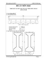
For the example of a square internal span of
a flat slab (Fig. 56) a rapid preliminary design
will be made possible for the design engineer
with the assistance of two diagrams, in which
guidance values for the slab thickness and
the size of the prestress are stated.
Figure 57: Recommended ratio of span to slab thickness as a function of service load to
self-weight (internal span of a flat slab)
Figure 56: Internal span of a fla slab
The design charts (Figs. 57 and 58) are
based upon the following conditions:
1. A factor of safety of y = 1.8 is to be
maintained under service load.
2. Under self-weight and initial prestress the
tensile stress 6c;t for a concrete for which
f2c8 = 30 N/mm2 shall not exceed 1.0
N/mm2.
3. The ultimate moment shall be capable of
being resisted by the specified minimum
ordinary reinforcement or, in the case of
large live loads, by increased ordinary
reinforcement, together with the
corresponding post-tensioning steel.
The post-tensioning steel (tendons in the
span and over the columns) and the ordinary
reinforcement are assumed as uniformly
distributed across the entire span. The
tendons are to be arranged according to
Chapter 5.1. and the ordinary reinforcement
according to Fig. 35.
From conditon 1, the necessary values are
obtained for the prestress and ordinary
reinforcement as a function of the slab
thickness and span. Conditon 2 limits the
Figure 58: Ratio of transverse component a from prestress to self-weight g as a function of
service
maximum admissible prestress. In flat slabs,
the lower face in the column region is usually
the determining feature. In special cases,
ordinary reinforcement can be placed there.
The concrete tensile stress oct (condition 2)
should then be limited to σ ct 2.0 N/mm 2 .
With condition 3, a guidance value is
obtained for economic slab thickness
(Fig.57). It is recommended that the ratio I/h
shall be chosen not greater than 40. In
buildings the slab thickness should normally
not be less than 160 mm.
Fig. 57 and 58 can be used correspondingly
for edge and corner spans.
Procedure in the preliminary design of a flat
slab:
Given: span I, column dimensions, live load
q
1. Estimation of the ratio I/h → self-weight g.
2. With ratio of service load (g+q) to
selfweight g and span I, determine slab
thickness h from Fig. 57; if necessary
correct g.
3. With I, h and (g+q)/g; determine
transverse component from Fig. 58 and
from this prestress; estimate approximate
quantity of ordinary reinforcement.
4. Check for punching; if necessary flare out
column head or choose higher concrete
quality or increase h.
The practical execution of a preliminary
design will be found in the calculation
example (Chapter 8.2.).
19
8. Execution of the calculations
8.1. Flow diagram
- Material properties:
Concrete
f28
= 35 N/mm2
c
2
fcd
= 0.6 . f28
c = 21 N/mm
Monostrands ∅ 15 mm (0.6")
Ap
= 146 mm2
fpy
= 1570 N/mm 2
fpu
= 1770 N/mm 2
Prestressing steel
5
Ep
= 1.95 ⋅ 10 N/mm2
very low relaxation (3%)
Admissible stresses:
- at stressing: 0.75 fpu
- after wedge draw-in: max. 0.70 fpu
Friction coefficients: µ=0.06
k = 0.0005/m
2
fsy = 460 N/mm
Reinforcing steel
- Concrete cover:
Prestressing steel
Reinforcing steel
cp
cs
=
=
30 mm
15 mm
- Long-term losses (incl. relaxation): assumed to be 10% (see Chapter 4.3.2.)
8.2.2. Preliminary design
Determination of slab thickness:
Assumption: I/h = 35
→h=
8.40
= 0.24 m
35
g = 0.24 ⋅ 25 = 6 kN/m 2
q=
5 kN/m2
11 kN/m2
g+q 11
=
= 1.83; hence from Fig. 57
g
6
→I/h = 36
h=
8.40
= 0.233 m
36
chosen: h=0.24 m
Determination of prestress:
a) Longitudinal direction:
g+q
0.24 ⋅ 1000
= 1.83;κ =
2
8.40 ⋅ 25
g
= 0.136;
hence from Fig. 58
→ u = 1.39; u = 1.39 . 6 = 8.34 kN/m2
g
2
P =u.I
8 . hp
2
hp = 0.144 . 4.20 = 0.178 m (Fig. 60)
2
3.78
8.2. Calculation example
P = 8.34 ⋅ 8.40
8 . 0.178
8.2.1. Bases
- Type of structure: commercial building
on 7.80 m width: P = 7.80 - 413 = 3221 kN
per strand: PL= 146 .1770 . 0.7 . 10 -3 = 181 kN
2
Number of strands:np= 3221 = 17.8
181
- Geometry: see Fig. 59
- Loadings:
Live load
Floor finishes
Walls
20
= 413 kN/m
→ 18 monostrands ∅ 15 mm on 7.80 m width
p =
gB =
gw =
q
=
kN/m2
2.5
1.OkN/m2
1.5 kN/m2
5.0 kN/m2
on 7.40 m width: np= 7.40 . 17.8= 16.9
7.80
→ 17 monostrands ∅ 15 mm on 7.40 m width
Figure 59: Plan showing dimensions
Figure 60: Tendon profile in longitudinal direction (internal span)
on 6.60 m width: np = 6.60 . 17.8 = 15.1
7.80
Figure 61: Tendon profile in transverse direction (internal span)
→18 monostrands 0 15 mm on 8.40 m width
on 7.20 m width: np =
→ 16 monostrands 0 15 mm on 6.60 m width
on 2.40 m width: np = 2.40 . 17.8 = 5.5
7.80
→ 6 monostrands ∅ 15 mm on 2.40 m width
b) Transverse direction:
.
g+q
=1.83;κ= 0.24 1000 = 0.158
2
g
7.80 . 25
hence from Fig. 58
→ u = 1.41;u=1.41. 6 = 8.46kN/m2
g
7.802
hp =0.135 .
2
= 0.167 m (Fig. 61)
3.51
P=
8.46 . 7.802
= 385 kN/m
8 . 0.167
on 8.40 m width: P=8.40 . 385=3234 kN
3234
=17.9
Number of strands: np=
181
7.20 .
17.9 =15.3
8,40
→16 monostrands 0 15 mm on 7.20 m width
- Determination of ordinary reinforcement:
a) Top reinforcement:
In the region of the punching cone:
ps=0.3% (Fig. 35)
Average of effective depth of reinforcement in both directions:
dsc = 240 - 15 - 15 = 210 mm (approx. value)
Width bcd (Fig. 30):
b = b +3d = 450 + 3 . 210 = 1080 mm
cd
c
sc
→ ASS = 0.003 . 210 . 1080 = 680 mm2
chosen: 7 ∅12 mm (Ass= 791 mm2)
In column strip:
ps= 0.15% (Fig. 35)
longitudinally:
bg = 0.4 . 7800 -1080 = 2040 mm
A =0.0015 .210 . 2040 = 643 mm2
sg
chosen: 6 ∅12 mm (Asg=678 mm2 )
21
Figure 62: Influence zone column 1
Figure 63: Tendon profile in critical shear periphery
transversely:
bg = 0.4 ⋅ 8400 -1080 = 2280 mm
Asg =0.0015 ⋅ 210 ⋅ 2280=718 mm2
chosen: 4+4 ∅ 12 mm (Asg= 904 mm2)
b) Bottom reinforcement:
• Internal spans: none
• Edge spans: ps ≥ 0.15 - 0.50 ⋅ pp (Formula 4.2.)
longitudinally:
pp= np ⋅ Ap = 18 ⋅ 146
dp ⋅ b
200 ⋅ 7800
= 0.17%
→ ps ≥ 0.15-0.50 ⋅ 0.17 = 0.065%
→ As ≥ 0.065 ⋅ 220 ⋅ 10 = 143 mm2/m
chosen:∅ 6 mm, spacing 175 mm
transversely:
pp ≥ = 18 ⋅ 146 = 0.16%
200 ⋅ 8400
→ps ≥ 0.07%
→As ≥ 0.07⋅ 220 ⋅ 10 = 154 mm2/m
chosen:∅ 6 mm, spacing 175 mm
Check for punching:
Determining column 1 (Fig. 62):
g+q = 11 kN/m2
Vg+q = 11. 7.60 . 8.60 = 719kN
Prestress:
50% within the critical shear periphery, i.e. 9 monostrands in each
direction
Point of inflection:
According to Fig. 30 the point of inflection ideally lies at a distance ds / 2
from the column edge. In Figs. 60 and 61 it is assumed that the
dimensions of the column are not yet known and the point of inflection
is adopted at a distance 0.051 from the column axis (value from
experience). In Fig. 62 the dimensions of the column have been
established. Thus the real position of the point of inflection is known.
The values given in Figs. 60 and 61 change accordingly (Fig. 63).
longitudinally :
tga= 2 ⋅ 13 = 0.078 = sina (Fig. 63a)
332
V =2.0.078.181.9.09=229kN
p
(Factor 0.9=10% long-term losses)
transversely :
tga= 2 ⋅ 12 = 0.072 = sina (Fig. 63b)
332
V =2 . 0.072 . 181. 9 . 0.9 = 211 kN
p
ΣV p=440 kN
22
Figure 64: Tendon profile in longitudinal direction (edge span)
Figure 65: influence of wedge draw-in
23