Phân tích dẻo kết cấu
Bạn đang xem bản rút gọn của tài liệu. Xem và tải ngay bản đầy đủ của tài liệu tại đây (101.25 KB, 14 trang )
Design of Steel Structures
Prof. S.R.Satish Kumar and Prof. A.R.Santha Kumar
2.5 Plastic analysis
In plastic analysis and design of a structure, the ultimate load of the
structure as a whole is regarded as the design criterion. The term plastic has
occurred due to the fact that the ultimate load is found from the strength of steel
in the plastic range. This method is rapid and provides a rational approach for the
analysis of the structure. It also provides striking economy as regards the weight
of steel since the sections required by this method are smaller in size than those
required by the method of elastic analysis. Plastic analysis and design has its
main application in the analysis and design of statically indeterminate framed
structures.
2.5.1 Basics of plastic analysis
Plastic analysis is based on the idealization of the stress-strain curve as
elastic-perfectly-plastic. It is further assumed that the width-thickness ratio of
plate elements is small so that local buckling does not occur- in other words the
sections will classify as plastic. With these assumptions, it can be said that the
section will reach its plastic moment capacity and then undergo considerable
rotation at this moment. With these assumptions, we will now look at the
behaviour of a beam up to collapse.
Consider a simply supported beam subjected to a point load W at midspan. as shown in Fig. 2.14(a). The elastic bending moment at the ends is w 2/12
and at mid-span is w 2/24, where
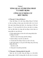
is the span. The stress distribution across any
cross section is linear [Fig. 2.15(a)]. As W is increased gradually, the bending
moment at every section increases and the stresses also increase. At a section
Indian Institute of Technology Madras
Design of Steel Structures
Prof. S.R.Satish Kumar and Prof. A.R.Santha Kumar
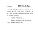
close to the support where the bending moment is maximum, the stresses in the
extreme fibers reach the yield stress. The moment corresponding to this state is
called the first yield moment My, of the cross section. But this does not imply
failure as the beam can continue to take additional load. As the load continues to
increase, more and more fibers reach the yield stress and the stress distribution
is as shown in Fig 2.15(b). Eventually the whole of the cross section reaches the
yield stress and the corresponding stress distribution is as shown in Fig. 2.15(c).
The moment corresponding to this state is known as the plastic moment of the
cross section and is denoted by Mp. In order to find out the fully plastic moment
of a yielded section of a beam, we employ the force equilibrium equation, namely
the total force in compression and the total force in tension over that section are
equal.
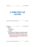
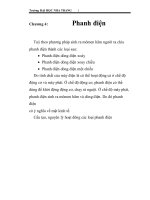
Collapse mechanism
w
Plastic hinges
Mp
Plastic hinges
Bending Moment Diagram
Mp
Mp
Fig. 2.14 Formation of a collapse mechanism in a fixed beam
(a) at My
(b) My < M
(c) at Mp
Fig. 2.15 Plastification of cross-section under
Indian Institute of Technology Madras
Design of Steel Structures
Prof. S.R.Satish Kumar and Prof. A.R.Santha Kumar
The ratio of the plastic moment to the yield moment is known as the
shape factor since it depends on the shape of the cross section. The cross
section is not capable of resisting any additional moment but may maintain this
moment for some amount of rotation in which case it acts like a plastic hinge. If
this is so, then for further loading, the beam, acts as if it is simply supported with
two additional moments Mp on either side, and continues to carry additional loads
until a third plastic hinge forms at mid-span when the bending moment at that
section reaches Mp. The beam is then said to have developed a collapse
mechanism and will collapse as shown in Fig 2.14(b). If the section is thinwalled, due to local buckling, it may not be able to sustain the moment for
additional rotations and may collapse either before or soon after attaining the
plastic moment. It may be noted that formation of a single plastic hinge gives a
collapse mechanism for a simply supported beam. The ratio of the ultimate
rotation to the yield rotation is called the rotation capacity of the section. The
yield and the plastic moments together with the rotation capacity of the crosssection are used to classify the sections.
Shape factor
As described previously there will be two stress blocks, one in tension, the other
in compression, both of which will be at yield stress. For equilibrium of the cross
section, the areas in compression and tension must be equal. For a rectangular
cross section, the elastic moment is given by,
M=
Indian Institute of Technology Madras
bd 2
fy
6
(2.21a)
Design of Steel Structures
Prof. S.R.Satish Kumar and Prof. A.R.Santha Kumar
The plastic moment is obtained from,
d d
M p = 2.b. . .f y
2 4
=
bd 2
fy
4
(2.21b)
Thus, for a rectangular section the plastic moment Mp is about 1.5 times
greater than the elastic moment capacity. For an I-section the value of shape
factor is about 1.12.
Theoretically, the plastic hinges are assumed to form at points at which
plastic rotations occur. Thus the length of a plastic hinge is considered as zero.
However, the values of moment, at the adjacent section of the yield zone are
more than the yield moment upto a certain length ∆L, of the structural member.
This length ∆L, is known as the hinged length. The hinged length depends upon
the type of loading and the geometry of the cross-section of the structural
member. The region of hinged length is known as region of yield or plasticity.
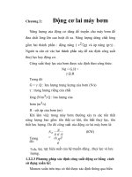
Rigid plastic analysis
W
h
L/2
L/2
b
x
MY
MY
Mp
Fig. 2.16
In a simply supported beam (Fig. 2.16) with central concentrated load, the
maximum bending moment occurs at the centre of the beam. As the load is
Indian Institute of Technology Madras
Design of Steel Structures
Prof. S.R.Satish Kumar and Prof. A.R.Santha Kumar
increased gradually, this moment reaches the fully plastic moment of the section
Mp and a plastic hinge is formed at the centre.
Let x (= ∆L) be the length of plasticity zone.
From the bending moment diagram shown in Fig. 2.16
(L-x)Mp=LMy
x=L/3
(2.22)
Therefore the hinged length of the plasticity zone is equal to one-third of
the span in this case.
Mp =
Wl
4
= fy .
bh 2
4
bh 2
My = fy .
6
My =
⎛
bh 2 ⎞
=
Z
∵
⎜⎜ p
⎟
4 ⎟⎠
⎝
⎛
bh 2
= ⎜ fy .
⎜
4
⎝
⎞2
⎟⎟
⎠3
2
Mp
3
2.5.2 Principles of plastic analysis
Fundamental conditions for plastic analysis
(i)
Mechanism condition: The ultimate or collapse load is reached when a
mechanism is formed. The number of plastic hinges developed should be
just sufficient to form a mechanism.
(ii)
Equilibrium condition : ∑Fx = 0, ∑Fy = 0, ∑Mxy = 0
(iii)
Plastic moment condition: The bending moment at any section of the
structure should not be more than the fully plastic moment of the section.
Indian Institute of Technology Madras
Design of Steel Structures
Prof. S.R.Satish Kumar and Prof. A.R.Santha Kumar
Collapse mechanisms
When a system of loads is applied to an elastic body, it will deform and will
show a resistance against deformation. Such a body is known as a structure. On
the other hand if no resistance is set up against deformation in the body, then it is
known as a mechanism.
Various types of independent mechanisms are identified to enable
prediction of possible failure modes of a structure.
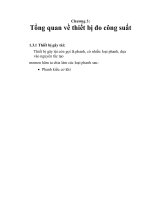
(i) Beam mechanism
Fig. 2.17 shows a simply supported and a fixed beam and the
corresponding mechanisms.
Fig. 2.17
(ii) Panel or Sway mechanism
Fig. 2.18 (A) shows a panel or sway mechanism for a portal frame fixed at
both ends.
(A) Panel mechanism
(B) Gable mechanism
Fig. 2.18
Indian Institute of Technology Madras
(C) Joint mechanism
Design of Steel Structures
Prof. S.R.Satish Kumar and Prof. A.R.Santha Kumar
(iii) Gable mechanism
Fig. 2.18(B) shows the gable mechanism for a gable structure fixed at
both the supports.
(iv) Joint mechanism
Fig. 2.18(C) shows a joint mechanism. It occurs at a joint where more than
two structural members meet.
Combined mechanism
Various combinations of independent mechanisms can be made
depending upon whether the frame is made of strong beam and weak column
combination or strong column and weak beam combination. The one shown in
Fig. 2.19 is a combination of a beam and sway mechanism. Failure is triggered
by formation of hinges at the bases of the columns and the weak beam
developing two hinges. This is illustrated by the right hinge being shown on the
beam, in a position slightly away from the joint.
Two hinges developed on
the beam
Fig. 2.19 Combined mechanism
From the above examples, it is seen that the number of hinges needed to
form a mechanism equals the statical redundancy of the structure plus one.
Indian Institute of Technology Madras
Design of Steel Structures
Prof. S.R.Satish Kumar and Prof. A.R.Santha Kumar
Plastic load factor and theorems of plastic collapse
The plastic load factor at rigid plastic collapse (λp) is defined as the lowest
multiple of the design loads which will cause the whole structure, or any part of it
to become a mechanism.
In a limit state approach, the designer is seeking to ensure that at the
appropriate factored loads the structure will not fail. Thus the rigid plastic load
factor λp must not be less than unity.
The number of independent mechanisms (n) is related to the number of
possible plastic hinge locations (h) and the number of degree of redundancy (r)
of the frame by the equation.
n=h–r
(2.23)
The three theorems of plastic collapse are given below.
Lower bound or Static theorem
A load factor (λs ) computed on the basis of an arbitrarily assumed
bending moment diagram which is in equilibrium with the applied loads and
where the fully plastic moment of resistance is nowhere exceeded will always be
less than or at best equal to the load factor at rigid plastic collapse, (λp). In other
words, λp is the highest value of λs which can be found.
Upper bound or Kinematic theorem
A load factor (λk) computed on the basis of an arbitrarily assumed
mechanism will always be greater than, or at best equal to the load factor at rigid
Indian Institute of Technology Madras
Design of Steel Structures
Prof. S.R.Satish Kumar and Prof. A.R.Santha Kumar
plastic collapse (λp ). In other words, λp is the lowest value of λk which can be
found.
Uniqueness theorem
If both the above criteria are satisfied, then the resulting load factor
corresponds to its value at rigid plastic collapse (λp).
Mechanism method
In the mechanism or kinematics method of plastic analysis, various plastic
failure mechanisms are evaluated. The plastic collapse loads corresponding to
various failure mechanisms are obtained by equating the internal work at the
plastic hinges to the external work by loads during the virtual displacement. This
requires evaluation of displacements and plastic hinge rotations.
As the plastic deformations at collapse are considerably larger than elastic
ones, it is assumed that the frame remains rigid between supports and hinge
positions i.e. all plastic rotation occurs at the plastic hinges.
Considering a simply supported beam subjected to a point load at
midspan, the maximum strain will take place at the centre of the span where a
plastic hinge will be formed at yield of full section. The remainder of the beam
will remain straight, thus the entire energy will be absorbed by the rotation of the
plastic hinge.
Considering a centrally loaded simply supported beam at the instant of
plastic collapse (see Fig. 2.17)
Indian Institute of Technology Madras
Design of Steel Structures
Prof. S.R.Satish Kumar and Prof. A.R.Santha Kumar
Workdone at the plastic hinge = Mp 2θ
(2.24a)
⎛L ⎞
Workdone by the displacement of the load = W ⎜ . θ ⎟
⎝2 ⎠
(2.24b)
At collapse, these two must be equal
⎛L ⎞
W ⎜ .θ ⎟
⎝2 ⎠
2Mp.θ =
Mp =
WL
4
(2.25)
The moment at collapse of an encastre beam with a uniform load is
similarly worked out from Fig. 2.20. It should be noted that three hinges are
required to be formed at A, B and C just before collapse.
Workdone at the three plastic hinges =Mp (θ + 2θ +θ ) = 4Mpθ
Workdone by the displacement of the load =W/L . L/2 . L/2 . θ
(2.26.a)
(2.26.b)
W / unit length
P=0
P=0
MA
A
B
C
Loading
MB
L
MP
θ
θ
MP
MP
MP
Collapse
2θ
Fig. 2.20 Encastre beam
WL
θ = 4M p θ
4
WL =16 M p
Indian Institute of Technology Madras
(2.27)
Design of Steel Structures
Prof. S.R.Satish Kumar and Prof. A.R.Santha Kumar
WL
16
Mp =
(2.28)
In other words the load causing plastic collapse of a section of known
value of Mp is given by eqn. (2.28).
Rectangular portal framework and interaction diagrams
The same principle is applicable to frames as indicated in Fig. 2.21(a)
where a portal frame with constant plastic moment of resistance Mp throughout is
subjected to two independent loads H and V.
V
V
H
H
a
H
a
θ
a
θ
θ
θ
(a)
V
θ
θ
2θ
V
H
2θ
θ
θ
(b
(c)
θ
θ
(d)
Fig.2.21 Possible failure mechanisms
This frame may distort in more than one mode.
There are basic
independent modes for the portal frame, the pure sway of Fig. 2.21 (b) and a
beam collapse as indicated in Fig. 2.21 (c). There is now however the possibility
of the modes combining as shown in Fig. 2.21(d).
From Fig. 2.21(b)
Va / Mp
6
A
4
B
C
2
D
0
2
4
Fig. 2.22
Indian Institute of Technology Madras
6
Ha
p p
H a/ M
/M
Design of Steel Structures
Prof. S.R.Satish Kumar and Prof. A.R.Santha Kumar
Work done in hinges = 4 Mpθ
Work done by loads = Haθ
At incipient collapse Ha /Mp= 4
(2.29)
From Fig. 2.21 (c)
Work done in hinges = 4 Mpθ
Work done by loads = Vaθ
At incipient collapse = Va / Mp = 4
(2.30)
From Fig. 2.21(d)
Work done in hinges = 6 Mpθ
Work done by loads = Haθ + Vaθ
At incipient collapse Ha / Mp + Va / Mp = 6
(2.31)
The resulting equations, which represent the collapse criteria, are plotted
on the interaction diagram of Fig. 2.22. Since any line radiating from the origin
represents proportional loading, the first mechanism line intersected represents
failure. The failure condition is therefore the line ABCD and any load condition
within the area OABCD is therefore safe.
Stability
For plastically designed frames three stability criteria have to be considered
for ensuring the safety of the frame. These are
Indian Institute of Technology Madras
Design of Steel Structures
Prof. S.R.Satish Kumar and Prof. A.R.Santha Kumar
1. General Frame Stability.
2. Local Buckling Criterion.
3. Restraints.
Effect of axial load and shear
If a member is subjected to the combined action of bending moment and
axial force, the plastic moment capacity will be reduced.
The presence of an axial load implies that the sum of the tension and
compression forces in the section is not zero (Fig. 2.23). This means that the
neutral axis moves away from the equal area axis providing an additional area in
tension or compression depending on the type of axial load.
the interaction equation can be obtained:
Mx/Mp = 1 – P2/ Py
(2.32)
The presence of shear forces will also reduce the moment capacity.
b
fy
fy
C
d/2
C
d
C
y1
T
fy
Total stresses
fy
T
fy
=
Bending
+
Axial
compression
Fig. 2.23 Effect of axial force on plastic moment capacity
Indian Institute of Technology Madras
Design of Steel Structures
Prof. S.R.Satish Kumar and Prof. A.R.Santha Kumar
Plastic analysis for more than one condition of loading
When more than one condition of loading can be applied to a beam or
structure, it may not always be obvious which is critical. It is necessary then to
perform separate calculations, one for each loading condition, the section being
determined by the solution requiring the largest plastic moment.
Unlike the elastic method of design in which moments produced by
different loading systems can be added together, plastic moments obtained by
different loading systems cannot be combined, i.e. the plastic moment calculated
for a given set of loads is only valid for that loading condition. This is because the
'Principle of Superposition' becomes invalid when parts of the structure have
yielded.
Indian Institute of Technology Madras