Giao trinh bai tap ece 110 hw5
Bạn đang xem bản rút gọn của tài liệu. Xem và tải ngay bản đầy đủ của tài liệu tại đây (110.35 KB, 10 trang )
ECE430
Power Circuits and Electromechanics
Dr. Nam Nguyen-Quang
Fall 2009
/>
Lecture 3
1
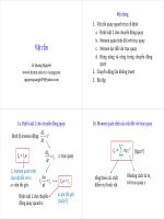
Introduction
Electromagnetic theory: basis for explaining the operation of all
electrical and electromechanical systems.
There are magnetic field and electric field systems, the discussion is
restricted to magnetic field systems.
Integral form of Maxwell’s equations
C
C
H dl
J
S
E dl
J n da 0
B n da 0
f
S
S
S
n da
Ampere’s law
B
n da
t
Faraday’s law
f
Conservation of charge
Gauss’s law
Lecture 3
2
1
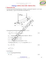
Static magnetic circuits
There are no moving components in static magnetic circuits.
Toroid: N uniformly wound turns. r0 and r1 are inner and outer radii.
Consider the contour corresponding to the mean radius r = (r0 + r1) / 2,
assuming magnetic field intensity Hc is uniform inside the core. Using
Ampere’s circuital law, it can be determined that Hc(2r) = Ni. Or,
H c l c Ni
where lc = 2r is the mean length in core. Assuming
B is a linear function of H in the core, the flux
density in the core is
Bc H c
Ni
Wb /m 2
lc
Lecture 3
3
Static magnetic circuits (cont.)
Flux is given by
c Bc Ac
Ni
Ni
Ac
Wb
lc
l c Ac
where is the magnetic permeability of the core material, Ac is the core
cross-sectional area.
Define Ni as magneto motive force (mmf), reluctance can be defined as
l
Ni mmf
c R (At/Wb)
c
flux Ac
P = 1/R is called permeance. Flux linkage is now defined as = Nc =
PN2i. By definition, self inductance L of a coil is given by L
Lecture 3
N2
PN 2
i
R
4
2
Static magnetic circuits (cont.)
There are similarities between electrical and magnetic circuits
mmf
flux
reluctance
permeance
voltage
current
resistance
conductance
Toroid with air gap (no fringing): There is magnetic field intensity H in
both the air gap and the iron portion. lg – length of the air gap, lc – mean
length of the iron portion. Applying ACL around the contour c
Ni H g l g H clc
Bg
0
lg
Bc
lc
r 0
where 0 = 4 x 10⁷ H/m is the air’s permeability, and r is the relative
permeability of the core material.
Lecture 3
5
Static magnetic circuits (cont.)
Applying Gauss’s law on the closed surface s covering one magnetic
pole, BgAg = BcAc. For the case of no fringing, Ag = Ac. Hence, Bg = Bc.
Divide the mmf by the flux to calculate equivalent reluctance
lg
l
Ni
c R g Rc
0 Ag Ac
Where Rg and Rc are reluctances of the air gap and the core,
respectively. In the equivalent magnetic circuit, these are in series.
Suppose there is “fringing”, i.e., not all the flux is confined to the area
between the two faces of iron portion. In this case, Ag > Ac, i.e., effective
air gap area increases. This can be accounted for empirically,
Ac ab, Ag a l g b l g
Lecture 3
6
3
Class examples
Ex. 3.1: Find the required mmf to produce a given flux density. Air
gap and core length and area are known.
0.06
47.7 103 At/Wb
7
4
10 4 10 10
0.001
Rg
7.23 106 At/Wb
7
4
4 10 1.1 10
Rc
4
Bg Ag 0.51.1 10
4
5.5 10
4
Wb
Hence,
Ni R c R g 47.7 7230 10 3 5.5 10 5 400 At
Lecture 3
7
Class examples (cont.)
Ex. 3.2: Find the flux through the coils. All air gaps are the same in
length and area. Iron’s permeability is infinite and ignore fringing.
0.1 10
4 10 4 10 1.989 10
2
R1 R 2 R 3 R
7
4
6
At/Wb
2500
In the equivalent circuit, positive directions
for 1, 2, and 3 are shown. The algebraic
sum of the fluxes at node a must be zero.
Let mmf of node a wrt. b be F, then
500
b
1
R
a
2
1500
2500 F 500 F F 1500
0
R
R
R
Hence,
R
R
3
F 500, 1 10 3 Wb, 2 0, 3 10 3 Wb
Lecture 3
8
4
In class quiz
Problem 1: A toroid has a mean length with a radius of 500 mm, the
working flux density in the air gap is 0.6 Wb/m2, creating by a coil of 100
turns. An air gap with the length of 2 mm is made. Given a = 20 mm.
Ignore the reluctance of the core.
a) Find the required excitation current
b) Determine the self inductance of the coil
Special question: Suppose you were asked to build a linear variable
inductor. Describe your solution, considering fringing effect and
reluctance of the core (if exists)?
Lecture 3
9
Mutual inductance
Mutual inductance: parameter related induced voltage in one coil with
time varying current in another coil.
Consider two coils wound on the same magnetic core, coil 1 is
excited whilst coil 1 is open. The total flux linking coil 1 is
11 l1 21
where l1 (called leakage flux) links to coil 1 only; whereas, 21 is the
mutual flux linking to both the coils, also the flux linking coil 2 due to
current in coil 1. The order of subscripts is important.
Since coil 2 is open circuited, the flux linkage of this coil is
2 N 221
Lecture 3
10
5
Mutual inductance (cont.)
21 is linearly proportional to the current i1, hence
2 N 221 M 21i1
The induced voltage v2 (due to the change of flux linkage) is given by
v2
d 2
di
M 21 1
dt
dt
M21 is called the mutual inductance between the coils. Similarly,
induced voltage v1 in coil 1 can also be determined as follows.
11 is proportional to i1, hence 1 N111 L1i1 , then
v1
d1
di
L1 1
dt
dt
with L1 is the self inductance of coil 1, as you may know.
Lecture 3
11
Mutual inductance (cont.)
Consider now the case where coil 1 is open and coil 2 is excited. The
same procedure can be used to calculate induced voltages.
22 l 2 12
1 N112 M 12 i2
v2
2 N 222 L2i2
v1
d1
di
M 12 2
dt
dt
d2
di
L2 2
dt
dt
where L2 is the self inductance of coil 2, as you may know.
From energy considerations, it can be shown that M21 = M12 = M.
Finally, consider now the case where both the coils are excited.
1 l1 21 12 11 12
2 21 l 2 12 21 22
Lecture 3
12
6
Mutual inductance (cont.)
Noting that M21 = M12 = M
1 N111 N112 L1i1 Mi2
2 N 2 21 N 2 22 Mi1 L2 i2
By differentiating those, induced voltages can be calculated
v1 L1
di1
di
M 2
dt
dt
v2 M
di1
di
L2 2
dt
dt
Coefficient of coupling between the two coils is defined by k
It can be shown that 0 k 1, or equivalently, 0 M
M
L1 L2
L1 L2
Most air core transformers are loosely coupled (k < 0.5), whilst iron
core transformers are tightly coupled (k > 0.5, can approach 1).
Lecture 3
13
Example
Ex. 3.4: Given reluctances of three air gaps in the magnetic circuit.
Draw equivalent circuit and compute flux linkages and inductances.
N 1i1 R3 1 2 R11
N 2 i 2 R 2 2 R 3 1 2
100i1 51 2 2 10
100i 2 21 4 2 10
6
1
6
Solving these equations for 1 and 2
N1i1
R1
R3
6
1 25i1 12.5i 2 10 6 2 12.5i1 31.25i2 10
From
R2
1 N11 25i1 12.5i2 10 4
2 N 22 12.5i1 31.25i2 10 4
It can be seen that
L1 25 10
4
L2 31.25 10 4 H 3.125 mH
N2i2
2
H 2.5 mH
M 12.5 10 4 H 1.25 mH
Lecture 3
14
7
Polarity markings (dot convention)
Lenz’s law: the voltage induced is in such a direction that the current
due to it opposes the flux causing the voltage.
Signs of mutually induced voltages are monitored by a dot marking
convention. A current i entering a dotted (undotted) terminal in one
winding induces a voltage Mdi/dt with positive polarity at the dotted
(undotted) terminal of the other winding.
Two problems: (1) given the coil configuration, determine the dot
markings. (2) given the dot markings, how they are used in writing
equations.
Lecture 3
15
Determining polarity markings
Steps:
Arbitrarily select one terminal of a coil and assign a dot in one coil.
Assume a current flowing into the selected dotted terminal and
determine the flux flowing in the core.
Select an arbitrary terminal of the second coil and assign a positive
test current to it.
Determine flux direction due to this current.
Compare directions of two fluxes. If both is additive, then a dot is
placed in the second coil where the test current enters.
If the fluxes are in opposite directions, then a dot is placed in the
second coil at the terminal where the current leaves.
Lecture 3
16
8
Practical ways of determining dot markings
For a device such as a transformer, there is no way of knowing how
the coils are wound, therefore a practical way is adopted:
A DC source is used to excite one
coil of the transformer.
+
Place the dot on the terminal to
_
which the + side of DC source is
connected.
Close the switch: up-scale kick in voltmeter => the dot on the other coil is
on the + side of the voltmeter. Down-scale momentary deflection in
voltmeter => the dot is placed the – side of the voltmeter.
Lecture 3
17
Writing equations with mutually coupled coils
Given 2 mutually coupled coils and dot markings, write loop equations.
Choose arbitrary direction for currents.
Rule: Reference current enters a dotted (undotted) terminal, induced
voltage in the other coil is positive at the dotted (undotted) terminal.
Reference current leaves a dotted (undotted) terminal, induced voltage at
the dotted (undotted) terminal of the other coil is negative.
di1
di
M 2
dt
dt
di
di
v 2 i 2 R 2 L2 2 M 1
dt
dt
v1 i1 R1 L1
Lecture 3
R1
i1
v1
R2
M
i2
v2
18
9
Example
Ex 3.6: Write loop equations for a circuit with mutually coupled coils.
Assuming zero initial voltage on capacitor
L1
0
R1
i1
v1 i1 R1 i1 i2 R2
L2
R2
v1
d
i1 i2 M di2
dt
dt
(i1 – i2)
C
M
i2
L1
di
1 t
d
d
i2 dt L2 2 M i1 i 2 L1 i2 i1
C 0
dt
dt
dt
di
M 2 i2 i1 R2
dt
Lecture 3
19
Lecture 3
20
In-class quiz
Problem 3.15.
10