Tai lieu dieu khien tro luc nang
Bạn đang xem bản rút gọn của tài liệu. Xem và tải ngay bản đầy đủ của tài liệu tại đây (680.01 KB, 7 trang )
Proceedings of the RAAD 2012
21th International Workshop on Robotics in Alpe-Adria-Danube Region
September 10-13, 2012, Napoli, Italy
Control of a Power Assisted Lifting Device
Dimeas Fotiosa , Koustoumpardis Panagiotisb and Aspragathos Nikosc
Department of Mechanical Engineering & Aeronautics, University of Patras –
Patra, Greece
E-mail: a , b
c
Abstract. In this paper, two control schemes for a power assisted lifting device are presented.
Such a device can be used to hoist a heavy object in cooperation with a human by reducing
the operator’s burden. The proposed system includes an admittance controller that establishes
the desired dynamic relationship between the applied force to the object and the motion, while
an inner control loop regulates the velocity of the object. For the adaptation to a variety of
loads, an online adaption controller is implemented based on a neural network with
backpropagation training. Alternatively, a gain scheduling PID controller is designed for the
inner loop. This controller measures the object weight and tunes the gains with predefined
rules. The performance of these two adaptation methods is demonstrated on an experimental
setup and the results are illustrated and discussed at the end of this manuscript.
Keywords. Power Assist, Admittance Control, Neural Network Control, PID Gain
Scheduling
powered crane using a PD controller (Doi et al.,
2008). Osamura implemented a power assist system
with an ideal plant model and a PD controller on a
horizontal slide door to provide comfortable
operational feeling (Osamura et al., 2007).
For force control problems, neural networks have
been widely used (Lin & Tzeng, 1999). Alternatively,
the neural network technique has been combined with
impedance control as an addition in order to improve
the controller robustness (Jung & Hsia, 1998).
The majority of the systems mentioned above,
calculate the assisting force according to the applied
force by the user. The force is either received from
the manipulation of the force sensor, which is a pretty
straightforward technique with many advantages, or
indirectly from the manipulation of the object itself.
The latter incorporates a loadcell within the
suspension system that withdraws the need of a
handle and facilitates the intuitive handling of an
object by the operator.
In this paper, a single degree-of-freedom power
assist system is developed that can be used for
moving objects in the vertical direction. Admittance
control is implemented to establish a relationship
between the imposed forces and the motion of the
object. To ensure that our object reaches the desired
velocity that derived from the admittance controller,
a neural network controller with online training is
designed that adapts to the variable plant parameters,
1. Introduction
A power assist system can be used to facilitate the
manipulation of a heavy object by a human operator
with a considerable reduction of the required force.
This system has a wide range of applications in
industry and healthcare e.g. in the manipulation of
heavy parts in assembly lines, in rehabilitation
through physiotherapy etc.
The last five decades many researchers have
worked on power assist systems. Lee (Lee et al.,
1999) developed a power assisted mobile robot arm,
based on impedance control (Hogan, 1985), that
follows the operator’s motion and attenuates the load
force. The same control method was also used on a
mobile robot arm to assist a human operator to carry
a long object (Hayashibara et al., 1999). Later, a
hybrid control framework was proposed that unifies
impedance and admittance control (Ott et al., 2010).
According to Ott, the mapping of force inputs to
motion outputs provides very good performance
when the environment is soft but results in poor
accuracy when the environment is stiff.
Further research on power assist systems was
made on a bridge crane (Miyoshi & Terashima, 2004)
that controls the velocity of the object in the vertical
direction in proportion to the applied force based on
and
robust control. Doi installed a power
assist system in the vertical direction of a pneumatic
1
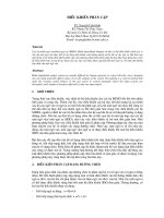
object is considered known and is compensated 1 by
the static friction T that appears in the drive system.
The walls of the guide that are illustrated in Fig. 2 are
not parts of the actual plant but were designed in
order to model the static friction in the drive system.
The motion of the mass can be expressed by the
following equation:
unlike most of the systems mentioned above, which
perform under certain parameters or boundaries. A
gain scheduling PID was also implemented for the
velocity control instead of the neural network
controller. A set of objects with different weights
were used on an experimental setup to investigate the
performance of the designed controllers in
hoisting/lowering and adaptation.
-
2. System Description
(1)
Later it will be demonstrated that the effects of
friction forces can be neglected. The known
component of gravitational force mg can be
numerically removed from the measured force and
the Fext can be given by the equation:
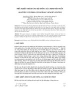
The proposed system (see Fig. 1) consists of an
electric motor that is mechanically coupled with a
drum. Rotation of the motor shaft causes a wire rope
to wrap around the drum and move the object that is
attached to the edge along the vertical direction.
The position of the object is calculated from a
rotary encoder installed at the drum shaft. Using a
numeric differentiation, the velocity of the object
is calculated. For the force measurement we selected
to mount a loadcell between the rope and the
suspended object and let the operator manipulate the
object itself rather than use a handle. As a result, the
operator would manipulate the object in a more
physical manner. The measured force consists of
three main components; the weight of the
object
, the human force
and the inertial
forces
. We assume that the wire rope is always
tensed and that its spring constant is very high. The
mass of the loadcell is very small and it has no
significant effect on the system dynamic response.
-
(2)
In order to obtain an accurate measurement of the
human force , the term
should be as small as
possible (
), otherwise it could affect the
dynamic response.
T
F
m
Fext
mg
Fig. 2. Single degree-of-freedom model
3.1. Admittance Control
To achieve power assisting movement, a desired
relationship between the input force and the output
velocity should be established. Both impedance and
admittance control have the ability to establish such a
relationship. In common implementations of
impedance control the external force
is measured
and F is commanded such that the following equation
of the motion is enforced:
(3)
This is a typical linear second-order relationship
where
is the deviation from a
reference trajectory
. The parameters
,
and
represent the desired inertia, damping and
stiffness respectively. In our system we do not want
to include a restoring force so we set
in order
to ensure that the actuator force F will be zero when
the user does not apply
. By setting
and
in (3), we get:
Fig. 1. Layout of control system
3. Design of the Controller
For the controller design let’s assume a simplified
single degree of freedom system in which a mass
interacts with the environment (see Fig. 2). The mass
of the object and displacement are m and x,
respectively, and the actuator force and external
measured force are F and Fext. The weight
of the
1
This assumption is valid only when
. A large static friction
T can be achieved with a high transmission ratio. In different case
when
, a breaking system is required.
2
unmodeled parameters are treated as disturbances and
are diminished.
The mass m of the object is a parameter that has
great impact in the plant dynamics and cannot be
considered as a disturbance. Since we want our
system to perform under a variety of loads an
adaptive controller must be designed.
(4)
where
.
By comparing Eq. (1) with the desired behaviour in
Eq. (4), we can derive the impedance control law
which gives the force applied by the actuator F. This
method will not be used, since it requires a very good
estimation of the plant parameters. In our system, it is
quite time consuming to calculate the dynamics
because these are changing, by lifting a variety of
objects.
As an alternative, admittance control is
considered. In contrast with the impedance control,
admittance control accepts force inputs and yields
motion outputs and implements an automatic control
system that imposes the actuating force F indirectly
to the plant. This procedure fits better to power assist
systems. Admittance control also provides high level
of accuracy in non-contact tasks.
Fh
Vr=0
Vd
Admittance
Neural Network Controller. Since the system
dynamics depend on the object weight, a
Feedforward Neural Network (FNN) velocity
controller is implemented, as shown in Fig. 4. The
FNN is composed of three layers with the
configuration (2-6-1), i.e. two linear neurons (L) in
the input layer, six in the hidden and one in the
output respectively (see Fig. 5). A sigmoid function
(S), which is bounded in magnitude between -1 and
1, is used for the neurons in the hidden and output
layers.
The
well-known
backpropagation
(Wasserman, 1989) training algorithm is used for the
online adaptation of the network’s weights and
thresholds b, which are set randomly in the
beginning.
The velocity error
(
is used in the
backpropagation part and is also fed back to the input
of the FNN together with the previous one [kT-T] in
order to close the controller’s loop.
+
-
Velocity
Control
u
F
Motor
Plant
Fext
V
Fig. 3. Block diagram of control system
Fh
Vr=0
In the block diagram of Fig. 3, the control system is
illustrated. It consists of the main control loop for the
admittance control and an inner loop for the velocity
controller. The main control loop is described by Eq.
(4). The reference velocity
is set to zero as a
necessary condition for the object to remain still
when no Fext is applied. When
, then
and the admittance control law can be rewritten as
follows:
Vd
Admittance
Fext
F
Motor
Plant
V
-
Fig. 4. Block diagram with neural network velocity control
b
S
(5)
S
Ve[kT]
L
S
The transformation of Eq. (5) in the discrete time
domain using a sampling period Ts and expressed in
terms of Vd, describes the admittance control law that
is used for the experimental implementation:
-
+
u
FNN
b
S
Ve[kT-T]
L
S
Input
Layer
S
u
Output
Layer
S
(6)
Hidden
Layer
Fig. 5. Neural network configuration
3.2. Velocity Controller
In series with the admittance controller a velocity
controller is placed, as shown is Fig. 3. The velocity
controller inputs the error
between the desired
velocity
that derived from the admittance
controller and the measured velocity V from a
feedback loop and outputs a voltage u to drive the
motor. As a result, the actuating force F is derived
indirectly from the velocity controller and any
PID Gain Scheduling. The second velocity
controller is a gain scheduling PID (see Fig. 6). The
gains of the controller are calculated for a pair of
different weights (1kg & 3kg) according to the
Ziegler-Nichols method with “no overshoot” rules.
More sample weights could be used or greater
deviation between them if our experimental setup had
3
bigger payload. This method includes offline
adaptation by computing the gains with linear
interpolation at the beginning of the process during
the initialization.
Gain Scheduling
Initial PID gains
Vr=0
Vd Ve
Admittance
+
Fh
Motor
The mass
indicates the desired mass for our
power assisted system. This value refers to the
desired behaviour of the system and should be
accomplished regardless of the actual object weight.
The parameter
represents the viscous damping in
which the desired mass moves and indicates the
sensitivity of our system to external forces.
Assuming
, a small external stimulation would
cause the object to move indefinitely because no
frictional forces are modelled. The actual frictional
forces on the plant would be perceived as disturbance
and would be compensated by the velocity control
system. A desired damping factor of 15Ns/m
indicates that in order to move an object with speed
0.06m/s (rated speed), the required force is:
Fext
F
u
PID
signal to compensate the gravity. In addition, the
appropriate gains are calculated in the gain
scheduling PID controller.
To implement the admittance controller the
following parameters are used:
Plant
V
-
Fig. 6. Block diagram with gain scheduled PID velocity
control
4. Experimental Evaluation
4.1. Setup
Our experimental setup (see Fig. 7) consists of a DC
motor with high ratio gearbox for non-backdrivability
along with a self-made hoist. The maximum
lifting/lowering velocity is 0.06m/s and the capacity
is 6kg. The rotational speed of the motor is controlled
with pulse width modulation (PWM) method through
a motor driver and is expressed as a percentage of the
rated rotational speed. The mass of the loadcell is
equal to 0.15kg and does not influence the dynamic
response of the system.
Both the motor and the sensors are connected to a
personal computer with Phidget interfaces. The
computer is a common laptop with 2.1GHz CPU
clock that acts as a controller. The communication
between the computer and the external interfaces is
performed via universal serial bus (USB) with
sampling period Ts=8ms.
To verify this assumption three different objects
weighting 1kg, 2kg and 3kg are selected and a
constant force equal to 0.9N is applied to them in
both directions, by adding and removing a mass equal
to 0.09kg. Then, the velocity of the object in each
experiment is plotted and the results are used to
investigate the performance between the two
controllers in the transient and the steady states. It is
expected that the object should move with a speed
equal to 0.06m/s.
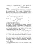
4.2. PID Gain Scheduling
To begin with, the PID is implemented in digital
form along with the admittance controller (Eq. (6)).
The gains of the controller are calculated in the
system initialization. For the integral term an antiwindup tracking is added to avoid instability due to
the saturation of the output velocity.
For three different masses a constant force equal
to 0.9N is applied for approximately two seconds in
each direction causing the lowering (negative values
of velocity) and the hoisting (positive values of
velocity) of the object respectively (see Fig. 8). The
experiments are conducted under a constant force
because we want to investigate the performance of
the controllers under the same conditions. The gains
for the mass of 2kg resulted from interpolation, while
the other two objects coincide with the gain values
obtained by the Ziegler-Nichols tuning. The criteria
for the evaluation of the control methods are the
quality of the response rate, the response smoothness
and the overshooting.
In Fig. 9, a summarized graphical representation
of the experiments is presented. The system response
is very fast in both directions, specifically in the
acceleration of the load. During deceleration (when
motor
winch
encoder
wire rope
loadcell
load
Fig. 7. Experimental setup
In order to switch to power assisted motion, an
initialization process must take place at the
beginning. The object weight is measured at
equilibrium point and is removed from the input
4
the external force is removed) a small delay appears
which becomes more evident with the increase of the
load. Another notable remark is that the velocity in
both directions differs from the rated one and
between the different weights mainly because of the
existence of the gravitational component as an
external torque to the motor. The ripples are
attributed to residual vibrations due to the flexibility
of the system structure.
uniformity of the velocity among the different
weights and especially during the transient state. The
responses at the acceleration and deceleration of the
object are very similar and meet the desired
specifications. During the steady state, the deviation
of the average velocity from the expected one
appears for the same reason as in the PID scheduling,
due to the gravitational component. The ripples are
considerably less and occur only during the steady
state.
4.4. PID vs. Neural Network
Before we come to a conclusion a comparison
between the two velocity controllers should be made.
Therefore, for each load of the experiments
demonstrated in Fig. 9 and 10, the velocity graphs of
the gain scheduled PID and the neural network are
overlaid in three figures.
Starting from the object with mass m=1kg, we
can see in Fig. 11 that both controllers accelerate in
steady state at the same time. The PID controller
causes much less ripple than the neural network and
more steady velocity, but it needs longer time for the
object to stop after the lifting.
In Fig. 12, comparative results for the object of
m=2kg are demonstrated. In this case we can also
derive valuable information for the performance of
the PID with gains that resulted from interpolation.
Both controllers respond very fast, while the PID
causes small leaps of the velocity during
deceleration. Unlike the previous graph, appeared in
Fig. 11, here the PID controller also causes more
ripples than the neural network.
For the heaviest object of our experiment with
m=3kg we can clearly see (Fig. 13) that the neural
network outperforms the PID gain scheduling. The
latter causes even bigger leaps during deceleration
and more intense ripples, while the neural network
responses very fast and with very little oscillation of
the velocity.
Summarizing the results, the scheduling PID
controller even though it performs better in small
loads, it causes undesirable effects in greater loads.
On the other hand, the performance of the neural
network controller is not affected by the increase of
the load and has better adaptability in rejecting
disturbances. It can be concluded that the neural
network as a velocity controller has better
generalization than the PID gain scheduling and
should be preferred in power assist systems where
heavy objects are carried.
Fig. 8. External force profile that was used in the
experiments
Fig. 9. Velocity of object for lowering and lifting with gain
scheduling PID control
Fig. 10. Velocity of object for lowering and lifting with
neural network control
4.3. Neural Network Controller
Substituting the PID controller with the neural
network, the same series of experiments are
conducted. In this case, the weights and thresholds of
the neural network are adapted online.
As it is illustrated in Fig. 10, the neural network
as a velocity controller demonstrates better
5
speed. We want to study the actual force that is
applied by the operator and the corresponding
velocity response in order to investigate the
performance of proposed synthesis of the admittance
and the velocity controllers.
In Fig. 14, the external force with the PID gain
scheduling controller is presented. The force that is
applied at the beginning of the movement tends to be
more than 0.9N mainly because the operator takes
into account the dynamics of the actual mass. Very
quickly, the operator learns the dynamics of the
power assisted system and adjusts the force. This
explanation is demonstrated better by the variation of
the force in Fig. 16 where the neural network
controller is implemented. The ripples of the external
force at the end of each movement are caused from
remaining oscillations of the object and are being
rejected by the admittance controller. The noise of
the input force signal is also rejected and as a result it
is shown that the admittance controller also acts as a
low pass filter.
The result of the applied force is the velocity of
the object that is illustrated in Fig. 15 for the PID
gain scheduling controller and in Fig. 17 for the
neural network. These figures are similar to Fig. 12
from the previous experiments. Both controllers
respond very fast with the neural network having
slightly better performance during the transient state.
The rippling effect is less evident in the PID gain
scheduling and is unnoticeable during operation for
both controllers.
Fig. 11. Velocity of object (m=1kg) for lowering and lifting
with PID gain scheduling and NN
Fig. 12. Velocity of object (m=2kg) for lowering and lifting
with PID gain scheduling and NN
External force (N)
3
Fig. 13. Velocity of object (m=3kg) for lowering and lifting
with PID gain scheduling and NN
2
1
0
-1
-2
-3
0
2
4
6
8
time (s)
Fig. 14. Applied force by human for lowering and lifting
with PID gain scheduling
4.5. Manipulation by Human
In this section, the performance of the controllers in
the manipulation of an object by a human operator is
presented. The purpose of these experiments is to
demonstrate the power assist system under real
conditions including the human factor. The
differences from the previous experiments are that
the system interacts with the human and that the
applied force is not constant but depends on the
operator.
A medium weight equal to 2kg is selected and a
force is applied in order to lower it in a certain
distance (0.1m) and then hoist it at the initial
position. For the admittance controller the same
parameters are used (
).
According to these values, a force equal to 0.9N is
required in order the object to reach the maximum
Velocity of object (m/s)
0,08
0,06
0,04
0,02
0
-0,02
-0,04
-0,06
-0,08
-0,1
0
2
4
6
8
time (s)
Fig. 15. Velocity of object for lowering and lifting with
PID gain scheduling
6
vertical direction but in 3D space, along with the
experimentation with greater loads.
External force (N)
3
2
6. References
1
0
Doi, T., Yamada, H., Ikemoto, T., & Natarani, H.
2008. Simulation of pneumatic hand crane
type power assist system. Journal of
robotics and mechatronics, Vol.20(6), pp.
896-902.
Hayashibara, Y., Tanie, K., & Arai, H. 1999. Assist
system for carrying a long object with a
human - Analysis of a human cooperative
behavior in the vertical direction.
Proceedings of the 1999 IEEE/RSJ Int.
Conf. on intelligent robots and systems, pp.
695-700.
Hogan, N. 1985. Impedance control: An approach to
manipulation, part I - theory. ASME Journal
of Dynamic Systems, Measurement and
Control, vol. 107, pp. 1-7.
Jung, S., & Hsia, T. C. 1998. Neural Network
Impedance Force Control of Robot
Manipulator. IEEE Transactions on
Industrial Electronics, pp. vol. 45(3), pp.
451-461.
Lee, H., Takubo, T., Arai, H., & Tanie, K. 1999.
Control of mobile manipulators for power
assist systems. Proc. of 1999 IEEE Int.
Conf. on systems, Man and Cybernetics
(SMC'99), Vol. 4, pp. 989-994.
Lin, S., & Tzeng, S. 1999. Neural network force
control for industrial robots. Journal of
Intelligent and Robotic Systems: Theory and
Applications, vol. 24(3), pp. 253-268.
Miyoshi, T., & Terashima, K. 2004. Development of
vertical power-assisted crane system to
reduce the operators' burden . 2004 IEEE
International Conference on Systems, Man
and Cybernetics.
Osamura, K., Kobayashi, S., Hirata, M., & Okamoto,
H. 2007. Power assist control for slide
doors. SICE Annual Conference 07, pp.
1718-1722.
Ott, C., Mukherjee, R., & Nakamura, Y. 2010.
Unified Impedance and Admittance Control.
IEEE International Conference on Robotics
and Automation.
Wasserman, N. 1989. Neural Computing Theory and
Practice. New York: Van Nostrand
Reinhold.
-1
-2
-3
0
2
4
6
8
time (s)
Fig. 16. Applied force by human for lowering and lifting
with NN
Velocity of object (m/s)
0,08
0,06
0,04
0,02
0
-0,02
-0,04
-0,06
-0,08
0
2
4
6
8
time (s)
Fig. 17. Velocity of object for lowering and lifting with NN
5. Conclusion
In this paper, a control method for a power assist
system was developed using admittance control in
series with an inner velocity controller. The
experiments that were conducted proved that the
admittance controller established the desired
relationship between the external forces and motions.
For the velocity regulator, a gain scheduling PID and
a neural network controller were implemented. Both
of them managed to attain the velocity provided by
the admittance controller although they did not have
knowledge of the plant dynamics. In the effort to
adapt to the different object weights, the neural
network controller proved to be more appropriate,
specifically in higher loads. The online training of the
neural network could also adapt better to disturbances
in contrast with the PID gain scheduling that tuned its
gains only at the beginning of the process.
On the manipulation of the object by a human
operator, our system performed the cooperative
motion very well and our power assisted design was
verified. The neural network in the cooperative
motion had a slightly better performance than the
PID gain scheduling.
For further elaboration of the current study, the
implementation of the designed controllers in a 6
degrees-of-freedom robot is planned not only in the
7