Automotive mechanics (volume II)(Part 4, chapter24) automatic transmission service
Bạn đang xem bản rút gọn của tài liệu. Xem và tải ngay bản đầy đủ của tài liệu tại đây (5.53 MB, 26 trang )
481-506_May 2chap 24
13/9/06
4:14 PM
Page 481
481
Chapter 24
Automatic transmission service
Maintenance
Checking and changing the fluid
Automatic transmission fluids
Fluid problems
Extra cooling and filtering
Transmission adjustments
Brake band adjustments
Fault diagnosis and checks
Road testing
Diagnosing problems
Transmission overhaul
Transmission construction
Technical terms
Review questions
481-506_May 2chap 24
13/9/06
4:14 PM
Page 482
482 part four automatic transmissions and drive
There are many variations in the design of automatic
transmissions and transaxles, and this affects the
methods of dismantling and servicing. However, there
are some common servicing requirements and these
will be covered in this chapter. For particular
transmissions, reference to the detailed procedures in
the appropriate service manual will be necessary.
Checking and changing the fluid
The level of fluid in the transmission is checked with a
dipstick. The dipstick has full-level and low-level
marks and may have different levels marked for hot
and cold fluid (Figure 24.1).
Maintenance
Automatic transmissions and transaxles require a
regular check of the fluid level. They also need more
detailed service at regular intervals. This will vary with
different transmissions.
Some manufacturers specify service on a time
and kilometre basis, for example, each three years or
60 000 kilometres, others have only a time period.
However, all manufacturers state that service should be
carried out more frequently if the vehicle is operating
in adverse conditions. Where no definite service period
is specified, then it is reasonable to carry out a service
at every 50 000 kilometres. This would be for a
passenger vehicle with normal use.
An automatic transmission service could include
draining and replacing the fluid in the transmission and
converter, removing and cleaning the oil pan, cleaning
or replacing the filter, carrying out adjustments to the
bands and linkage and, finally, road testing the vehicle
to check performance.
Increased power and increased under-bonnet
temperatures mean that automatic transmission fluids
in modern motor vehicles are subjected to increasingly
severe operating conditions. Therefore, regular replacement of transmission fluid is now more important than
in the past.
Changing the transmission fluid will:
1. remove dirt, metal particles and condensation
2. remove fluid contaminants formed as a result of
high fluid temperatures
3. restore the correct balance of additives such as anticorrosives and detergent/dispersants.
Cleanliness
When working on an automatic transmission, cleanliness is essential. The transmission contains a large
number of valves, seals and passages, and any dirt or
foreign material introduced into the transmission will
cause malfunction and possible damage. The correct
type of fluid must be used, and all containers and dispensing equipment must be perfectly clean to prevent
contamination.
figure 24.1
Checking the level of the automatic transmission fluid MAZDA
The level of the fluid is checked while the engine is
idling and at normal operating temperature, and with
the selector lever in the drive or park position.
■ Unless the fluid level is checked by the recommended method, a false level will be indicated on
the dipstick.
Checking the fluid level
A typical method for checking the fluid level is as
follows:
1. Have the vehicle on a level floor with the
transmission at operating temperature.
2. Move the selector lever through all positions and
then select P.
3. Allow the engine to idle for about two minutes.
4. With the engine idling, remove the dipstick and
wipe it with a non-fluffy rag or clean paper.
5. Insert the dipstick, then withdraw it immediately
and check the fluid level.
If the fluid level is low, add the correct type of fluid
to bring the level up to the full mark, but do not
overfill. If frequent topping up is necessary, then a leak
is indicated. This must be located and rectified
immediately, as a low fluid level will cause erratic
operation and damage to the transmission.
Some transmissions do not have a dipstick. In
these cases a fill plug will need to be removed from
the side of the transmission to allow the fluid level to
be checked and topped up if necessary.
481-506_May 2chap 24
13/9/06
4:14 PM
Page 483
chapter twenty-four automatic transmission service
■ When checking the dipstick, both the level and the
condition of the fluid should be checked. See the
later section ‘Dipstick information’.
Fluid change
Some transmissions have a drain plug that enables the
fluid to be drained without removing the oil pan
(Figure 24.2(a)). Other transmissions have no drain
plug and the oil pan has to be removed to change the
fluid. This allows additional servicing, such as filter
cleaning or replacement to be carried out.
When the transmission is drained, fluid will also
drain from the torque converter. However, the transmission will not drain completely because some fluid
will always remain in the lower part of the converter.
When removing an oil pan that has not been
drained, do not remove all the bolts – leave a bolt in
each corner. Loosen the front bolts but unscrew the
483
rear bolts a number of turns. The back of the oil pan
can be lowered onto the bolts so that most of the fluid
can be drained before it is completely removed.
The oil pan will probably be stuck to the transmission case and may have to be hit with a rubber
hammer to break the joint. Hit the edges or corners so
that the oil pan is not damaged.
After the oil pan is removed and before it is
cleaned, it should be examined for deposits (Figure
24.3). The colour of the fluid and the amount and types
of deposits in the oil pan and filter will indicate the
condition of the transmission, particularly the condition of the bands and clutches.
figure 24.3
Checking the deposits after removing the oil
pan HOLDEN LTD
Most oil pans are pressed sheet steel and can distort
as a result of uneven or excessive tightening. If this has
happened the oil pan sealing surface should be
straightened before refitting. Oil leaks can result if a
distorted oil pan is refitted.
Internal filter
A fluid filter is located underneath the valve-body
assembly (Figure 24.2(b)). This filters all the fluid
before it enters the oil pump.
Some filters are discarded and a new filter fitted as
part of the transmission service. Other filters have a
fine gauze screen which is cleaned, and the filter is
refitted.
■ During normal operation, the fluid in an automatic
transmission can reach temperatures in the vicinity
of 200°C. Care should be taken to avoid being
burnt by hot fluid when it is being drained.
figure 24.2
Oil pan and filter
(a) removing oil pan (b) filter bolted to the
valve-body assembly HYUNDAI
External fluid filter
Some transmissions are provided with an external fluid
filter. A filter of this type is fitted to the transaxle in
481-506_May 2chap 24
13/9/06
4:14 PM
Page 484
484 part four automatic transmissions and drive
Figure 24.4. This is similar to an engine oil filter.
When carrying out a service, the filter is removed and
discarded and a new filter is fitted.
control; heat transfer; lubrication of bearing surfaces;
epicyclic gear lubrication; and friction control. It has to
perform all these functions while operating at very low
temperatures, or at temperatures as high as 200°C.
oil filter
torque converter
dipstick
Additives in automatic transmission fluids
To enable an automatic transmission fluid to perform
the above functions, the following additives are used:
1. Anti-oxidants – to lengthen fluid life, permit high
temperature tolerance and prevent formation of
sludge and varnish.
2. Detergent/dispersants – to maintain contaminants
in suspension and keep hydraulic control
components and filter screens clean.
oil pan/cover
figure 24.4
Automatic transmission with an external
filter HYUNDAI
Refilling the transmission
Figure 24.5 shows the different levels of fluid in a
transmission when it is being refilled.
After draining the fluid, the normal method for
refilling is to add an initial quantity of fluid (approximately two-thirds the capacity) and then start the
engine to allow the converter to be filled. This reduces
the level in the transmission. The final fill is made with
the engine idling, to bring the fluid level up to the
‘full’ mark.
3. Corrosion inhibitors – to prevent oil degradation
products from corroding metal components.
4. Anti-wear additives – to prevent seizure of metal
components under load and provide maximum
protection against wear.
5. Seal swell additives – to provide control of swelling
of the rubber seals to prevent loss of fluid. Fluid
loss can lead to overheating and transmission
failure.
6. Viscosity index improvers – to maintain the correct
viscosity of the fluid over a wide temperature
range.
7. Pour point depressants – to permit fluid flow at
extremely low temperatures.
Automatic transmission fluids
8. Friction modifiers – to control the friction between
the clutch surfaces, enabling smooth gear changes.
Automatic transmission fluid has to perform many
functions such as: power transmission; hydraulic
9. Anti-foam additives – to ensure rapid collapse of
foam and rejection of any trapped air.
figure 24.5
Refilling a transmission
(a) initial quantity of fluid (overfull) (b) after starting (underfull) (c) after topping up and checking (correct level)
(d) after engine has been stopped for a period (overfull)
481-506_May 2chap 24
13/9/06
4:15 PM
Page 485
chapter twenty-four automatic transmission service
■ Fluid with the correct properties is critical for
ensuring smooth shifts and long clutch and band life.
Friction modified fluids
Figure 24.6 shows the difference between a friction
modified automatic transmission fluid and a nonfriction modified fluid.
The diagram shows that, when the speed difference
between the plates is close to zero (that is, when the
plates are grabbing or releasing), the frictional
coefficients of these two fluids are very different. The
non-friction modified oil grabs harshly and releases
quickly, producing a firm shift. The friction modified
oil grabs softly and releases softly, producing a soft
shift.
Manufacturers design the frictional material in their
transmissions to suit the recommended oil. Therefore,
if a type F fluid is used in a transmission which has
been designed for a Dexron type fluid this will produce
a bumpy or harsh shift.
If a Dexron type fluid is used in a transmission
which has been designed for a type F fluid, then a
different feel of shift could be expected. This would be
a particularly soft shift with the possibility of clutch
plate and band slippage under full power conditions.
Coefficient of friction
■ Some transmission specifications exclude the
addition of friction modifiers.
non-modified
Overheating of fluid
Operating conditions in automatic transmissions are
more severe than in manual transmissions mainly due
to the higher operating temperatures. For this reason,
automatic transmission fluids must be able to operate
over a very wide temperature range. This demands the
use of a stable viscosity index improver. Since the
fluid must also serve as a hydraulic control fluid,
relatively low viscosity base oils are used.
The frictional area of the transmission (mainly the
bands and clutches) generates approximately 50% of
the heat of the transmission fluid. The other major heat
source is the torque converter.
If excessive slip occurs in the bands and clutches,
the transmission fluid will be subjected to greatly
increased temperatures and these will degrade the fluid.
The diagram in Figure 24.7 illustrates the likely
relationship between fluid operating temperature and
the kilometres likely to be travelled before a transmission requires overhaul.
What the diagram does show is the advantage of
maintaining cool fluid in the transmission.
160
Thousands of kilometres
Clutch packs, convertor clutches and brake bands,
which are responsible for power transmission and also
for the feel of the gear shifts, require fluid with these
additives.
485
20
C
80∞
160∞
Transmission temperature
modified
figure 24.7
Graph shows the possible relationship
between the operating temperature and the
service life of an automatic transmission
almost
gripped
starting
to grip
Sliding speed between plates
figure 24.6
Comparison of friction-modified and nonfriction-modified fluids
Specific types of transmission fluids
There are five types of automatic transmission fluid in
general use:
481-506_May 2chap 24
13/9/06
4:15 PM
Page 486
486 part four automatic transmissions and drive
1. Type F. Used in Ford and Ford-type 3-speed
transmissions. It has no friction modifier and
therefore imparts a short, abrupt shift feel to the
transmission.
2. Dexron II. Used in Holden and Holden-type transmissions without electronic control. Gives a soft
shift feel characteristic to the transmission. Should
not be used for extended service interval units.
3. Dexron III. Supersedes all previous Holden Dexron
fluids. Soft shift feel. Suitable for non-serviceable
units and extended oil drain periods.
4. Ford 95 Fluid. Specially formulated for the BTR
4-speed unit supplied for Ford Falcon and Fairlane
models. Gives a very soft shift feel. Transmission
durability is enhanced with the use of this fluid.
between the cooler pipes and the transmission, or the
connections between the cooler pipes and the cooler.
Automatic transmission fluid has a distinctive
colour, and this enables automatic transmission leaks
to be distinguished from engine-oil leaks.
Figure 24.8 identifies the location of possible
engine oil and transmission fluid leaks in the torque
converter area of an automatic transmission. Some of
the fluid leaks might be cured by tightening the
housing bolts; other leaks can only be cured by
renewing an oil seal, an O-ring or a gasket. To do this,
the transmission might have to be removed from the
vehicle.
5. Mitsubishi M-SP Fluid. Specially formulated for
Mitsubishi, Hyundai and Proton transmissions
fitted with a damper clutch. Transmission, damper
clutch performance and durability could be affected
by not using this fluid.
■ Always consult the manufacturer’s recommendations when selecting an automatic transmission
fluid.
Fluid problems
Some of the possible problems associated with
automatic transmissions can be related to the fluid. For
this reason, the fluid should be one of the first things to
be checked.
Low fluid level
Low fluid level can produce many symptoms that can
be mistaken for more serious transmission problems.
Two of the most likely causes of low fluid level are
incorrect filling of the transmission during service, and
external leaks. However, before deciding that the
transmission is low on fluid, ensure that the fluid level
is being checked in the correct manner. If the manufacturer’s recommendation is not followed, a false
reading can easily be obtained.
■ If a fluid level problem is suspected be sure that the
check is being done correctly and the correct
dipstick is being used.
Fluid leaks
Oil seals and gaskets are possible sources of external
fluid leaks. Other possible places are the connections
figure 24.8
Possible sources of oil leaks in the converter
area – leaks could originate from the engine
or from the automatic transmission FORD
Transaxles, although of different design, could have
leaks from the area of the converter or from the oil
pan. Leaks are also possible from the joints between
the parts of the gear casing.
The drive-shaft oil seals, which seal between the
drive shafts and the final-drive housing, are also
possible places for oil leaks.
Internal leaks are more difficult to locate, but leaks
that cause problems usually result in a loss of pressure,
and this affects transmission operation. Pressure tests
can be carried out.
481-506_May 2chap 24
13/9/06
4:15 PM
Page 487
chapter twenty-four automatic transmission service
Dipstick information
While the dipstick is provided to measure the level of
the fluid in the transmission, it can also be used to
sample the fluid and provide a guide to its condition
(Figure 24.9).
487
problem probably exists within the transmission, the
likely one being that a clutch or band is slipping and
causing overheating.
Particles in the fluid
Fluid that is dark in colour, has a strong burnt odour
and is contaminated with small particles of foreign
matter, indicates problems.
The particles are the result of band or clutch slip
and wear. The discoloration is due to overheating and
degradation of the fluid as well as the particles that it
contains. A transmission with fluid in this condition
would probably require an overhaul.
Water contamination
Water in the fluid will cause it to emulsify and turn a
milky colour. Water contamination is not usual, but
could occur from some external source. It could also
occur if the cooler in the radiator was faulty.
The frictional material of the bands and clutch
plates is attached with water-based glue. If water
enters a transmission it can dissolve the glue and cause
the frictional material to become detached.
Extra cooling and filtering
figure 24.9
The fluid on the dipstick is checked for level,
colour and odour
The fluid on the dipstick can be checked as follows.
Fluid colour
If the fluid has its original distinctive colour, with no
discolouration, it can be considered to be in good
condition. Discolouration indicates that the fluid is in
poor condition. Badly discoloured fluid indicates that
there is probably a transmission problem as well.
Fluid odour
If the fluid has a noticeable burnt odour, it will also be
discoloured. This indicates that the fluid has
deteriorated due to overheating and should be changed.
If the transmission is operating properly, the fluid level
is correct, and the fluid is not badly discoloured, then a
change of fluid could be sufficient.
However, if the fluid is badly discoloured, a
Degradation of the transmission fluid will shorten the
life of a transmission. A vehicle that has severe or
heavy duty service (high loads, towing, heavy vehicle,
powerful engine) can have extra cooling and filtering
units fitted. These help to combat degradation and so
maintain the quality of the fluid.
Degradation of the fluid will occur by chemical
breakdown due to heat and by contamination from
metal particles and particles of friction materials.
■ The term degradation refers to a reduction in the
quality of the fluid.
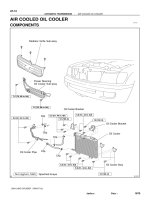
Additional cooler
Automatic transmissions are fitted with a cooler (heat
exchanger) in the lower radiator tank. This transfers
heat from the transmission fluid to the relatively cooler
engine coolant.
A supplementary cooler can be fitted. This extra
cooler will help to extend the life of the transmission
fluid by maintaining it at optimum fluid temperature.
The additional cooler is like a small radiator
(Figure 24.10). It is fitted either in front of or behind
the engine coolant radiator where it can get maximum
air flow.
481-506_May 2chap 24
13/9/06
4:15 PM
Page 488
488 part four automatic transmissions and drive
The filter cannot be serviced and is discarded and
replaced with a new one when the transmission is
being serviced.
Transmission adjustments
1. an outer container – with fins to dissipate heat
Automatic transmissions and their controls are
provided with adjustments. These vary considerably
with different makes and models of vehicle.
The type and method of adjustment will depend on
whether the transmission has full hydraulic control,
or whether it has electronic control. It can also depend
on whether the engine has a carburettor or electronic
fuel injection (EFI).
Because of these differences, and the importance of
correct adjustment, it is essential that detailed information is obtained from the appropriate service manual
before attempting any adjustment on a vehicle.
The importance of checking the basic settings and
adjustments cannot be overstated – many service
complaints can be rectified by attending to the items
outlined below. A transmission simply cannot function
properly unless these are correct.
The following are the types of service adjustments
that are generally provided on automatic transmissions:
2. a powerful magnet – to remove fine steel particles
1. engine idle speed
3. a filter element – to remove foreign particles from
the fluid
2. selector cable, or linkage
4. a bypass valve – which opens if the paper element
becomes clogged.
4. throttle cable or vacuum control (for hydraulic
control)
inlet hose
cooler
outlet hose
figure 24.10
An automatic transmission cooler at the front
of the radiator HOLDEN LTD
Additional filter
Some transmissions are fitted with a replaceable fluid
filter, but a supplementary filter can be fitted in
conjunction with the cooler. The additional filter is
fitted into the cooler line, usually in the flexible line
and close to the transmission cooler for easy access. It
is an in-line filter so all the fluid passing to the cooler
first passes through the filter.
The filter construction is shown in Figure 24.11. It
consists of:
filter
element
magnet to attract
metal particles
3. starter isolator (neutral switch) or range switch
5. throttle-position sensor (for electronic control)
outlet
6. hydraulic pressure
7. brake bands.
Engine idle speed
steel core
polymer
casing
inlet
figure 24.11
by-pass valve
Magnetic in-line filter construction
BOSS
Idle speed is checked with a tachometer and adjusted
to the rpm specified for the vehicle (usually in the
vicinity of 800 rpm).
Adjustment is made with the selector lever in P,
and is finally checked for smooth idling in D. A slight
drop in engine rpm will be noticed when the selector is
moved to D. This is caused by the increased load on
the engine.
High idle speed will cause creep; that is, the vehicle
will move slowly as soon as a gear position is selected,
even with the engine idling. Creep is normal, but it will
be excessive if the idle speed is too high.
High idle speed could also cause a band or brake to
481-506_May 2chap 24
13/9/06
4:15 PM
Page 489
chapter twenty-four automatic transmission service
489
be applied harshly when the selector lever is moved to
a gear position. Low idle speed will cause the engine
to stall.
There are different methods of adjusting the idle on
carburettor and EFI engines, but the effects of
incorrect adjustment are the same.
■ For safety reasons, engine idle or any other engine
adjustments should only be carried out with the
selector lever in the N or P position with the park
brake applied.
Selector cable
The selector cable connects the driver’s selector lever
to the manual valve in the transmission, so that
whenever a gear position is selected, the manual valve
will be moved to that position. For the selector
adjustment to be correct, the selector lever indicator
should be in the N position with the manual valve also
in the N position.
The two ends of a selector cable are shown in
Figure 24.12. The selector lever and its end of the
cable are shown in Figure 24.12(a) and the transaxle
end of the cable and its lever arrangement are shown in
Figure 24.12(b). This is a push–pull cable which
enables the selector lever to move the lever on the
transaxle case in both directions.
A threaded adjustment is provided at the selector
lever. This is adjusted so that the selector positions at
the selector lever correspond with the selector
positions at the transaxle. In the design shown, a roller
and quadrant are used to locate the selector lever in the
various selector positions. Inside the transaxle, a detent
locates the manual valve in its correct positions. The
adjustment is made with the selector lever in N and the
manual valve also in N.
figure 24.12
The starter isolator or neutral switch
This is usually located on the transmission case (Figure
24.13). This is a safety switch, arranged to prevent the
engine from starting in any gear position except N or
P. Incorrect operation of the switch would allow the
engine to be started with the transmission in gear,
causing the vehicle to move out of the control of the
driver.
The isolator switch forms part of the starter
solenoid circuit. It is operated by the gear-selector
mechanism to provide an open circuit in all positions
except N or P. This prevents the starter from operating
in any other position.
Selector lever
(a) lever and selector end of cable (b) transaxle end of cable FORD
■ The isolator switch is also called the neutral switch,
inhibitor switch and sometimes the range selector
switch.
Checking the isolator switch operation
To check that the switch isolates the starter, try to start
the engine with the selector lever in all positions. The
starter should operate in N and P only. Check this while
moving the selector lever backwards and forwards
(within the free play) from N and also from P.
481-506_May 2chap 24
13/9/06
4:15 PM
Page 490
490 part four automatic transmissions and drive
electrical
connector
range switch
mounting bolts
manual control
lever
(a)
figure 24.13
Starter isolator and position switch, rotary
type MITSUBISHI
As a safety precaution, firmly apply the parking
brake and foot brake during the check because the
vehicle could move if the switch is incorrectly
adjusted.
To check the switch itself, the harness connector
will have to be disconnected at the switch and an
ohmmeter used to check between the terminals at the
switch connector. The ohmmeter is connected between
the terminals, and the switch moved to each of the gear
positions.
adjusting nut
manual
control
lever
range switch
(b)
figure 24.14
Manual control lever and range switch
(a) switch assembly (b) cable adjustment
HYUNDAI
Checking the range switch operation
With electronic control, the isolator switch is also a
position switch. It sends signals to the ECU to tell it
which position has been selected. In some vehicles, the
isolator switch is called the range switch. An example
is shown in Figure 24.14.
Some vehicles have the selector positions (or range
positions) shown as indicators on the instrument
cluster (Figure 24.15). With this arrangement, the
range selector switch is used to illuminate the position
that is selected.
When checking the operation of the switch, the
panel indicators should also be checked.
(a) Range indicators
Throttle cable
There are two cables in the accelerator and throttle
cable arrangement. One is the accelerator cable
between the accelerator pedal and the throttle valve in
the throttle body of the engine’s air intake system. The
other is the throttle-valve cable, which connects the
throttle valve to the hydraulic throttle valve (TV valve)
in the transmission.
To avoid confusing the two valves, the throttle
valve in the air intake will be referred to simply as the
malfunction
indicator
indicators
(b) Instrument cluster
figure 24.15
Automatic transmission range indicators on
an instrument cluster HYUNDAI
throttle valve, while the hydraulic valve in the transmission will be referred to as the TV valve.
481-506_May 2chap 24
13/9/06
4:15 PM
Page 491
chapter twenty-four automatic transmission service
An arrangement with two cables is shown schematically in Figure 24.16. When the accelerator pedal is
depressed, the throttle valve is opened by the accelerator cable movement. The transmission downshift
valve and the TV valve are moved by the action of the
throttle cable.
throttle
body
accelerator
accelerator
cable
491
accelerator cable
throttle
body
outer
cable
(a)
throttle valve
(TV valve)
boot
throttle
cable
A
adjustment
plunger
lever
figure 24.16
Throttle cable arrangement
ferrule
HOLDEN LTD
(b)
Throttle linkage adjustment is correct when the
accelerator pedal height, the throttle valve opening,
and the position of the TV valve in the transmission
are in correct relationship.
In general terms, the relationship of these three is as
follows:
1. The pedal should be of sufficient height above the
floor to allow full movement of the linkage.
2. The throttle valve should be closed (at idle
position).
3. The TV valve in the transmission should be at or
near its stop.
The manufacturer’s method of adjustment should
always be referred to, as any errors will affect both the
fluid pressure and the road speeds at which gear
changes occur.
■ Incorrect adjustment, because of low line pressure,
could cause the transmission to slip, resulting in
erratic changes and damage to bands or clutches.
Cable adjustment
The throttle valve ends of both an accelerator cable
and a throttle cable are shown on Figure 24.17. Both
the inner cables operate around quadrants. With this
arrangement, the accelerator inner cable shortens and
the TV valve inner cable lengthens when the accelerator pedal is pressed.
figure 24.17
Throttle cable assembly and adjustment
TOYOTA
To check this particular arrangement, the accelerator cable is checked first: depress the accelerator
pedal and check that the throttle valve is fully open. If
necessary, adjust the length of the cable with the
adjusting nuts until the throttle valve opens fully.
With the accelerator pedal fully depressed, check
that the throttle inner cable has moved out far enough
to expose a stop which is crimped to the inner cable.
The stop should be about 1 mm beyond the end of the
boot on the cable. If necessary, adjust the nuts on
the outer cable to obtain this dimension (A in Figure
24.17(b)).
As with all transmissions with hydraulic control,
the throttle cable adjustment affects throttle pressure in
the transmission and throttle pressure operates on the
shift valves. If the outer cable is lengthened (the inner
cable effectively shortened), then throttle pressure in
the transmission will increase and delay upshifts. If the
outer cable is shortened, this will have the opposite
effect and upshifts will occur earlier.
In the transmission, throttle pressure operates on
the regulator valves as well as on the shift valves. This
means that both line pressure and converter pressure
can be affected by throttle cable adjustment. If line
pressure is too high, the shifts will be harsh as well as
481-506_May 2chap 24
13/9/06
4:15 PM
Page 492
492 part four automatic transmissions and drive
late. If the pressure is too low, upshifts will be early
and clutches or bands could slip.
Vacuum control
A vacuum control unit is shown in Figure 24.18. This
performs a similar function to the throttle linkage.
figure 24.18
Vacuum-operated throttle valve
1 line pressure, 2 throttle pressure, 3 throttle
pressure, 4 exhaust
The unit, which is mounted on the transmission case,
consists of a diaphragm in a sealed container connected
by a pipe to the engine manifold. The diaphragm is
under the influence of engine manifold vacuum and
therefore is sensitive to variations in engine load.
A pushrod from the diaphragm extends into the
transmission and operates the throttle valve (TV
valve). Changes in throttle butterfly opening and
engine load will therefore affect throttle pressure,
which will determine when gearshifts occur. (Line
pressure will also be affected.)
Adjustment, if necessary, can be made either by
changing the length of the pushrod between the
diaphragm and the throttle valve or by turning a small
screw located inside the vacuum connection.
Kickdown
Where a throttle cable is used, the downshift valve is
operated by the cable and no adjustment is required.
Where vacuum control is used, forced downshifts
are obtained by means of a kickdown switch operated
by the accelerator linkage, and a solenoid which
controls a downshift valve in the transmission
(Figure 24.19).
When the accelerator pedal is depressed to the
floor, the switch contacts are closed, the solenoid is
energised and downshift pressure is provided to the
shift valves to force a downshift. An adjustment is
provided on the switch or the linkage, and this can be
altered if the switch does not operate.
figure 24.19
Kickdown (downshift) switch and solenoid
MAZDA
Throttle-position sensor
The throttle-position sensor, used with electronic
control, is attached to the throttle body. The sensor can
usually be adjusted, within limits, by loosening the
screws and altering its position.
There are two basic types of sensors: one is a
rheostat and the other is a switch. The rheostat provides a voltage signal that varies with throttle opening.
It is basically a variable resistance, so can be checked
with an ohmmeter (Figure 24.20). Its resistance should
vary between closed-throttle and full-throttle positions.
The switch-type sensor provides signals in a
number of steps. It is actually a switch with a number
of contacts. For checking purposes, it can be treated in
the same way as any other switch.
Brake band adjustments
These are carried out to compensate for wear of the
band lining. A loosely adjusted band could slip,
resulting in overheating and excessive wear. A tightly
adjusted band will cause binding, again resulting in
overheating and wear. Correct adjustment provides a
small clearance between the brake band and the drum.
481-506_May 2chap 24
13/9/06
4:15 PM
Page 493
chapter twenty-four automatic transmission service
electrical
connector
ohmmeter
493
inside the transmission. The oil pan has been removed
and a small tension wrench is being used on the screw
adjuster. In most transmissions the band is adjusted by
tightening the adjusting screw to a specified torque and
then backing the screw off a specified number of turns.
Gauge blocks are sometimes used.
External adjustment
The adjustment shown in Figure 24.22 is an external
adjustment, which is accessible after removing the
outside cover from the servo.
plenum
chamber
figure 24.20
throttle
body
Checking the throttle-position sensor
HYUNDAI
This enables the band to be applied smoothly and
firmly, with minimum wear occurring.
Some transmissions have two band adjustments
while others have only one. Some automatic transmissions have disc brakes instead of bands, and these
have no adjustments.
■ The band adjuster may be internal or external.
Internal adjustments can only be carried out after
the oil pan has been removed.
Internal adjustment
Figure 24.21 shows a band adjustment being carried
out on a transmission; in this case, the adjustment is
figure 24.22
Servo and band with an external adjustment
The following is an example of how a band is
adjusted:
1. Loosen the locknut.
2. Holding the servo piston to prevent it from turning,
tighten the adjusting screw to 10 Nm and then back
it off. Repeat this twice. This is done to seat the
band snugly on the drum and so prevent a false
reading when adjusting.
3. Tighten the adjusting screw to 5 Nm and then back
it off 31/2 turns.
4. Tighten the locknut to 15 to 20 Nm.
Fault diagnosis and checks
An understanding of the construction and operation of
the particular type of transmission or transaxle is
necessary to enable faults to be diagnosed and checks
to be made. While the general operating principles of
most transmissions are similar, the details vary greatly.
figure 24.21
Servo and band with an internal adjustment
MITSUBISHI
■ Vehicle manufacturers provide diagnosis guides,
and these should be referred to whenever a fault is
suspected.
481-506_May 2chap 24
13/9/06
4:15 PM
Page 494
494 part four automatic transmissions and drive
Basic checks
Where an automatic transmission has an operational
problem, there are a number of preliminary checks that
can be carried out. These will provide information and
possibly correct minor problems.
1. Fluid level. Check the fluid level, top up if
necessary and check for external leaks.
2. Fluid condition. Check the fluid for deterioration
and contamination.
readings are taken for different operating conditions
(Figure 24.23).
As an example, specifications for line pressure
could be: 350 kPa at idle and 700 kPa at 1000 rpm.
These tests would be taken with the selector in
D position. The pressure in reverse could be up to
1000 kPa.
■ Pressure readings can also be taken during road
tests.
3. Engine idle. Check and adjust the engine idle speed
to specifications.
4. Throttle cable or linkage. Check for free operation
and ensure that there is no lost motion. Adjust to
specifications. Check to ensure full throttle is
available.
5. Selector linkage. Check operation of linkage and
starter neutral switch.
6. Electronic controls. Check ECU self-diagnosis for
faults.
7. Electrical connections. Check all electrical connections associated with the transmission sensors
for looseness or corrosion.
figure 24.23
8. Battery terminals. Check both battery terminals for
looseness or corrosion.
It is important that these checks are carried out,
because the checks, and related adjustments, will
correct many of the less serious operating problems.
■ The checks should be made and the vehicle road
tested before any internal repairs are considered.
In addition to the above, band adjustments can be
carried out. Where this entails removing the oil pan, as
much diagnosis as possible should be carried out
before this is done. This will enable the transmission to
remain operational until a decision on the problem is
reached. Dismantling, if considered necessary, can
then be carried out.
Where further diagnosis is needed, a pressure test
or a stall test can be carried out.
For a transmission with electronic control, test
instruments would be used to extract self-diagnosis
information from the ECU (see later sections).
Pressure check
A pressure check can be carried out as an aid to
diagnosing hydraulic problems. For this test, a pressure
gauge is connected to the transmission, and pressure
Oil pressure gauge connected to check the
line pressure of a transaxle
Stall test
A stall test checks the engine, the torque converter and
the transmission by measuring the maximum rpm that
the engine can produce with the turbine held in a
stalled condition.
To make the test, the vehicle is held stationary with
brakes and wheel chocks, the selector lever is placed in
D, and the throttle is opened fully for a very short
period. The test conditions are shown in Figure 24.24.
A tachometer connected to the engine registers the
engine rpm, and this is used to interpret engine and
transmission condition. As well as this, a pressure
gauge can be connected to the transmission to check
the system fluid pressure.
The tachometer reading is specified by the manufacturer, for example 1450 rpm to 1750 rpm, although
these figures will vary for different engines. If the
tachometer reading comes within these figures, then
the transmission and converter are satisfactory.
A low rpm reading can indicate that the engine is
suffering from loss of power, a clogged exhaust, or it
can be caused by a slipping stator in the converter
which is placing a greater than normal load on the
engine.
481-506_May 2chap 24
13/9/06
4:15 PM
Page 495
chapter twenty-four automatic transmission service
495
figure 24.24
Stall testing an automatic transmission
1 chock the wheels, 2 apply parking brake, 3 connect tachometer, 4 select D, 5 apply brakes and open throttle –
stall test only if allowed by manufacturer
A high rpm reading can be caused by slipping
bands and clutches or mechanical damage in the
converter. In either case, further investigation is
necessary to isolate the problem.
Information should be obtained from the appropriate workshop manual before a stall test is attempted.
It should be realised that stall testing generates high
fluid temperatures and places severe loadings on all
parts of the transmission and drive line as well as on
the engine.
Some manufacturers recommend against stall
testing and others allow partial stall testing only.
A stall test should be performed only during
diagnosis, and then only when permitted for the
particular transmission.
Checks are made at different throttle openings and at
different speeds, with the selector lever in different
positions.
Road testing
Smooth engagement
When road testing a vehicle with an automatic
transmission, checks are made of:
The bands should be applied smoothly when the
selector lever is moved through the various positions.
Reverse may be a little harsher, as higher fluid
pressures are often used.
1. selector lever operation (including the isolator switch)
2. the shift pattern (road shift speeds)
3. the shift quality (engine overspeeding between
shifts, or slippage)
4. noise in the transmission.
■ Before commencing a road test, check correct
operating temperature, engine idle and fluid level.
General test procedures
The general procedure for a road test is illustrated in
Figure 24.25.
During a road test, observe the following points.
Starter isolator switch
The starter should operate only in N or P positions.
This is an important safety feature that must be
checked.
Upshifts
Upshifts should be checked on a level road to
determine if they occur at the correct road speeds.
481-506_May 2chap 24
13/9/06
4:15 PM
Page 496
496 part four automatic transmissions and drive
figure 24.25
Checks that can be made during a road test of an automatic transmission or transaxle
Checks should be made at minimum throttle, full
throttle and kickdown positions. The shifts should
occur at the speeds specified by the vehicle
manufacturer. (Refer to Table 24.1 for examples of
shift speeds. The table is for a transmission with a
hydraulic governor.)
481-506_May 2chap 24
13/9/06
4:15 PM
Page 497
chapter twenty-four automatic transmission service
Downshifts
Downshifts occur at lower speeds than upshifts. These
can be checked at closed throttle, and, where suitable
conditions are available, at full or part throttle on hills
to check downshifts under load. Forced downshifts
(kickdown) can also be checked.
Overdrive
For transmissions with overdrive or similar switches,
gearshifts can be checked with the overdrive switch
both on and off. With the overdrive switch off, there
should be no upshifts from third to fourth gear. When
the switch is turned on at higher speeds, the
transmission should shift from third to fourth.
Power and economy modes
For transmissions with electronic control that have
power and economy modes of operation, the shift
speeds can be checked in both modes. There may not
seem to be much variation in road speeds, but the
power indicator lamp should light with the power
mode selected.
Shift quality
The shifts should be checked for both harshness and
slip. This should be done under light-load and also
heavy-load conditions. Checks can be made both on a
level road and on hills. Any tendency for the engine to
overspeed during shifts can also be observed.
Low and second positions
Select 1, and check that upshifts do not occur. Do not
overspeed in this gear. Position 2 can be selected with
the vehicle stopped and then changes observed from 1
to 2 as vehicle speed is increased.
Parking pawl
With the vehicle stopped on a hill, select P and release
the brakes to check that the parking pawl will hold.
The brakes should be reapplied before moving the
selector lever from the park position.
Reverse
With the vehicle stopped, select R and check for slip
and noise. Some additional gear noise is not unusual in
reverse.
Shift patterns
The road speed at which the various gearshifts occur is
determined by the governor (hydraulic control), the
497
road-speed sensor (electronic control) and the amount
that the accelerator is depressed by the driver.
Road-speed checks are made at defined throttle
openings. In some transmissions, three positions are
checked: light throttle, full throttle and kickdown.
Other transmissions have shift patterns specified for
different throttle positions, such as quarter, half and
full throttle. Percentage of throttle opening is also
used, for example shift speeds at 5% and 80%. The
shift speeds should be within the specifications for the
particular transmission.
With hydraulic control, the shift speeds can be
corrected by adjusting the throttle linkage or by
altering the length of the pushrod where a vacuum
control is fitted.
With electronic control, the shift patterns are
embedded in the memory of the ECU. With an
electronically controlled transmission a shift-speed
problem is therefore more likely to be related to the
throttle-position sensor or road-speed sensor rather
than to hydraulics.
On most transmissions the driver can alter the shift
pattern by the use of a power/economy switch. When
the transmission is in economy mode the upshifts will
generally occur earlier than they would when in power
mode.
Adaptive Learning Strategy
Some transmissions employ an adaptive learning
strategy. This has the capability of automatically
modifying the programmed shift pattern to suit the
driving habits of each individual driver. This has to be
considered when road testing a transmission with this
feature.
An ECU with this program receives information
from sensors which enables it to monitor parameters
such as steering wheel turn, vehicle speed, throttle
operation, brake operation, gearshift mode, engine rpm
etc. The ECU recognises the combination of these
parameters as a distinctive pattern for each driver and
adjusts the shift pattern to suit that individual.
As a simple example, a driver might use more throttle
when taking off in an attempt to accelerate more quickly.
The ECU recognises this aspect and will delay the
upshifts for that driver resulting in a quicker get-away.
As another example, another driver might drive
cautiously when descending hills or approaching
corners. The ECU recognises this aspect and will
change the shift pattern to earlier downshifts which
slow the vehicle due to increased engine braking.
481-506_May 2chap 24
13/9/06
4:15 PM
Page 498
498 part four automatic transmissions and drive
■ See the previous chapter for more information on
electronic control of shift patterns.
Table of shift speeds
Table 24.1 is one example of the shift pattern for a
transmission, but they can be shown in a variety of
ways, including a graph. The shift speeds listed for a
transmission should be treated as approximate speeds,
not as exact speeds. ‘Light throttle’ means just
sufficient accelerator movement to cause the vehicle to
increase speed. ‘Full throttle’ occurs when the
accelerator is pressed almost to the floor, and ‘kickdown’ is when the accelerator is fully depressed. In
some vehicles, there is a resistance to movement
between full throttle and kickdown. In other vehicles,
kickdown operates the kickdown switch and solenoid.
table 24.1
Table of shift patterns
THROTTLE
Light
Full
Kickdown
Closed
Full
Kickdown
and electronic controls must all be considered. Table
24.2 shows these and indicates some of the things that
might cause problems in the different locations. As an
example, do not immediately blame the transmission
for a problem that could be caused by the engine not
performing properly.
■ It is also possible that a faulty torque converter
could cause what appears to be poor engine
performance.
table 24.2
General location of automatic transmission
problems
LOCATION
POSSIBLE PROBLEMS
Engine
Lack of power
Engine needs tune-up
Idle speed incorrect
Torque converter
Low pressure
Converter lock-up clutch fault
Stator OWC stuck or slipping
Mechanical/power
train
Cables or linkage
Band adjustment
Band worn
Clutch faulty
Transmission OWC slipping
Gearing damaged or noisy
Hydraulic system
Cable adjustment
Low pressure
Valves sticking
Fluid leaks
Leaking solenoid valve
Governor or valve faulty
Clutch piston
Servo
Electronics/electrics
Isolator switch or position
Sensor switch faulty or needs
adjusting
Electrical cable fault
Connector making poor contact
Road-speed sensor fault
Throttle sensor adjustment or
fault
Other sensor fault
Solenoid not operating
ECU fault
Loose or dirty battery terminals
Low alternator output
SHIFT SPEEDS (KM/H)
UPSHIFT
1–2
UPSHIFT
2–3
UPSHIFT
3–4
12–20
40–45
45–55
21–30
60–70
70–90
35–40
80–90
DOWNSHIFT
2–1
DOWNSHIFT
3–2
DOWNSHIFT
4–3
5
10
35
20
20–25
60–70
25–30
30–35
■ During road-speed checks, speed should be kept
within the legal speed limit for the area in which
the vehicle is being driven. Road testing is
distracting to the driver so extra care is required.
Diagnosing problems
Workshop manuals provide diagnosis guides and
charts which should be referred to whenever a problem
arises. These guides are often very extensive, with
some providing step-by-step procedures.
In the event of a problem, the basic checks should
be carried out, as previously discussed, so that the
simpler things are checked and eliminated first. If the
problem has still not been cured, the more difficult
things can be investigated.
When diagnosing an automatic transmission
problem, the engine, power train, hydraulic controls
A general diagnosis guide is shown in Table 24.3.
This is not designed for any particular transmission.
However, it can be used to identify the types of
problems that can occur with automatic transmissions.
481-506_May 2chap 24
13/9/06
4:15 PM
Page 499
chapter twenty-four automatic transmission service
table 24.3
Diagnosis guide for an automatic transmission
PROBLEM
POSSIBLE CAUSES
No starter operation in N or P
Starter operates in other
than N or P
No engagement in D
No engagement in any
selector position
Delayed engagement
Slip or noise on take-off in D
9, 31, 41
9, 31
20, 9, 21, 24
9, 21, 16, 32, 8, 20
24, 21, 11, 31, 33, 42, 43
20, 11, 25, 16, 15, 17,
28, 36, 37
Slip or noise on take-off in
20, 11, 21, 25, 16, 15,
reverse
17, 28, 36, 37
Harsh engagement all positions 1, 11, 24, 25, 23, 36, 37
Poor acceleration in first
2, 4, 14, 15, 16, 17
Poor performance and
2, 3, 30
overheating in third
No 1–2 shift
6, 17, 29, 34, 36, 42, 43
Slip during 1–2 shift
20, 11, 25, 16, 17, 15,
sometimes
27, 21, 36, 42, 43
Harsh 1–2 shift
11, 24, 25, 23, 36, 37,
32, 42
No 2–3 shift sometimes
9, 15, 27, 29, 34, 32, 36,
42, 43
Slip during 2–3 shift
20, 11, 24, 21, 36, 42, 43
Harsh 2–3 shift
11, 24, 23, 36, 37, 42, 43
Soft shifts
21, 16, 17, 11, 36, 37, 40
No 3–4 shift
39, 32, 15, 16, 17, 29,
32, 36, 42, 43
Shift speeds incorrect
11, 24, 28, 29, 33, 40,
42, 43
No engine braking in 1 position 16, 17, 27
Whine in N with engine running 13
Grating noise from transmission 12, 18, 19
Knocking noise from converter 4, 5, 8
Park will not hold
9, 12
Transmission overheating
30, 20, 3
No converter clutch lock-up
5, 6, 8, 24
Transmission binds
27, 16, 22, 26
Engine stalls
1, 2
Engine flare between shifts
22, 16, 17, 20, 42, 43
Vehicle has excessive creep
1
No forced downshift
11, 38
Diagnosing electronic control problems
Transmissions with electronic control have a selfdiagnosis program in the ECU which can diagnose
faults as they occur during operation.
If a sensor or component of the electronic control
system is not functioning properly, then it will send
abnormal signals to the ECU. When the ECU receives
an incorrect signal, its self-diagnosis program
recognises that the signal is not normal and records a
fault in that part of the system. In most cases, the
information will remain in the memory of the ECU
until the battery is disconnected.
table 24.3
499
Diagnosis guide for an automatic transmission
(continued)
KEY TO POSSIBLE CAUSES
Engine
1. Idle speed
2. Lack of power
Torque converter
3. Stator OWC stuck
4. Stator OWC not locking
5. Converter clutch
6. Pressure low
7. Converter solenoid
inoperative
8. Converter damage
Mechanical/power train
9. Selector cable or
linkage adjustment
10. Inhibitor switch
adjustment, or fault
11. Throttle cable or
linkage adjustment
12. Parking pawl or
mechanism damaged
13. Oil pump worn or
damaged
14. Transmission OWC not
locking
15. Clutch plates worn
16. Band adjustment
17. Brake bands or plates
worn
18. Gearing worn or
damaged
19. Worn bearings or
thrusts
Hydraulic system/controls
20. Fluid level low
21. Low line pressure
22. Internal fluid leaks
23. High line pressure
24. Valves sticking
25. Vacuum control fault or
leak
26. Clutch piston sticking
27. Servo piston
28. Governor valve sticking
29. Shift valves sticking
30. Cooler inefficient or
line blocked
Electronics/electrics
31. Isolator/selectorposition switch
adjustment, or fault
32. Wiring or connectors
33. Throttle-position
sensor adjustment,
or fault
34. Speed-sensor fault
35. Oil-temperature
sensor
36. Shift solenoid
37. Pressure-regulator
solenoid
38. Kickdown switch or
solenoid
39. OD switch fault
40. ECU fault
41. Anti-theft system
armed
42. Loose or corroded
battery terminal
43. Low alternator
output
The ECU provides fault information in the form of
codes. Depending on the system, these are obtained
from it by means of a voltmeter, an LED test lamp, or
specialised test equipment such as a scan tool. In some
cases, the transmission power-mode lamp on the
instrument panel can be used for diagnosis.
To obtain the codes, the vehicle must have been
operated so that the fault is recorded. The test equipment is then connected into the system, usually by
means of special connecting cables into a diagnosis
connector provided for the purpose. The ignition
switch is turned on, but the engine is not running.
481-506_May 2chap 24
13/9/06
4:15 PM
Page 500
500 part four automatic transmissions and drive
Diagnosis codes
The codes are given numbers, and these are interpreted
by the operator from the way in which the light glows,
the way in which the pointer of a voltmeter flicks, or
from the test instrument. Specialised testers can show
the code, or a pulse pattern trace, or other information
on a liquid-crystal display panel.
LED codes
Figure 24.26 shows how an LED test lamp can signal
code numbers from the ECU. Each flash of light from
the LED represents a single digit, so code No. 1 is
shown by a single flash of light which lasts for one-third
of a second. This is the normal condition, and code No.
1 shows that there are no faults recorded. The light will
flash the code again after three seconds, and will
continue to do so as long as the test lamp is connected.
figure 24.26
No. 3, faults
table 24.4
Diagnosis codes
CODE NO.
NUMBER OF
FLASHES
MEANING
1
2
3
4
5
6
7
1
2
3
4
5
6
7
Normal operation, no faults
Vehicle-speed sensor No. 1
Solenoid No. 1, or wiring
Solenoid No. 2, or wiring
Throttle-position sensor
Shift-position switch
Vehicle-speed sensor No. 2
Scan tool
Figure 24.27 shows a special tester or scan tool which
is used to obtain diagnosis codes and other
information. This is connected to the data link
connector (DLC). The same tester is used for
diagnosing problems in the engine’s electronic fuelinjection system and other electronic systems of the
vehicle.
Diagnosis faults shown by an LED test lamp
(a) code No. 1, normal (b) codes No. 2 and
DLC
DAIHATSU
scan tool
For code No. 2, there will be two flashes close
together. These are one second apart and are followed
by a pause of three seconds before the code is
repeated. If there is more than one fault in the memory,
a different code will follow. The codes will appear in a
sequence starting with the smallest number and
finishing with the largest.
Table 24.4 is an example of the information
provided by the code. It shows the diagnosis code
number, the number of flashes of the LED, and the part
of the system that has the fault. Having read the code
number, the table is then used to interpret the code.
This table, with its seven codes, is a relatively simple
one. Some transmissions have many more diagnosis
codes.
figure 24.27
Scan tool tester connected to a data link
connector (DLC) to check for automatic
transmission problems HYUNDAI
Indicator lamp
Another method of displaying codes is shown in
Figure 24.28. In this transmission, the power indicator
lamp is used to flash out the code number.
Components
While the self-diagnosis tests identify the section of
the system that has a fault, further testing is needed to
isolate the fault to the sensor, connector, wiring or
other particular part of the system. A voltmeter is used
to check the voltage at particular connectors, and an
481-506_May 2chap 24
13/9/06
4:15 PM
Page 501
chapter twenty-four automatic transmission service
501
Transmission overhaul
A transmission will have to be dismantled and overhauled if a major problem exists. This requires
specialised knowledge, special tools and the appropriate workshop manual to carry out satisfactory
repairs.
Transmission overhaul is beyond the scope of this
chapter, but the following illustrations show the construction of some transmissions. These enable the
internal parts to be identified.
■ When a new or overhauled transmission is fitted,
relearn procedures as specified by the manufacturer
should be followed. See the information on adaptive
learning strategy earlier in the chapter.
Transmission construction
figure 24.28
Fault code from the power indicator light
(a) first long flash and second short flash
indicates speed-sensor circuit fault (b) simplified speedsensor circuit with a sensor in the speedometer head
ohmmeter is used to check the resistance of components or other parts of the circuit.
■ Only recommended testing equipment should be
used. Other test equipment that draws too high a
current can damage the ECU. The allowable
current is only a few milliamps. A normal test lamp
with an incandescent bulb should not be used with
electronic components.
Fail-safe function
If a fault occurs in a part of the electronic control
system which will affect the driveability of the vehicle,
then the fail-safe function comes into operation. The
ECU will place the faulty part of the system in the
default mode. This means that instead of a variable
signal from the sensor, a fixed signal will be used. The
transmission will continue to operate, but not as
efficiently as it normally would. In the workshop, the
self-diagnosis function can be used to identify the
problem.
■ The fail-safe function is sometimes referred to as
the limp-home mode.
There are many variations in automatic transmission
design and the illustrations that follow are examples.
Figure 24.29 is a sectional view of an electronically
controlled, four-speed automatic transmission for a
rear-wheel-drive vehicle. This transmission has two
epicyclic gear sets which, when directed by the ECU
(in this case the power control module (PCM)), provide four forward gears and a reverse gear. The
transmission has five clutch packs, one brake band,
one sprag type one-way clutch and one roller type oneway clutch. The transmission has a lock-up torque
converter.
Another example is shown in Figure 24.30. This
unit is basically a three-speed transmission with an
overdrive unit for fourth gear.
Figure 24.31 is a sectional view of an automatic
transaxle. This is a three-speed transaxle with two
separate gear sets with a common sun gear. As well as
the planetary gearing, the idler gear, final-drive gear
and differential assembly can be seen. This has fewer
parts than a four-speed transaxle, so it is easier to
identify the parts in this illustration.
A four-speed transaxle is shown in Figure 24.32.
This has compound planetary gearing, four multiplate
clutches, two brakes and two one-way clutches to
provide the four forward gears and reverse. It has a
converter clutch and electronic control.
Transmission and transaxle parts
To gain familiarity with the parts and construction of
automatic transmissions, the illustrations should be
used to identify the main parts. As a guide, look for the
481-506_May 2chap 24
13/9/06
4:15 PM
Page 502
502 part four automatic transmissions and drive
5
3
1
2
21
23
22
7
4
6
19
20
9
8
17
12
14
16
18
11
10
13
15
figure 24.29
A four-speed automatic transmission with electronic control
1 case, 2 reverse input clutch, 3 input clutch housing, 4 overrun clutch, 5 forward clutch, 6 forward clutch sprag
assembly, 7 3–4 clutch, 8 input planetary gear set, 9 low and reverse clutch, 10 low roller clutch, 11 reaction planetary gear set,
12 output shaft, 13 speed sensor, 14 parking pawl, 15 park lock actuator, 16 control valve assembly, 17 manual shaft, 18 inside
detent lever, 19 2–4 band, 20 pump assembly, 21 stator roller clutch, 22 torque converter, 23 turbine shaft HOLDEN LTD
following: torque converter parts, lock-up clutch, input
shaft, output shaft, gearing, clutches, brakes and bands,
one-way clutches, final drive and gears, parking pawl
and gear, oil pump, valve-body assembly.
Review questions
1.
How is the fluid level checked in an automatic
transmission?
2.
What precautions are needed when draining the
fluid from an automatic transmission?
3.
What information can be gained from the fluid
on the dipstick?
4.
Why must the correct type of fluid be used?
5.
What are the different types of fluids?
6.
Name some of the properties of automatic
transmission fluid, and indicate why the fluid
has these properties.
7.
What effect does excess transmission fluid
temperature have on the transmission?
8.
What is the effect of incorrect engine idle speed
on a vehicle with automatic transmission?
Technical terms
Degrade, degradation, deposits, topping up, automatic transmission fluid, ATF, Dexron, viscosity
index, oxidation, foaming, extreme-pressure
additives, chemical action, detergent, fluid odour,
discoloration, contamination, isolator switch,
selector cable, throttle cable, creep, vacuum control,
kickdown, line pressure, electronic controls,
throttle-position sensor, converter pressure, rheostat,
power mode, diagnosis codes, stall test, road test,
shift pattern, shift speeds, shift quality, selfdiagnosis, fail-safe, default mode, adaptive learning
strategy.
481-506_May 2chap 24
13/9/06
4:15 PM
Page 503
chapter twenty-four automatic transmission service
503
figure 24.30
Automatic transmission with overdrive
1 converter housing, 2 torque converter, 3 oil pump, 4 overdrive planetary gears, 5 direct clutch, 6 drum support,
7 intermediate shaft, 8 second brake band, 9 front clutch, 10 rear clutch, 11 front planetary gears, 12 rear planetary gears,
13 one-way clutch, 14 disc brake, 15 transmission case, 16 governor, 17 extension housing, 18 output shaft, 19 oil distributor,
20 valve-body assembly, 21 oil pan, 22 overdrive brake band, 23 overdrive case, 24 input shaft, 25 overdrive cancel solenoid MAZDA
9.
What are the likely problems if the selector
linkage is not correctly adjusted?
10.
What is the purpose of the isolator or neutral
switch?
11.
12.
How can the operation of the isolator switch be
checked?
What is the purpose of the throttle cable and
what does it operate?
13.
How would incorrect adjustment of the throttle
cable affect transmission operation?
14.
What is the purpose of a vacuum control?
15.
When is a throttle-position sensor used?
16.
Generally, how is a band adjustment carried
out?
17.
What would be the effect of a faulty band
adjustment?
18.
What are some of the basic checks that should
be carried out if an automatic transmission is not
operating properly?
19.
What is meant by diagnosis?
20.
What is the function of the road-speed sensor?
21.
State the main checks that would be made during
the road test of an automatic transmission.
22.
How could the parking pawl be checked?
23.
What are the power mode and economy mode?
24.
What is adaptive learning strategy as applied to
the shift pattern of an automatic transmission?
25.
Name the different sections of an automatic
transmission that would be considered when
locating a fault.
481-506_May 2chap 24
13/9/06
4:15 PM
Page 504
504 part four automatic transmissions and drive
figure 24.31
Sectional view of an automatic transaxle
1 transaxle case, 2 rear clutch, 3 front clutch, 4 connecting shell, 5 front ring gear, 6 front planet carrier, 7 sun
gear, 8 low and reverse brake, 9 one-way clutch, 10 one-way clutch inner race, 11 rear planet carrier, 12 rear ring gear and
hub assembly, 13 bearing housing, 14 output gear, 15 turbine shaft, 16 oil pump shaft, 17 bearing cover, 18 oil seal, 19 torque
converter, 20 converter housing, 21 oil seal, 22 speedometer drive gear, 23 side gear, 24 pinion, 25 pinion shaft, 26 differential
gear case, 27 final-drive gear, 28 oil seal, 29 side-bearing housing, 30 control valve assembly, 31 oil pan, 32 oil pump, 33 band
FORD
481-506_May 2chap 24
13/9/06
4:15 PM
Page 505
chapter twenty-four automatic transmission service
figure 24.32
505
Four-speed automatic transaxle in part section
1 coasting clutch, 2 forward clutch, 3 reverse clutch, 4 reverse and forward drum, 5 3–4 clutch, 6 2–4 brake
band, 7 low and reverse brake, 8 output gear, 9 idler gear, 10 differential, 11 parking pawl, 12 throttle cable, 13 control body,
14 oil pump, 15 inhibitor switch, 16 pulse generator, 17 fluid-temperature switch MAZDA