Dynaform DF5 9 2 1 hot forming training tutorial
Bạn đang xem bản rút gọn của tài liệu. Xem và tải ngay bản đầy đủ của tài liệu tại đây (804.83 KB, 41 trang )
Hot Forming
Training Tutorial
Version 5.9.2.1
Engineering Technology Associates, Inc.
1133 E. Maple Road, Suite 200
Troy, MI 48083
Tel: +1 (248) 729 3010
Fax: +1 (248) 729 3020
Email:
Engineering Technology Associates, Inc., ETA, the ETA logo, and eta/DYNAFORM are the registered
trademarks of Engineering Technology Associates, Inc. All other trademarks or names are the property
of the respective owners.
©1998-2014 Engineering Technology Associates, Inc. All rights reserved.
FOREWORD
FOREWORD
The concepts, methods, and examples presented in this text are for illustrative and educational
purposes only, and are not intended to be exhaustive or to apply to any particular engineering problem
or design.
This material is a compilation of data and figures from many sources.
Engineering Technology Associates, Inc. assumes no liability or responsibility to any person or
company for direct or indirect damages resulting from the use of any information contained herein.
eta/DYNAFORM Application Manual
I
OVERVIEW
OVERVIEW
The eta/DYNAFORM software package consists of four programs. These programs represent the
pre-processor, solver and post-processor. They are: eta/DYNAFORM, eta/Job Submitter, eta/POST
and eta/3DPlayer.
eta/DYNAFORM is the pre-processor portion of the software package, which is used to construct the
sheet metal forming models. It includes VDA and IGES translators for importing line data and a
complete array of tools for altering or constructing line data and meshing it.
LS-DYNA is the software package’s solver. eta/DYNAFORM has a complete LS-DYNA interface
allowing the user to run LS-DYNA from eta/DYNAFORM.
eta/POST and eta/GRAPH are the post-processing portions of the package. These programs are used
to post-process the LS-DYNA result files from the analysis. eta/POST creates contour, deformation,
FLD, and stress plots and animations with the result files. eta/GRAPH contains functions for
graphically interpreting the same results.
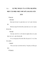
eta/POST
(post-processor)
eta/DYNAFORM
LS-DYNA
(pre-processor)
(solver)
eta/3DPlayer
(post-processor)
Figure 1: Components of eta/DYNAFORM solution package.
Each of the software components has its own manual which should be referenced for further
information on running these programs. These manuals are:
eta/DYNAFORM Application Manual
A comprehensive training manual for using the
eta/DYNAFORM software package for various
applications.
eta/DYNAFORM User’s Manual
A reference guide to the functions contained in
the eta/DYNAFORM program (pre-processor).
LS-DYNA Keyword User’s Manual
A reference guide to the LS-DYNA program
(solver).
eta/POST User’s Manual
A reference guide to the functions contained in
the eta/POST program and eta/GRAPH
program (post-processor).
II
eta/DYNAFORM Application Manual
TABLE OF CONTENTS
TABLE OF CONTENTS
FOREWORD................................................................................................................ I
OVERVIEW ............................................................................................................... II
TABLE OF CONTENTS .......................................................................................... III
Hot Forming Analysis - B Pillar ................................................................................. 1
Create an eta/DYNAFORM Database ...................................................................................... 2
I.
Start eta/DYNAFORM 5.9.2.1···································································· 2
II.
Open the Database ·················································································· 2
HOT FORMING SETUP ........................................................................................................... 4
I.
New Hot Forming Setup ··········································································· 4
II.
General ······························································································· 5
III. Blank Definition ···················································································· 5
IV. Blank Material and Property Definition ························································· 8
V.
Tools Definition ····················································································10
VI. Tools Material Definition ·········································································14
VII. Tools Positioning ··················································································15
VIII. Process Definition ·················································································18
IX. Control Parameters ················································································20
X.
Animation ···························································································21
XI. Gravity Loading ····················································································23
XII. Press Hardening ····················································································25
XIII. Submit Job ··························································································27
POST PROCESSING (with eta/POST) ................................................................................... 29
I.
Reading the Results File into the Post Processor ··············································29
II.
Deformation ························································································30
III. Thinning·····························································································31
IV. View Temperature Distribution ··································································32
MORE ABOUT eta/DYNAFORM 5.9.2.1 ............................................................... 34
CONCLUSION .......................................................................................................... 35
eta/DYNAFORM Application Manual
III
Hot Forming Analysis - B Pillar
1. Hot Forming Analysis - B Pillar
eta/DYNAFORM Application Manual
1
Hot Forming Analysis - B Pillar
Create an eta/DYNAFORM Database
I. Start eta/DYNAFORM 5.9.2.1
For workstation/Linux users, enter the command “df5921” (default) from a UNIX shell to start
eta/DYNAFORM5.9.2.1. For PC users, double click the eta/DYNAFORM5.9.2.1 (DF5921) icon from
the desktop or choose eta/DYNAFORM from the program group.
After starting eta/DYNAFORM, a default database Untitled.df is created. The user needs to import
CAD or CAE model to the database to start working.
II. Open the Database
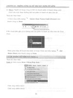
From the menu bar, select FileOpen to open the Open File dialog box, as illustrated in Figure 1.1.
Select the database file HotForming.df and click Open to display the model illustrated in Figure 1.2.
Figure 1.1
2
Open file dialog box
eta/DYNAFORM Application Manual
Hot Forming Analysis - B Pillar
Figure 1.2
eta/DYNAFORM Application Manual
Opened Model
3
Hot Forming Analysis - B Pillar
HOT FORMING SETUP
After finishing the preparation of model, click the Hot Forming from AutoSetup menu to display Hot
Forming Setup.
Figure 1.3
AutoSetup menu
I. New Hot Forming Setup
Clicking Hot Forming menu, the New Hot Forming dialog box appears for the user to define the basic
setup parameters, as illustrated Figure 1.4.
Figure 1.4
4
Sheet Forming Setup dialog box
1.
Input blank thickness:1.95 (mm).
2.
Select process type: Single Action.
3.
Select original die face: Upper &Lower.
4.
Click OK to display the Hot Forming interface.
eta/DYNAFORM Application Manual
Hot Forming Analysis - B Pillar
II. General
After entering General interface, the program will automatically create three stages: Gravity, Forming
and Hardening. As the tool defined in the forming stage is cited in the gravity and hardening stages,
the user is allowed to define the blank and tool from the forming stage, as illustrated in Figure 1.5.
You do not need to modify any parameters except for changing the Title into Forming. See Figure
1.5.
Figure 1.5
General interface
III. Blank Definition
1.
Enter the Blank interface, and click the Blank tab to display the Blank Definition interface.
eta/DYNAFORM Application Manual
5
Hot Forming Analysis - B Pillar
2.
Then, click the Define geometry button from Geometry field in the blank definition
interface. See Figure 1.6.
Figure 1.6
3.
The Blank Generator dialog box illustrated in Figure 1.7 is displayed.
Figure 1.7
6
Define blank
Blank generator dialog box
4.
Click the Add Part button to select the BLANK part from the SELECT PART dialog box
illustrated in Figure 1.8.
5.
After selecting the part, click OK button to return to the Blank Generator dialog box. As
illustrated in Figure 1.9, the BLANK part has been added to the list of blank.
6.
Click the Exit button to return to the blank definition interface. Now, the color of Blank tab
eta/DYNAFORM Application Manual
Hot Forming Analysis - B Pillar
is changed from RED to BLACK. See Figure 1.10.
Figure 1.8
Select Part dialog box
eta/DYNAFORM Application Manual
Figure 1.9
Blank generator
7
Hot Forming Analysis - B Pillar
Figure 1.10
Blank definition interface
IV. Blank Material and Property Definition
In the hot forming analysis, both the structural material and thermal material need to be defined. The
structural materials include MAT 106 and MAT 244.
Click the button under the material to display the material dialog box illustrated in Figure 1.11. Click
the Import button to import the MAT244 material file blankmat.mat.
8
eta/DYNAFORM Application Manual
Hot Forming Analysis - B Pillar
Figure 1.11 Structural material definition
Note: Users can create the material defined by them by selecting the material type, or edit the
selected material.
Click the Import button to import the thermal material file blankmat_hot.mat, as illustrated in Figure
1.12.
eta/DYNAFORM Application Manual
9
Hot Forming Analysis - B Pillar
Figure 1.12
Thermal material definition
V. Tools Definition
10
1.
Enter Tools interface, and click the red Tools tab to display the Tool Definition interface.
2.
icon from the Icon bar, and turn off the BLANK part. Click BLANK button to
Click
turn off the blank part.
3.
Click OK to exit ON/OFF dialog box of the part. The program defines three default tools:
die, punch and binder located at the left of tools interface. The user can define the tools one
by one.
4.
Enter the die interface, and select die located at the left of tools list, then select Define
geometry… button to define die, as illustrated in Figure 1.13.
5.
The Tool Preparation dialog box is displayed. Click MeshOrganizeDefine tool icon in
the preparation dialog box illustrated in Figure 1.14.
eta/DYNAFORM Application Manual
Hot Forming Analysis - B Pillar
Figure 1.13
Die definition
Figure 1.14 Preparation
6.
The Define Geometry dialog box is displayed. Click the Add part… button, as illustrated in
Figure 1.15.
7.
Select the DIE button from the popped Select Part interface. See Figure 1.16.
eta/DYNAFORM Application Manual
11
Hot Forming Analysis - B Pillar
Figure 1.15
8.
12
Tool definition
Figure 1.16
Select Part
Click OK to return to Define geometry interface, and now the die part has been added to part
lists. See Figure 1.17.
eta/DYNAFORM Application Manual
Hot Forming Analysis - B Pillar
Figure 1.17
9.
Tool definition
Click the Exit button to return to tool definition interface. Now, the die has been defined and
the font color of die is changed from RED to BLACK. See Figure 1.18.
Figure 1.18
Die definition interface
10. Select punch located at the left side of tools list to display punch definition interface.
11. Finish the definition for punch and binder by referring to Step 5-Step 9.
12. Click the Exit button to exit the Tool Preparation dialog box.
eta/DYNAFORM Application Manual
13
Hot Forming Analysis - B Pillar
Figure 1.19
Tool definition interface
VI. Tools Material Definition
In the hot forming analysis, both the structural material and thermal material of the blank, and the
thermal material of the tool need to be defined. Dynaform allows the user to same or different
materials for the tool.
1.
14
Click the ThermalMat button, as illustrated in Figure 1.20.
eta/DYNAFORM Application Manual
Hot Forming Analysis - B Pillar
Figure 1.20
Thermal material definition of tools
2.
Toggle on the Used for all tools option, as illustrated in Figure 1.21.
3.
Click the Import button to import the tool material: toolmat_hot.mat.
4.
Click the OK button to exit the thermal material dialog box.
Figure 1.21
Thermal material dialog box
VII. Tools Positioning
After defining all tools, the user needs to position the relative position of tools. The tool positioning
operation must be carried out each time when the user finishes the tool definition. Otherwise, the user
may not obtain correct result. In addition, the tool position is related to the working direction of each
tool. Therefore, you need to carefully check the working direction prior to positioning the tools.
1.
Click the Positioning button in the Tools tab to display the Positioning dialog box.
2.
The program will automatically locate other tools and the blank with binder as the reference
position. The tools and the blank will be moved to a new position and the corresponding
distance values will display in each edit box, as illustrated in Figure 1.22.
Click the Reset button to restore the original position of the blank and tool.
Click the On lowers button to position the blank and tool based on the lowers, as illustrated
in Figure 1.23.
3.
4.
eta/DYNAFORM Application Manual
15
Hot Forming Analysis - B Pillar
Figure 1.22
16
Tool positioning dialog box
eta/DYNAFORM Application Manual
Hot Forming Analysis - B Pillar
Figure 1.23
5.
Modify datum reference
Click
icon on the Icon bar to display the relative position of tools and blank(s), as
shown in Figure 1.24.
eta/DYNAFORM Application Manual
17
Hot Forming Analysis - B Pillar
Figure 1.24
6.
The relative position of tools and blank after positioning
Click OK button to save the current position of tools and blank(s), and return to the Hot
Forming interface.
Note: In the hot forming, after the user has performed the positioning operation to the tool, the
relative position of tools and blanks is displayed on the screen. However, you may follow by
clicking the Reset button in the Positioning dialog box to set the tools and blank(s) back to its
original position.
Now, all Tools have been positioned. The user can set up next process. In Hot Forming application, the
definition and positioning of blank(s) and tools and definition of process are not required in strict order.
Therefore, you can randomly modify each operation. However, an experiential engineer should have a
good habit, so we suggest that the user should set up the tools and blanks step by step.
VIII. Process Definition
Process definition is helpful to setting up process numbers, time of every process, and condition of
every tool and so on. The user can click Process of the main interface, and enter process interface.
When defining a new setting, the user only need select a template. Then the program will
automatically add some essential processes. To typical program, these processes need not amend or
amend a little. In this way, the user can reduce setting time.
We select the Single Action template before, so the forming brings two default processes, one is
binder process, and the other is draw process.
18
1.
Select closing process from the list located at left side of the interface as the current process.
Modify the default setting of closing stage, as shown in Figure 1.25(a).
2.
Select drawing process from the list located at left side of the interface as the current process.
Modify the default setting of drawing stage, as shown in Figure 1.25(b).
eta/DYNAFORM Application Manual
Hot Forming Analysis - B Pillar
a)
eta/DYNAFORM Application Manual
Closing process interface
19