Nghiên cứu thực nghiệm dòng chảy dầu nước trong đường ống nằm ngang
Bạn đang xem bản rút gọn của tài liệu. Xem và tải ngay bản đầy đủ của tài liệu tại đây (5.5 MB, 468 trang )
An Experimental Study of Oil / Water Flow in
Horizontal Pipes
by
Geir Elseth
Department of Technology (HiT-TF)
Telemark University College
Kjolnes Ring, N-3914 Porsgrunn
Norway
Thesis submitted to
The Norwegian University of Science and
Technology (NTNU),
for the degree of Dr. Ing
URN:NBN:no-1301
An experimental study of oil / water flow in horizontal pipes
Aknowledgements
An experimental study of oil / water flow in horizontal pipes
Aknowledgements
Porsgrunn, June 2001
AKNOWLEDGLEMENTS
e work presented in this thesis is not a product of my effort alone. Several people have offered their
help during the course of this work.
rst of all, I will like to thank my supervisor Professor Morten C. Melaaen at Telemark University
College (Hegskolen i Telemark, HiT, in Norwegian) for excellent guidance during the four years that I
have spent working here. His knowledge within multiphase flow together with his encouragement has
helped me a lot. In particular I would like to mention his contributions regarding the modelling part of
this work. Finally, I am very satisfied with his quick response whenever I experienced problems and for
good organisation of the study.
condly, I am grateful to senior research scientist Harald-Knut Kvandal at Norsk Hydro. With his
experience related to multiphase flow his contributions have been invaluable. A significant part of the
work presented in this thesis (Chapter 9 in particular) is a partitive work between Harald and myself.
hen something has gone wrong on the flow facilities technicians from Norsk Hydro have straightened
things out each time. In particular I would like to thank Stein Solum and Pâl Midtbeen for their help
with the instruments.
-2URN:NBN:no-1301
-2URN:NBN:no-1301
An experimental study of oil / water flow in horizontal pipes
Aknowledgements
An experimental study of oil / water flow in horizontal pipes
Aknowledgements
y surface chemistry, Robert Orr, senior research scientist at Norsk Hydro, improved the tracer particles
needed for the LDA experiments so that they could be used both in water and oil. This increased the
data rate, hence reduced the time required for each LDA experiment significantly. I would like to thank
Robert.
the finishing months I also worked together with the research scientists Ingunn Granstrem and Sampath
Munaweera at Norsk Hydro and Hâvard T. Nordborg, a diploma student at HiT. They took some of the
pictures and conducted some of the hold up measurements presented in the thesis. I thank them all.
the years I have been working on this thesis I have spent many hours side by side with the laser
equipment. Without the help from Werner Martinsen at Mestec, PhD Martin Fischer at the University of
Erlangen and Britt Halvorsen at HiT I would have had to spend a lot more time.
Finally, I will like to take the opportunity to thank Telemark University College and all my colleagues,
in particular, Aage I. Jesang, Martin Siljan, Rune Engeskaug and Qianpu Wang for making the years
enjoyable, and my present employer Norsk Hydro for their support
-3URN:NBN:no-1301
-3URN:NBN:no-1301
.An experimental study of oil / water flow in horizontal pipes
Abstract
ABSTRACT
The purpose of this thesis is to study the behaviour of the
simultaneous flow of oil and water in horizontal pipes. In this
connection, two test facilities are used. Both facilities have
horizontal test sections with inner pipe diameters equal to 2 inches.
The largest facility, called the model oil facility, has reservoirs of 1
m3 of each medium enabling flow rates as high as 30 m3/h, which
corresponds to mixture velocities as high as 3.35 m/s. The flow
rates of oil and water can be varied individually producing
different flow patterns according to variations in mixture velocity
and input water cut. Two main classes of flows are seen, stratified
and dispersed. In this facility, the main focus has been on stratified
flows.
Pressure drops and local phase fractions are measured for a large
number of flow conditions. Among the instruments used are
differential pressure transmitters and a traversing gamma
densitometer, respectively. The flow patterns that appear are
classified in flow pattern maps as functions of either mixture
velocity and water cut or superficial velocities. From these
experiments a smaller number of stratified flows are selected for
studies of velocity and turbulence. A laser Doppler anemometer
(LDA) is applied for these measurements in a transparent part of
the test section. To be able to produce accurate measurements a
-4URN:NBN:no-1301
partial refractive index matching procedure is used.
-5URN:NBN:no-1301
An experimental study of oil / water flow in horizontal pipes
Contents
An experimental study of oil / water flow in horizontal pipes
Contents
The other facility, called the matched refractive index facility, has a 0.2 m3 reservoir enabling mainly
dispersed flows. Mixture velocities range from 0.75 m/s to 3 m/s. The fluids in this facility are carefully
selected to match the refractive index of the transparent part of the test section. A full refractive index
matching procedure is carried out producing excellent optical conditions for velocity and turbulence
studies by LDA. In addition, pressure drops and local phase fractions are measured.
CONTENTS
4.
LASER DOPPLER ANEMOMETRY -
1.2.1
Number of samples required for obtaining statistically
1.2.2
1.2.3
-6URN:NBN:no-1301
-6URN:NBN:no-1301
8
MEASUREMENTS OF VELOCITY AND TURBULENCE
An experimental study of oil / water flow in horizontal pipes
Contents
An experimental study of oil / water flow in horizontal pipes
Contents
1.2.4
-7URN:NBN:no-1301
-7URN:NBN:no-1301
An experimental study of oil / water flow in horizontal pipes
Chapter 1: Introduction
An experimental study of oil / water flow in horizontal pipes
Chapter 1: Introduction
1.2.5
1.2.6
1. INTRODUCTION
Background
1.2.7
Offshore production of oil and gas on the
Norwegian continental shelf has been going on for
more than 30 years and the production of crude oil
has been around 3 million barrels per day since
1996. Still, according to the Norwegian Oil and
Energy Department (2001), great reserves are
unexploited or not yet discovered.
1.2.8
The oil and gas reserves are located in
reservoirs, some more than 2 km below the bottom
of the sea. In the early years of production the wells
were mainly vertical, but in the last decade
technology has enabled horizontal or near horizontal
wells to be drilled. These horizontal wells can be
more than 7 km long. A typical inner pipe diameter
is 4 inches. When it comes to transport pipes for oil
they can be over 200 km long with an inner diameter
of 29 inches (Source: Norwegian Oil and Energy
Department, 2001).
1.2.9
A gas/oil/water reservoir consists of a gas
zone on top, an oil zone in the middle and a water
zone at the bottom due to the differences in density.
-8URN:NBN:no-1301
-8URN:NBN:no-1301
An experimental study of oil / water flow in horizontal pipes
Chapter 1: Introduction
An experimental study of oil / water flow in horizontal pipes
Chapter 1: Introduction
When oil is produced from a reservoir a well is
drilled through the ground, vertically at first, then
following a slope before it enters the reservoir
horizontally, into the oil phase. The well will
produce single-phase oil in the first period of its
’’lifetime”. As time goes by, water will cone into the
well from inside the reservoir and the well will
produce water in addition to crude oil. If the position
of the well is close to the gas/oil interface eventually
gas might be produced as well. As the well ages
water production increases. The well might be
economical to operate even for water cuts as high as
90%.
The presence of water in the pipe will affect
the transport of oil from the reservoir to the
processing unit in the sense that when two
immiscible liquids flow together in a pipe, the
mixture will behave different from single-phase
flow. Depending on the mixture velocity and the
water cut several flow configurations, known as flow
patterns, or flow regimes will be formed. Transport
of mixtures with different flow patterns might
influence the input power required to pump the
mixture.
1.2.10
A phenomenon that occurs when two
immiscible liquids flow together in a pipe is phase
1.2.11
-9URN:NBN:no-1301
-9URN:NBN:no-1301
An experimental study of oil / water flow in horizontal pipes
Chapter 1: Introduction
An experimental study of oil / water flow in horizontal pipes
Chapter 1: Introduction
inversion. Phase inversion will occur provided the
mixture velocity is high enough for dispersions to be
formed for the various ranges of water cuts. Phase
inversion is defined as a change in continuity from
one phase to another (e.g. from oil continuous to
water continuous). At low water cuts water will be
dispersed as droplets in the continuous oil phase, but
as the amount of water is increased, the system
changes to a dispersion of oil droplets in a
continuous water phase. The water cut that inverts
the system is a function of several parameters like
the physical properties of the crude oil. The viscosity
at the inversion water cut can be several magnitudes
higher than the viscosity of the individual liquids.
This often results in increased pressure drops,
something that is highly undesirable when the
mixture is to be transported over long distances.
Thus, it is important to understand and to be able to
predict when phase inversion will occur.
Both temperature and pressure are high in the
reservoir but fall as the mixture is transported to the
processing unit provided it is located at sea level or
somewhere on shore. Some of the problems in crude
oil/water pipe transport that is associated with the
presence of water and the temperature and pressure
conditions in the pipe are:
1.2.12
- 10 URN:NBN:no-1301
- 10 URN:NBN:no-1301
An experimental study of oil / water flow in horizontal pipes
Chapter 1: Introduction
An experimental study of oil / water flow in horizontal pipes
Chapter 1: Introduction
•
Saline deposits known as scale. Although scale insulates the
pipe it reduces the cross section and has to be removed.
•
Formation of crystalline hydrates by combination of water
molecules and natural gas under high pressure.
•
Deposition of high molecular constituents of crude oil,
known as asphaltenes, as a consequence of reduced solubility
when the temperature is reduced. Formation of asphaltenes is
irreversible and once they are deposited on the pipe wall they
can only be removed mechanically.
- 11 URN:NBN:no-1301
- 11 URN:NBN:no-1301
An experimental study of oil / water flow in horizontal pipes
Chapter 1: Introduction
An experimental study of oil / water flow in horizontal pipes
Chapter 1: Introduction
1.2.13
Formation of wax, which is a high molecular
deposit that is formed if the temperature becomes
too low. The formation of wax is reversible in the
sense that the wax may be removed by increasing the
temperature.• Production of sand. In addition to
production of water and oil, sand particles will enter
the well from the reservoir.
In general the formation of deposits will
reduce the pipe cross-section and therefore has direct
influence on the production and pressure drop.
1.2.14
1.2.15
The model system
The work presented in this thesis has focused
on the transport of oil and water in a horizontal pipe.
In contrast to the transport of crude oil and seawater
with the possibility of deposits, experiments are
conducted on a pure model oil/tap water system and
a system of a mixture of two diesel oils combined
with a solvent. The model fluids are transparent,
which enables laser Doppler anemometry, and has
physical properties that are comparable to a crude
oil/sea water system. Tap water is used to avoid
problems that can be caused by the saline
environment in seawater. The inner diameter of the
test pipe that simulates the pipes is 2 inches.
1.2.16
1.2.17
- 12 URN:NBN:no-1301
- 12 URN:NBN:no-1301
The goals
An experimental study of oil / water flow in horizontal pipes
Chapter 1: Introduction
An experimental study of oil / water flow in horizontal pipes
Chapter 1: Introduction
The goal is to measure the velocity and
turbulence distributions or profiles in two- phase
oil/water horizontal pipe flow and compare them to
single-phase flow distributions. Identification of
velocity and turbulence distributions are important
for instance in the development of computer models.
By using laser Doppler anemometry (LDA) such
distributions can be measured accurately in
transparent model systems as described above.
1.2.18
Prior to these measurements studies of local
phase fraction (i.e. holdup) and the pressure drop in
the pipe need to be conducted in order to classify the
flow patterns and provide a basis of comparison for
the LDA measurements. E.g. information of the
position and the width of the interface between oil
and water in stratified flow are needed to fully
understand the velocity and turbulence distribution
across the pipe. A traversable gamma densitometer
provides this kind of information. Likewise,
measurements of pressure drop by dp-transmitters
can be compared to the pressure drops derived from
Reynolds stress distributions calculated from LDA
measurements.
1.2.20
The framework of the thesis
1.2.19
The thesis is divided into ten chapters, which
fall into two main parts. The first five chapters,
1.2.21
- 13 URN:NBN:no-1301
- 13 URN:NBN:no-1301
An experimental study of oil / water flow in horizontal pipes
Chapter 1: Introduction
An experimental study of oil / water flow in horizontal pipes
Chapter 1: Introduction
including this introduction, describe the goals of the
thesis, the theory and a literature review on key
topics, the model flow systems and the instruments.
The last five chapters, including the conclusions,
present and discuss results from experiments.
Thus, Chapter 2 presents a review of liquidliquid flow in horizontal pipes. The list of
contributors to the subject is large, and only the work
of a few is mentioned here. Chapter 3 describes the
two flow facilities that are constructed to model
horizontal transport of oil/water from a reservoir.
Chapter 4 contains both a literature review on Laser
Doppler Anemometry and a description of the basic
theory on the topic as well as a presentation of the
laser system and the measurements procedures that
will be used in the experiments. Chapter 5, which
completes the first main part, gives an examination
of the principles of gamma densitometry and a
description of the equipment and the measurement
procedures that will be used.
1.2.22
- 14 URN:NBN:no-1301
- 14 URN:NBN:no-1301
An experimental study of oil / water flow in horizontal pipes
Chapter 2: Liquid-liquid flow - literature review and basic models
An experimental study of oil / water flow in horizontal pipes
Chapter 2: Liquid-liquid flow - literature review and basic models
1.2.23
Measurements of flow patterns and local
phase fractions for mixture velocities ranging from
0.4-3 m/s with variations in water cut from 0-100%
are presented in Chapter 6. Chapter 7 presents
pressure drop measurements for the same mixture
velocities and water cuts and compares them to the
two-fluid model for stratified flows and the
homogeneous model for dispersed flows. LDA
measurements of velocity and turbulence
distributions in stratified flow are presented in
Chapter 8. This study is conducted for mixture
velocities ranging from 0.4-2 m/s and water cuts
varying from 0-100% provided that the flow is
stratified. Chapter 9 contains LDA measurements of
velocity and turbulence together with measurements
of local phase fraction and pressure drops in
dispersed flows. The measurements presented in this
chapter are conducted on a different flow facility and
the chapter itself is an extract of a published paper.
The final chapter contains conclusions and proposes
further work.2. LIQUID-LIQUID FLOW LITERATURE REVIEW AND BASIC MODELS
In 1949, Clark and Shapiro patented a
process for the injection of demulsifying agents with
water into crude oil pipelines. The agents were
added to prevent destruction of the water film in the
pipe. The formation of a water film on the inside of
the pipe after injection of water into oil was
observed a year earlier. The added water seemed to
have a lubricating effect on the oil flow. Charles and
Redberger (1962) reported on the reduction of
pressure gradients in oil pipelines with water
1.2.24
- 15 URN:NBN:no-1301
- 15 URN:NBN:no-1301
An experimental study of oil / water flow in horizontal pipes
Chapter 2: Liquid-liquid flow - literature review and basic models
An experimental study of oil / water flow in horizontal pipes
Chapter 2: Liquid-liquid flow - literature review and basic models
addition. They measured a maximum reduction
between 12 and 31% for different oils. The pressure
gradient reductions occurred at water contents
ranging from 12 to 93%, respectively. Pressure drops
in liquid-liquid two-phase flow can be quite different
from those in single-phase flows. These observations
are among the first important studies of oil- water
flow in pipes.
Studies of liquid-liquid flow in a pipe often
include observation of flow patterns, that is, the
shape and spatial distribution of the two-phase flow
within the pipe. But even more important is the
investigation of pressure drop. Today, measurements
of the pressure gradient in the different flow
patterns, as well as the development of models is
subjected to a lot of research.
1.2.25
Through the years several investigators have
contributed to the understanding of liquid-liquid
flow in general and oil-water flow in particular. The
inclination angle of the two-phase flow is one
parameter that affects the flow pattern. Pure
horizontal flow and pure vertical flow are often
idealized cases. Some researchers, represented by
Soot and Knudsen (1973) and Rashid Hasan and
Shah Kabir (1990) studied vertical flows while
others studied horizontal flows with or without a
1.2.26
- 16 URN:NBN:no-1301
- 16 URN:NBN:no-1301
An experimental study of oil / water flow in horizontal pipes
Chapter 2: Liquid-liquid flow - literature review and basic models
An experimental study of oil / water flow in horizontal pipes
Chapter 2: Liquid-liquid flow - literature review and basic models
2.1
small inclination angle. In reality, (gas)/oil/water
flow in transport-pipes and wells often have an
inclination angle different from 0 or 90 degrees.
However, this review is limited to describing some
of the most important work done on oil-water flows
in horizontal pipes.
FLOW PATTERNS OF OIL/WATER FLOW IN
HORIZONTAL PIPES
Formation of different flow patterns will
appear when two immiscible liquids flow together in
a horizontal pipe. Input phase ratio, mixture flow
rate, density ratio, viscosity ratio, wetting properties,
surface tension and pipe geometry are decisive
parameters for the formation of each flow pattern.
Identification of the different flow patterns can be
done in several ways:
1.2.27
•
Visually through transparent pipes. Equipment like cameras
and video camera recorders are helpful tools. Early studies
by Russel et al. (1959) and Charles et al. (1961) together
with the more recent work of Arirachakaran et al. (1989)
make use of this technique. The weakness of visual
observations is that they always are subjective and even have
the disadvantage of being exposed to light refractions.
•
The use of conductivity probes as in Trallero et al. (1997)
- 17 URN:NBN:no-1301
- 17 URN:NBN:no-1301
An experimental study of oil / water flow in horizontal pipes
Chapter 2: Liquid-liquid flow - literature review and basic models
An experimental study of oil / water flow in horizontal pipes
Chapter 2: Liquid-liquid flow - literature review and basic models
and Nadler and Mewes (1995) as well as the use of high
frequency impedance probes as in Vigneaux et al. (1988) and
Angeli and Hewitt (2000) gives perhaps a more precise and
objective discrimination of flow regimes.
•
Gamma ray densitometry used by for instance Soleimani
(1999), Elseth et al. (2000) and Kvandal et al. (2000)
represents another useful method.
Flow pattern studies presented later in this
work are done with a digital video camera in
combination with a traversing gamma densitometer.
1.2.28
Before the rest of the review is presented,
some of the basic terms of liquid-liquid flow are
defined. Consider oil and water flowing
simultaneously in a horizontal pipe with cross
section area A. The input volumetric flow rates of oil
and water are Qo and Qw, respectively. The input
volumetric oil and water fractions are then given by:
1.2.29
- 18 URN:NBN:no-1301
- 18 URN:NBN:no-1301
An experimental study of oil / water flow in horizontal pipes
Chapter 2: Liquid-liquid flow - literature review and basic models
An experimental study of oil / water flow in horizontal pipes
Chapter 2: Liquid-liquid flow - literature review and basic models
1.2.30
1.2.31
1.2.32
1.2.33
C _—Q—
C Qw
w~ Q + Q
1.2.34
oQ+Q
(2.1)
1.2.35
1.2.37
1.2.39
1.2.40
1.2.36
so
sw
_ Qw
1.2.42
S^o X--W
1.2.38
U
U
1.2.41 A
(2.2)
Superficial velocities of oil and water are
based on the input flow rates and the cross
sectional area of the pipe and are defined by:
1.2.43
Combining Equations 2.1 and 2.2 gives the
relationship between superficial velocities and input
fractions:
1.2.44
1.2.45
1.2.46
1.2.47
- 19 URN:NBN:no-1301
- 19 URN:NBN:no-1301
soUso
o_ Co
(2.3)
An experimental study of oil / water flow in horizontal pipes
Chapter 2: Liquid-liquid flow - literature review and basic models
An experimental study of oil / water flow in horizontal pipes
Chapter 2: Liquid-liquid flow - literature review and basic models
1.2.48
1.2.49
sw
U
w~C
It is assumed that each phase in separated
two-phase flow occupies different parts of the cross
section. The actual velocity of each phase, the in-situ
velocity, becomes different from the superficial
velocity because the velocity is calculated from the
volumetric flow rate passing a smaller area than the
cross sectional area. If the cross section areas
occupied by oil and water are respectively Ao and
Aw, the actual velocities are given by:
1.2.50
1.2.51
- 20 URN:NBN:no-1301
- 20 URN:NBN:no-1301
oA
l)
w A
An experimental study of oil / water flow in horizontal pipes
Chapter 2: Liquid-liquid flow - literature review and basic models
An experimental study of oil / water flow in horizontal pipes
Chapter 2: Liquid-liquid flow - literature review and basic models
1.2.52
1.2.53
o
o
we
1.2.54
(2.5)
From Equations 2.2 and 2.4 it follows that the
actual velocity always exceeds the superficial velocity for
each phase. The actual or the in-situ area fraction
of
oil and water is simply defined by:
1.2.56
U
o
= Uso.
Uw
= Usw
1.2.55
1.2.57
1.2.59
eo
1.2.58
1.2.60
1.2.62
ew
1.2.61
1.2.63
(2.6)
The actual and the superficial velocity of each
phase is related by the in-situ area fraction:
1.2.64
Finally, the mixture velocity is defined by dividing
the total volumetric flow by the cross sectional area of the
pipe:
1.2.65
- 21 URN:NBN:no-1301
- 21 URN:NBN:no-1301
An experimental study of oil / water flow in horizontal pipes
Chapter 2: Liquid-liquid flow - literature review and basic models
An experimental study of oil / water flow in horizontal pipes
Chapter 2: Liquid-liquid flow - literature review and basic models
1.2.66
1.2.67
1.2.68
1.2.69
mU
(2.7)
(Qo
A + Qw )
which also is equal to the summation of the
superficial velocities (Um= Uso + Usw).
2.1.1
Classification of flow patterns and flow pattern maps
Through the years from the late 1950’s and to the
present time the investigation of flow patterns has
developed both in observation techniques and
presentations. Here, the pioneer contributions of Russel et
al. (1959) and Charles et al. (1961) are presented along
with the work of Arirachakaran (1989) and the recent
studies of Trallero et al. (1997) and Nadler and Mewes
(1997).
1.2.70
- 22 URN:NBN:no-1301
- 22 URN:NBN:no-1301
An experimental study of oil / water flow in horizontal pipes
Chapter 2: Liquid-liquid flow - literature review and basic models
An experimental study of oil / water flow in horizontal pipes
Chapter 2: Liquid-liquid flow - literature review and basic models
1.2.71
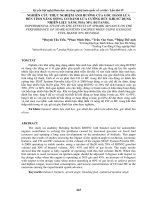
Russel et al. (1959) describe three flow patterns in
oil-water flow in a horizontal circular pipe. These are
mixed flow (M), stratified flow (S) and bubble flow (B).
They varied the oil-water volume ratio, Rv, from 0.1 to
10.0, and the superficial water velocity from 0.0354 to
1.082 m/s. Table 2.1 includes the experimental data. The
purpose was to study the effect of input ratios on the flow
patterns. Figure 2.1 shows the flow patterns at the highest
superficial water flow rate with varying input ratio. The
figure contains drawings prepared from photographs as
they were presented in their publication.
1.2.72
Table 2.1 Experimental data - Russel et al. (1959).
1.2.73
1.2.74
1.2.81
1.2.1
- 23 URN:NBN:no-1301
- 23 URN:NBN:no-1301
Fluids: water and transparent mineral oil
(paraffinic)
An experimental study of oil / water flow in horizontal pipes
Chapter 2: Liquid-liquid flow - literature review and basic models
An experimental study of oil / water flow in horizontal pipes
Chapter 2: Liquid-liquid flow - literature review and basic models
1.2.2
1.2.3
Figure 2.1 Flow patterns of mixed flow (M),
stratified flow (S) and bubble flow (B) for a fixed
water flow rate. Drawings from photographs [Russel et
al. (1959)].
1.2.82
The three flow regimes were found to appear in
both laminar and turbulent flows. At the lowest input ratio
the oil phase appears as large stretched out bubbles. With
increasing input ratio the flow approaches the stratified
pattern. By further increase of input ratio the flow
becomes mixed or dispersed.
1.2.83
- 24 URN:NBN:no-1301
- 24 URN:NBN:no-1301
An experimental study of oil / water flow in horizontal pipes
Chapter 2: Liquid-liquid flow - literature review and basic models
An experimental study of oil / water flow in horizontal pipes
Chapter 2: Liquid-liquid flow - literature review and basic models
1.2.84
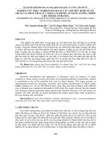
Charles et al. (1961) did a similar study of three different
oils, each mixed with water in a horizontal pipe. They varied the
superficial oil velocity from 0.015 m/s to 0.91 m/s and the
superficial water velocity from 0.03 m/s to 1.07 m/s. The input oilwater ratios ranged from 0.1 to 10.0. Table 2.2 adds up the
experimental data.
1.2.85
1.2.88
1.2.92
1.2.96
1.2. 4
1.2.99
Charles et al. (1961) observed a series of flow patterns for a
decrease of the oil flow rate at constant water flow rate. Figures 2.2
to 2.4 represent drawings from photographs of the different flow
regimes.
1.2.100
SUPERFICIAL OIL
FLOW PATTERN VELOCITY. v0,
11 P®r fiec
1.2.101
1.2.102
1.2.103
1.2.104
1.2.108
OIL
5 IN WATER CONCENTRIC
FLOW
PATTERN
WATER OROPS IN OIL
1.2.109
1.2.111
1.2.110
1.2.112
1.2.113
- 25 URN:NBN:no-1301
- 25 URN:NBN:no-1301