Ebook The finite element method (2nd edition) Part 2
Bạn đang xem bản rút gọn của tài liệu. Xem và tải ngay bản đầy đủ của tài liệu tại đây (2.1 MB, 127 trang )
5
Further topics in the finite
element method
So far, elliptic problems only have been considered, and we shall see in Section 5.1
how, with reference to Poisson problems, the variational approach is equivalent
to Galerkin’s method. Of course, for many problems of practical interest, such
variational principles may not exist, or where they do, a suitable functional may
not be known. In this chapter we shall consider procedures for a wide variety
of problems, including parabolic, hyperbolic and non-linear problems. It is not
intended to be any more than an introduction, and the ideas are presented by
way of particular problems. The reader with a specific interest in any one subject
area will find the references useful for further detail.
5.1
The variational approach
We seek a finite element solution of the problem given by eqns (3.30)–(3.32), viz.
−div(k grad u) = f (x, y)
(5.1)
in D,
with the Dirichlet boundary condition
(5.2)
u = g(s)
on C1
and the Robin boundary condition
(5.3)
k(s)
∂u
+ σ(s)u = h(s)
∂n
on C2 .
The functional for this problem is found from eqn (2.44) as
I[u] =
k
D
∂u
∂x
2
+k
∂u
∂y
2
− 2uf
(σu2 − 2uh) ds
dx dy +
C2
and the solution, u, of eqns (5.1)–(5.3) is that function, u0 , which minimizes I[u]
subject to the essential boundary condition u0 = g(s) on C1 .
We follow exactly the finite element philosophy of Section 3.4, writing
(5.4)
u
˜e (x, y)
u
˜(x, y) =
e
172
The Finite Element Method
with
u
˜e (x, y) = Ne (x, y)Ue .
(5.5)
Then
I[˜
u] =
⎧
⎨
k
D⎩
2
∂
∂x
⎧
⎨
+
σ
C2 ⎩
u
˜e
∂
∂y
+k
e
2
−2
u
˜e
e
u
˜e h
e
2
−2
u
˜e
e
u
˜e f
e
⎫
⎬
⎭
dx dy
⎫
⎬
⎭
ds.
Now, since u
˜e is zero outside element [e], the only non-zero contribution to I[˜
u]
e
from u
˜ comes from integration over the element itself. Thus
k
I[˜
u] =
[e]
e
2
+k
∂u
˜e
∂y
2
− 2˜
ue f
dx dy
2
ue h ds
σ (˜
ue ) − 2˜
+
e
I e,
=
∂u
˜e
∂x
C2
say.
e
The second term applies only if the element has a boundary coincident with C2 ;
see Fig. 3.15.
Using eqns (5.4) and (5.5),
I[˜
u] = I(U1 , U2 , . . . , Un ).
Then, using the Rayleigh–Ritz procedure to minimize I with respect to the
variational parameters Ui gives
∂I
= 0,
∂Ui
i = 1, . . . , n,
i.e.
(5.6)
e
∂I e
= 0,
∂Ui
i = 1, . . . , n.
Before developing the element matrices, it is helpful to express the equations
(5.6) as a single matrix equation.
Define
∂I e
∂I e
=
∂U
∂U1
∂I e
∂U2
...
∂I e
∂Un
T
.
173
Further topics in the finite element method
Suppose that element [e] has nodes p, q, . . . , i, . . . , s; see Fig. 3.16. Then
p
1
∂I e
=[ 0
∂U
q
∂I e
∂Up
2
0 ...
0 ...
0
∂I e
∂Uq
i
0 ...
0
∂I e
∂Ui
0
...
s
...
(5.7)
∂I e
∂Us
0
0
...
0
n T
0] ,
and the equations (5.6) become
∂I e
= 0.
∂U
e
Now,
∂I e
=
∂Ui
k
[e]
+
(5.8)
∂
∂Ui
σ
C2
∂u
˜e
∂x
2
+k
∂
∂Ui
∂u
˜e
∂y
2
−2
∂u
˜e
f
∂Ui
dx dy
∂u
˜e
∂
2
(˜
ue ) − −2
h ds.
∂Ui
∂Ui
If node i is not associated with element [e], then ∂I e /∂Ui = 0; a non-zero
contribution to ∂I e /∂Ui will occur only if node i is associated with element [e].
This is shown in eqn (5.7). For element [e], as shown in Fig. 3.16,
u
˜e (x, y) = Npe Up + Nqe Uq + . . . + Nie Ui + . . . + Nse Us =
Nje Uj .
j∈[e]
Then
∂
∂Ui
∂u
˜e
∂x
2
=2
∂u
˜e ∂
∂x ∂Ui
=2
∂u
˜e ∂
∂x ∂x
∂u
˜e
∂x
∂u
˜e
∂Ui
∂Nie
∂
(Ne Ue )
∂x
∂x
∂Nie ∂Npe
∂Nie ∂Nse
T
...
=2
[Up . . . Us ] .
∂x ∂x
∂x ∂x
=2
Similarly,
∂
∂Ui
∂u
˜e
∂y
2
=2
∂Nie ∂Npe
∂Nie ∂Nse
T
...
[Up . . . Us ] .
∂y ∂y
∂y ∂y
174
The Finite Element Method
Now,
∂u
˜e
= Nie
∂Ui
and
∂
2
T
(˜
ue ) = 2 Nie Npe . . . Nie Nse [Up . . . Us ] .
∂Ui
Thus eqn (5.8) becomes
∂Nie ∂Npe
∂Nie ∂Npe
+
∂x ∂x
∂y ∂y
[e]
⎡ ⎤
Up
e
e
e
e
∂Ni ∂Ns
∂Ni ∂Ns
⎢ .. ⎥
+
...
⎣ . ⎦ dx dy
∂x ∂x
∂y ∂y
Us
∂I e
=2
∂Ui
k
⎤
Up
⎢ .. ⎥
⎣ . ⎦ ds
⎡
−2
−2
[e]
C2e
f Nie dx dy + 2
C2e
σ Nie Npe . . . Nie Nse
Us
hNie ds,
i.e.
∂I e
=2
∂Ui
e
Uj − 2fie − 2f¯ie ,
k¯ij
e
kij
Uj + 2
j∈[e]
j∈[e]
where
(5.9)
(5.10)
(5.11)
(5.12)
e
kij
=
e
=
k¯ij
fie =
f¯ie =
k
[e]
C2e
dx dy,
σNie Nje ds,
[e]
C2e
∂Nie ∂Nje
∂Nie ∂Nje
+
∂x ∂x
∂y ∂y
f Nie dx dy,
hNie ds,
which are exactly eqns (3.40)–(3.43), developed using Galerkin’s method in
Chapter 3, and these lead as before to the matrix form given by eqns (3.45)–
(3.48). The Galerkin approach of Chapter 3 is more general, since it is applicable
in cases where a variational principle does not exist. However, the variational
175
Further topics in the finite element method
procedure ensures that the resulting stiffness matrix, reduced by enforcing
the essential boundary condition, is positive definite and hence non-singular,
provided that the differential operator L is positive definite.
Example 5.1 Consider the differential operator L given by
Lu = −div(κ grad u) dx dy.
Then
uLu dx dy = −
u div(κ grad u) dx dy
D
D
grad u · (κ grad u) dx dy −
=
D
u (κ grad u) · n ds
C
using the generalized first form of Green’s theorem (2.6). For homogeneous
Dirichlet boundary conditions, the boundary integral vanishes, and hence L is
positive definite provided that κ is positive definite. For a homogeneous Robin
boundary condition of the form
(κ grad u) · n + σu = 0,
it is also necessary that σ > 0 in order that L is positive definite (cf. Example 2.2).
Suppose that v = j wj vj , where vj is arbitrary and wj is the nodal function
associated with a node at which a Dirichlet boundary condition is not specified.
Then
−v div (κ grad v) dx dy
vLv dx dy =
D
D
grad v · (κ grad v) dx dy −
=
D
⎛
v (κ grad v) · n ds
C
⎡
⎤
⎞
∂w1 /∂x ∂w1 /∂y
⎜
⎢ ∂w2 /∂x ∂w2 /∂y ⎥ ∂w1 /∂x ∂w1 /∂y . . .
⎟
= vT ⎝
dx dy⎠v
⎣
⎦κ
/∂x
∂w
/∂y
.
.
.
∂w
.
.
2
2
D
..
..
⎛
⎡ ⎤
⎞
w1
⎜
⎢ ⎥
⎟
σ ⎣ w2 ⎦ [w1 w2 . . .] ds⎠ v,
+ vT ⎝
.
C2
..
where C2 is that part of the boundary on which a homogeneous mixed boundary
condition holds. Thus it may be seen, by comparison with Example 3.3, that
vLv dx dy = vT Kv,
D
176
The Finite Element Method
where K is the reduced overall stiffness matrix. Now, provided that κ is positive
definite and σ > 0, L is positive definite; consequently, it follows that
vT Kv > 0,
i.e. K is positive definite.
When a variational principle exists, it is always equivalent to a weighted
residual procedure. However, the converse is not true, since weighted residual
methods are applied directly to the boundary-value problem under consideration,
irrespective of whether a variational principle exists or not.
To establish this result, consider the functional
F
I[u] =
x, y, u,
D
∂u ∂u
,
,...
∂x ∂y
dx dy +
G x, y, u,
C
∂u ∂u
,
, . . . ds,
∂x ∂y
(5.13)
which is stationary when u = u0 .
Suppose that u = u0 + αv; then the stationary point occurs when
(dI/dα)|α=0 = 0; see Section 2.6. This yields an equation of the form
vLE (u) dx dy +
(5.14)
D
vBE (u) ds = 0,
C
which holds for arbitrary v; thus it follows that
(5.15)
LE (u) = 0 in D
and
(5.16)
BE (u) = 0 on C.
Equation (5.15) is the so-called Euler equation for the functional (5.13).
If eqns (5.15) and (5.16) are precisely the differential equation and boundary
conditions under consideration, then the variational principle is said to be a natural principle and it follows immediately that eqn (5.14) gives the corresponding
Galerkin method, the weighting function being the trial function v. However,
not all differential equations are Euler equations of an appropriate functional;
nevertheless, it is always possible to apply a weighted residual method.
Thus, if the Euler equations of the variational principle are identical with
the differential equations of the problem, then the Galerkin and Rayleigh–Ritz
methods yield the same system of equations. In particular, it follows from Section
2.3 that, since the variational principle associated with a linear self-adjoint
operator is a natural one, the Galerkin and Rayleigh–Ritz methods yield identical
results.
Further topics in the finite element method
177
It is worth concluding this section with a note on the terminology, since
the method described here is often associated with the name ‘Bubnov–Galerkin
method’. When piecewise weighting functions other than the nodal functions are
used, then the name ‘Petrov–Galerkin’ is associated with the procedure.
5.2
Collocation and least squares methods
Recall the weighted residual method (Section 2.3) for the solution of
Lu = f
(5.17)
in D
subject to the boundary condition
Bu = b
(5.18)
on C.
Define the residual
u) = L˜
u−f
r1 (˜
and the boundary residual
u) = B˜
u − b;
r2 (˜
then eqn (2.23) suggests the following general weighted residual equations:
(5.19)
r1 vi dx dy +
D
r2 vi ds = 0,
i = 1, . . . , n,
C2
where {vi } is a set of linearly independent weighting functions which satisfy
vi ≡ 0 on C1 , that part of C on which an essential boundary condition applies.
The trial functions u
˜ are defined in the usual piecewise sense by eqn (5.4) as
u
˜e ,
u
˜=
e
with u
˜e interpolated through element [e] in terms of the nodal values. The
equations (5.19) then yield a set of algebraic equations for these nodal values.
Notice that no restriction is placed on the operator L; it may be non-linear, in
which case the resulting set of equations is a non-linear algebraic set; see Section
5.3. Very often, the equations (5.19) are transformed by the use of an integrationby-parts formula, Green’s theorem, so that the highest-order derivative occurring
in the integrand is reduced, thus reducing the continuity requirement for the
chosen trial function.
The point collocation method requires that the boundary-value problem be
satisfied exactly at n points in the domain; this is accomplished by choosing
178
The Finite Element Method
vi (x, y) = δ(x − xi , y − yi ), the usual Dirac delta function. In practice, the collocation is usually performed at m points in the domain (m
n) and the resulting
overdetermined system is solved by the method of least squares; see Exercise 5.3.
In the subdomain collocation method, the region is divided into N subdomains (elements) Dj , and the weighting function is given by
1,
0,
vj (x, y) =
(x, y) ∈ Dj ,
otherwise.
In the least squares method, the integral
I=
D
r12 dx dy +
C
r22 ds
is minimized with respect to the nodal variables Uj , which leads to the set of
equations
∂I
= 0,
∂Ui
(5.20)
i = 1, . . . n.
In the case where the trial functions are chosen to satisfy the boundary conditions, eqn (5.20) yields
(5.21)
r1
D
∂r1
dx dy = 0,
∂Ui
i = 1, . . . n,
so that the weighting functions are given by ∂r1 /∂Ui .
Example 5.2 Consider Poisson’s equation,
−∇2 u = f.
(5.22)
The usual finite element approximation is written in the form
⎛
⎞
⎝
u
˜=
e
Nje Uj ⎠,
j∈[e]
which gives the residual
⎧
⎨
r(˜
u) = −
e
⎩
j∈[e]
∇2 Nje Uj
⎫
⎬
⎭
− f.
Thus it follows from eqn (5.21) that
⎫
⎧
⎬
⎨
∇2 Nje Uj + f ∇2 Nie dx dy = 0.
⎭
[e] ⎩
e
j∈e
Further topics in the finite element method
179
Thus element stiffness and force matrices may be obtained, given by
e
kij
=
[e]
∇2 Nje ∇2 Nie dx dy
and
fie = −
[e]
f ∇2 Nie dx dy.
Unfortunately, these integrals contain second derivatives, which means that
the trial functions must have continuous first derivatives. For this reason, the
least squares method has not been very attractive. However, if the governing
partial differential equation (5.22) is replaced by a set of first-order equations
(Lynn and Arya 1973, 1974), then the continuity requirement may be relaxed.
Let
(5.23)
ξ=
∂U
,
∂x
η=
∂U
;
∂y
then eqn (5.22) becomes
(5.24)
∂η
∂ξ
+
= −f,
∂x ∂y
and the system of equations (5.23) and (5.24) is used instead of the original
equation (5.22).
The least squares approach to minimizing the residual errors then leads
to three integral expressions. The usual finite element representation for the
unknowns U, ξ, η is then substituted into these expressions to obtain the necessary stiffness and force matrices; see Exercise 5.4.
5.3
Use of Galerkin’s method for time-dependent and
non-linear problems
When the finite element method is applied to time-dependent problems, the time
variable is usually treated in one of two ways:
(1) Time is considered as an extra dimension, and shape functions in space and
time are used. This is illustrated in Example 5.3.
(2) The nodal variables are considered as functions of time, and the space
variables are used in the finite element analysis. This leads to a system of
ordinary differential equations, which may be solved by a finite difference
or weighted residual method. This approach is illustrated in Example 5.4.
180
The Finite Element Method
A Laplace transform approach is also possible, and this is considered in
Section 5.5.
Example 5.3 Consider the diffusion equation
∇2 u =
1 ∂u
α ∂t
in D
subject to the boundary conditions
u = g(s, t)
on C1 ,
∂u
+ σ(s, t)u = h(s, t)
∂n
on C2 .
Suppose that the approximation in xyt space is given by
(5.25)
u
˜e ,
u
˜=
e
where
u
˜e = Ne (x, y, t)Ue .
(5.26)
The Galerkin procedure involves choosing the nodal functions as weighting
functions and setting the integrals of the weighted residuals to zero, just as
in Chapters 2 and 3:
T
˜+
−∇2 u
0
D
˜
1 ∂u
α ∂t
T
wi dx dy dt +
0
C2
∂u
˜
+ σu
˜ − h wi ds dt = 0,
∂n
where the nodal functions are chosen such that wi ≡ 0 on C1 . The term in the
first integral is written in this form to be consistent with the notation of Chapters
2 and 3, where, for Poisson’s equation, the differential operator was written as
−∇2 .
The first integral may be transformed using Green’s theorem for the space
variables to give
T
0
˜+
grad wi · grad u
D
˜
wi ∂ u
α ∂t
T
(σ u
˜ − h) wi ds dt.
dx dy dt +
0
C2
Then, using eqns (5.25) and (5.26), the following system of equations may be
obtained just as before:
KU = F,
(5.27)
where the element stiffness and forces are given by
T
(5.28)
e
=
kij
0
[e]
∂Nje
∂Nie ∂Nje
∂Nie ∂Nje
1
+
+ Nie
∂x ∂x
∂y ∂y
α
∂x
dx dy dt,
Further topics in the finite element method
e
=
k¯ij
(5.29)
181
T
C2e
0
σNie Nje ds dt
and
f¯ie =
(5.30)
T
0
C2e
hNie ds dt.
Notice that the stiffness matrix is no longer symmetric; this is due to the fact
that the parabolic operator −∇2 + (1/α)(∂/∂t) is not self-adjoint.
The essential boundary condition must be enforced in eqn (5.27) together
with the nodal values along the initial plane t = 0. The equations (5.27) then
give the solution at time T . This solution may then be used to step forward in
time again, and the whole time development of the solution may be obtained
in a stepping manner very similar to that used in the finite difference method
(Smith 1985).
To illustrate the procedure, consider the one-dimensional problem
∂u
∂2u
=
2
∂x
∂t
subject to the boundary conditions
u(0, t) = t,
u(2, t) = 2 + t
and the initial condition
u(x, 0) = 12 x2 .
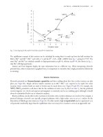
Suppose that eight triangular elements are used in the xt plane, where the time
step and the mesh size are each one unit, as shown in Fig. 5.1.
The element matrices for this problem may be obtained by using the results
and notation of Section 3.8 with y replaced by t, as follows. The shape function
matrix is
t
7
8
[6]
[8]
[5]
[7]
4
5
6
[4]
[2]
[3]
[1]
1
9
2
3
x
Fig. 5.1 Eight-element discretization for the problem of Example 5.3.
182
The Finite Element Method
Ne = [L1
L2
L3 ]
so that, using eqn (5.28),
e
kij
=
bi bj
+
4A
Li
A
cj
dx dt,
2A
i.e.
e
kij
=
ci
bi bj
+ .
4A
6
Thus, using the results of Exercise 5.6,
⎡
1
2
1
3
⎢
1
k =⎣− 23
− 16
− 12
1
2
0
4
1⎤
1
6
1⎥
,
2⎦ 2
1
4
6
4
1
2
− 61
− 12
− 61
− 61
⎡
2
⎢
k =⎣ 0
2
5
− 13
⎤
4
1⎥
,
6⎦ 2
2
5
3
.
⎡
2
3
1
3
⎢
3
k =⎣− 23
− 16
− 12
1
2
0
5
1⎤
2
2
1⎥
,
6⎦ 3
1
5
6
⎡
5
1
2
3
− 16
− 16
− 16
⎢
k =⎣ 0
4
− 12
6
− 31
⎤
5
1⎥
6⎦ 3
2
6
3
In the overall system of equations, it is only the equation for U5 that need be
set up. This equation is
K52
[K51
K53
K54
K55
K56 ] [U1
T
...
U6 ] = 0,
1
2
U5 − 13 U6 = 0.
i.e.
− 61 −
1
6
U2 + 0 −
1
6
U3 − 12 U4 +
2
3
+
1
6
+
Enforcing the essential boundary conditions
U3 = 2,
U4 = 1,
U6 = 3
and the initial condition
U2 = 12 ,
it follows that U5 = 32 .
To step forward to the next time level, t = 2, it is clear that
kn+4 = kn ,
n = 1, 2, 3, 4,
and the difference equation at node 8 thus becomes
− 13 U5 − 16 U6 − 12 U7 + 43 U8 − 13 U9 = 0.
183
Further topics in the finite element method
Enforcing the boundary conditions and the previously calculated value of U5 , it
follows that U8 = 52 .
The procedure may be repeated until the required time level is reached. The
solution at points inside an element may be found from the nodal values using
the usual linear interpolation polynomials.
The wave equation may be treated in a similar manner; see Exercise 5.8.
Example 5.4 Consider again the initial-boundary-value problem of Example 5.3
but in this case suppose that the approximation in each element is, instead of
eqn (5.26), given by
u
˜e = Ne (x, y)Ue (t),
(5.31)
where the nodal values are now assumed to be functions of time. Then, using
Galerkin’s method, the weighted residual equations become
˜+
−∇2 u
D
˜
1 ∂u
α ∂t
wi dx dy +
C2
∂u
˜
+ σu
˜ − h wi ds = 0.
∂n
Thus, substituting the approximation given by eqns (5.25) and (5.31) and using
Green’s theorem, these become
[e] j∈[e]
e
+
grad wi · grad Nje Uj dx dy +
e
wi Nje Uj ds −
σ
e
C2e
e
j∈[e]
C2e
[e]
1
α
wi Nje
j∈[e]
dUj
dx dy
dt
hwi ds = 0.
This system is seen to be a set of ordinary differential equations of the form
(5.32)
˙ + KU = F,
CU
where K and F are the usual overall stiffness and force matrices and the matrix C
is often referred to as the overall conductivity matrix, since the diffusion equation
T
models heat conduction. Since ce = [e] Ne Ne dx dy (cf. the mass matrix me
in Exercise 3.24), it is clear that C is symmetric. Some authors, by virtue of the
structural origins of the finite element method, refer to C as the damping matrix.
A finite difference approach to the solution of this system of equations is to
take a sequence of time steps of length Δt from time level j to j + 1.
Using a forward difference scheme given by
˙ ≈ (Uj+1 − Uj )/Δt,
U
eqn (5.32) becomes approximated by
(5.33)
1
1
CUj+1 + K −
C Uj = Fj .
Δt
Δt
184
The Finite Element Method
Knowing the initial value U0 , the time-stepping procedure can start and the
solution be developed by marching forward to the next time level, etc.
To illustrate the method, return to the one-dimensional problem of Example 5.3. In this case, two elements are used in space and these are taken to be
simple linear elements of the type discussed in Section 3.5. Thus, using the results
of that section,
⎡
⎤
1 −1 0
K = ⎣ −1 2 −1 ⎦.
0 −1 1
The element conductivity matrix is given by
ce =
1
2 (1
1
2 (1
1
−1
− ξ)
h
1
(1 + ξ)
dξ,
2
2
1
(1 − ξ)
2
+ ξ)
where h is the length of the element as in Section 3.5. For the problem under
consideration, h = 1, and thus
ce =
1
6
2 1
1 2
.
The overall conductivity matrix is, therefore,
⎡
⎤
2 1 0
1
C = ⎣ 1 4 1 ⎦.
6
0 1 2
If the three nodes are situated at x = 0, 1, 2 and if Δt = 1, it follows that, since
Fj = 0, eqn (5.33) yields the set of equations
⎡
⎡
⎤
⎤
⎡ ⎤
⎤⎡
⎤⎡
2 1 0
4 −7
0
0
U1
U1
1⎣
1
+ ⎣ −7
1 4 1 ⎦⎣ U2 ⎦
8 −7 ⎦⎣ U2 ⎦ = ⎣ 0 ⎦.
6
6
U3 j+1
U3 j
0 1 2
0 −7
4
0
Initially, U0 = 0
1
2
2
T
and the boundary conditions give
U1j = j Δt = j,
U3j = 2 + j Δt = 2 + j;
thus, at time level 1,
1 + 4U21 + 3 + 8 ×
1
2
− 7 × 2 = 0,
which gives U21 = 32 . Similarly, at time level 2,
2 + 4U22 + 4 − 7 + 8 ×
which gives U22 = 52 .
3
2
− 7 × 3 = 0,
Further topics in the finite element method
185
Other difference schemes could of course be used instead of forward differences in eqn (5.32); this approach actually replaces Uj by a suitably truncated
Taylor series. If, instead, a weighted residual approach in time is used, a more
general recurrence relation can be set up (Zienkiewicz and Taylor 2000a).
Suppose that between time levels j and j + 1, Ui (t) is interpolated by
Ui (t) = [1 − τ
Uij+1 ]T ,
τ ][Uij
where t = (j + τ ) Δt with 0 ≤ τ ≤ 1; see Fig. 5.2.
Then
˙ i (t) = 1 [−1 1] [Uij
U
Δt
T
Uij+1 ] .
Using the same interpolation for F, eqn (5.32) may be written as
(5.34)
1
C[Uj+1 − Uj ] + K [τ Uj+1 + (1 − τ )Uj ] = τ Fj+1 + (1 − τ )Fj .
Δt
Thus, multiplying by a weighting function v, and integrating with respect to τ
from 0 to 1, eqn (5.34) becomes
(5.35)
1
1
C + rK Uj+1 + − C + (1 − r)K Uj = rFj+1 + (1 − r)Fj ,
Δt
Δt
1
1
where r = 0 τ v dτ / 0 v dτ .
Equation (5.35) is a recurrence formula for the nodal values at two time
levels. By choosing different values for the parameter r, well-known difference
formulae are recovered; for example, r = 0, 12 and 1 give the forward, Crank–
Nicolson and backward difference formulae, respectively. Recurrence formulae
for nodal values at three time levels may be obtained by integrating over two
consecutive time intervals in the weighted residual equation; see Exercise 5.10.
Finally, the procedure may also be adopted to solve second-order equations of
the form
¨ + CU
˙ + KU = F,
MU
1- τ
τ=0
j
τ
τ=1
j+1
Fig. 5.2 Node i at times levels j and j + 1, showing the linear interpolation polynomials
in time.
186
The Finite Element Method
which arise in the finite element solution of propagation problems; see Exercises 5.11 and 5.12.
This discussion of time-dependent problems has been necessarily brief; for
further details, there are two excellent chapters in the book by Zienkiewicz et al.
(2005).
As well as time-dependent problems, the weighted residual method may
also be used to tackle non-linear problems as illustrated in Example 5.5. In these
cases, however, the resulting system of algebraic equations is no longer linear,
and iterative techniques are usually necessary for their solution.
Example 5.5 Consider the equation
−div(k grad u) = f
in D
subject to the boundary conditions
k
u=g
on C1 ,
∂u
+ σu = h
∂n
on C2 .
In this case suppose that k, f , σ and h all depend on u as well as on position.
The weighted residual method may be applied in the usual manner, and if the
weighting functions are the nodal functions, then the element matrices become
(5.36)
ke (Ue ) =
[e]
¯e (Ue ) =
k
kαT α dx dy,
T
σNe Ne ds,
C2e
T
f e (Ue ) =
f Ne dx dt,
[e]
¯
f e (Ue ) =
hNe ds
C2e
(cf. eqns (3.45)–(3.48)). However, in this case the unknown u occurs under the
integral sign, so that the matrices themselves are functions of the nodal variables.
The overall system is assembled in the usual way to yield a set of equations of
the form
(5.37)
K(U)U = F(U).
To illustrate the idea, consider the one-dimensional problem
−(uu ) + 1 = 0,
u(0) = 1,
0 < x < 1,
u(1) = 0.
187
Further topics in the finite element method
Suppose that two linear elements of the type discussed in Section 3.5 are used.
Then
ke (u) =
1
u
−1
=
−1/h
[−1/h
1/h
1
1
1 −1
2h −1 1
−1
1/h]
1
2 (1
− ξ)
h
dξ
2
1
2 (1
+ ξ) [uA
uB ]T dξ,
where the notation of Fig. 3.7 is used. Thus
UA + UB
2h
ke (Ue ) =
1 −1
.
−1 1
With the two-element idealization of Fig. 3.6, it follows that, with h = 12 ,
⎡
K(U) =⎣
1
U1 + U2
2
−U1 − U2
U1 + 2U2 + U3
sym
3
⎤
0
1
−U2 − U3 ⎦ 2 .
U2 + U3
4
Since f ≡ −1, it follows from Example 3.1 that
F = − 14
1
2
3
1
2
1 ] .
T
The only node without an essential boundary condition is node 2; thus assembling
only the equation for node 2 yields
(−U1 − U2 )U1 + (U1 + 2U2 + U3 )U2 + (−U2 − U3 )U3 = − 12 .
Since U1 = 1 and U3 = 0, it follows that
U22 =
1
4
and hence that
U2 = ± 21 .
The non-linear algebraic system has led to two possible solutions, and some
knowledge of the behaviour of the solution to the original boundary-value problem is necessary in order that the correct value may be chosen. In this case, it may
be shown that the solution U2 = − 12 is not possible, since this would imply that
there is a point xp ∈ (0, 1) with the properties U (xp ) < 0, U (xp ) = 0, U (xp ) > 0.
These properties are not consistent with the original differential equation. Thus
the solution required is U2 = 12 . This situation is typical of non-linear problems,
where it is extremely useful to have some intuitive idea of the behaviour of the
solution or the physics of the problem.
188
The Finite Element Method
The problem considered here is of course very simple, leading to a non-linear
algebraic equation whose solution is amenable to hand calculation. In practice,
this does not occur, and numerical methods of solution are necessary. In general,
either an iterative or incremental approach is adopted. Write eqn (5.37) as
(5.38)
A(U) ≡ K(U)U − F(U) = 0;
then the Newton–Raphson method gives the following iterative scheme:
(5.39)
Un+1 = Un − G−1
n A(Un ),
where
Gn = [∂Ai /∂Uj ]n .
The solution proceeds by assuming an initial value U0 and then iterating with
eqn (5.39) until sufficient accuracy is obtained.
Unfortunately, an iterative approach will not always converge; however,
incremental methods will always converge. Suppose that, for some given value
F0 of F, eqn (5.38) has the known solution U0 ; then the solution proceeds by
adding small increments to F and finding the corresponding increments in U.
Write eqn (5.37) as
H(U) − λF∗ = 0,
where
H(U) = K(U)U
and λF∗ = F(U).
Then, differentiating with respect to λ,
J
dU
− F∗ = 0,
dλ
where
(5.40)
J = [∂Hi /∂Uj ];
thus
(5.41)
dU
= J−1 F∗ .
dλ
Using a forward difference to approximate the derivative in eqn (5.41),
∗
(Un+1 − Un )/Δλn = J−1
n F ,
where
Jn = J(Un ).
Further topics in the finite element method
189
Thus the incremental scheme is
Un+1 = Un + J−1
n ΔFn ,
(5.42)
where ΔFn = Δλn F∗ is the nth increment in F. Simple problems illustrating
the use of these methods may be found in Exercises 5.13–5.16.
It has been the intention of this section to illustrate the way in which the
Galerkin finite element approach may be used to solve time-dependent and nonlinear problems. Only simple examples have been introduced, the general area of
such problems being well beyond the scope of this text. Much research has been
conducted in these areas, and the interested reader is recommended to consult
the books by Zienkiewicz and Taylor (2000a,b) for references to specific subject
areas such as plasticity, electromagnetic theory and viscous flow.
5.4
Time-dependent problems using variational principles
which are not extremal
In Section 2.9, variational principles for time-dependent problems were introduced. In this section, they are used to develop finite element solutions to
the wave and heat equations. Some authors feel that a direct approach to the
problem at hand is better than using such variational problems, either because
the solutions do not yield extrema for the functionals involved (Finlayson and
Scriven 1967) or because a weighted residual approach is more general, since
there is always a Galerkin method equivalent to a given variational principle
(Zienkiewicz and Taylor 2000a). However, it is a possible approach when such
principles exist and a suitable functional is known, and it gives users another
weapon in their finite element armoury.
Example 5.6 (Noble 1973). Consider the wave equation
(5.43)
1 ∂2u
∂2u
= 2 2,
2
∂x
c ∂t
0 < x < 1,
t > 0,
subject to the boundary conditions
(5.44)
u(0, t) = u(l, t) = 0
and the initial conditions
(5.45)
(5.46)
u(x, 0) = f (x),
∂u
(x, 0) = g(x).
∂t
From Section 2.9, it follows that the functional (2.75) is stationary at the solution
of eqn (5.43) subject to eqn (5.44) and (5.45) and a condition at time Δt of
the form
190
The Finite Element Method
u(x, Δt) = h(x),
which replaces eqn (5.46).
Of course, h(x) is not known; however, it is treated as if it is known and
then, at the end of the analysis, eqn (5.46) is used to eliminate this unknown
function.
Suppose that l = 1 and that [0, 1] is divided into E elements. Consider the
usual finite element approximation
u
˜e ,
u
˜=
e
where
u
˜e = Ne (x)Ue (t).
Then, using the functional (2.75),
Δt
c2
I=
e
0
Ue
1
T
0
αT α dx Ue dt −
Δt
1
˙ eT
U
0
T
˙ e dt ,
Ne Ne dx U
0
(5.47)
where, as usual, α= dNe /dx.
For the linear element of length h discussed in Section 3.5, the x integrations
are easily performed to yield the two matrices
1
1 −1
h −1 1
and
h 21
.
6 12
These are just the usual element stiffness and mass or conductivity matrices, see
Exercise 3.24 and Example 5.4.
To satisfy the essential conditions at node i at times t = 0 and t = Δt, set
U (0) = fi and U (Δt) = hi . Now U (t) may be interpolated between t = 0 and
t = Δt as a quadratic function
(5.48)
Ui (t) = (1 − τ 2 )fi + τ 2 hi + ai Δt(τ − τ 2 ),
where τ = t/Δt and ai = U˙ i (0). Also,
2
(hi − fi ) + ai (1 − 2τ ).
U˙ i (t) =
Δt
At this stage ai is treated as unknown, so that substitution of eqn (5.48) into
eqn (5.47) gives I = I(a1 , . . . , an ).
Stationary values of I occur when ∂I/∂ai = 0, i = 1, . . . , n. If I = e I e ,
then
191
Further topics in the finite element method
∂I e
=2
∂ai
1
0
=h −
+
c2
h
(Ui − Ui−1 ) Δt(τ − τ 2 ) − (2U˙ i + U˙ i−1 )(1 − 2τ ) Δt dτ
h
6
1 7μ2
+
9
30
1 μ2
−
9 30
fi−1 +
μ2
2
+
10 9
hi−1 +
1 μ2
+
9 15
+ Δt −
7μ2
2
−
30
9
fi
hi
μ2
2
−
15 9
ai−1 +
,
ai
where μ = c Δt/h.
A similiar result may be obtained when element [e] contains nodes i and
i + 1. Assembling the complete equations e ∂I e /∂ai = 0 yields
(5.49)
−
1 7μ2
+
9
30
+
1 μ2
−
9 30
+ Δt −
fi−1 + 2
hi−1 + 2
1 μ2
+
9 15
7μ2
2
−
30
9
μ2
2
+
10 9
fi −
hi +
μ2
2
−
15 9
ai−1 + 2
1 7μ2
+
9
30
1 μ2
−
9 30
ai −
fi+1
hi+1
1 μ2
+
9 15
ai+1 = 0.
This system of equations allows hi to be found, since fi and ai are known.
To illustrate the technique, suppose that c = 1 and
f (x) =
x,
0 ≤ x ≤ 12 ,
1 − x,
1
2
≤ x ≤ 1,
g(x) = 0.
Take four equal elements along the x-axis and suppose that Δt = 0.1, so that
μ = 0.4. Then the difference equation for the unknown function h is
0.1058hi−1 + 0.4764hi + 0.01058hi+1 = 0.1484(fi−1 + fi+1 ) + 0.3698fi
+ 0.01218(ai−1 + ai+1 ) + 0.04231ai ,
(5.50)
i = 2, 3, 4.
Now the boundary conditions give
f1 = f5 = h1 = h5 = 0,
and the initial conditions give f2 = 0.25, f3 = 0.5, f4 = 0.25, ai = 0. Substituting these values in eqn (5.49) and solving the resulting equation yields
h2 = h4 = 0.254,
h3 = 0.431
192
The Finite Element Method
and
(5.51)
U˙ (0.1) = 20(hi − fi ) − ai = bi ,
say.
However, hi − fi is the difference between two nearly equal numbers and, to
avoid inaccuracies, hi is eliminated between eqns (5.50) and (5.51) to give
0.00529bi−1 + 0.02382bi + 0.00529bi+1 = 0.0426(fi−1 + fi+1 ) − 0.1066fi
+ 0.00689(ai−1 + ai+1 ) + 0.01849ai .
Using the initial conditions and boundary conditions previously stated,
together with b1 = b5 = 0, three equations may be obtained, to yield the solutions
b2 = b4 = 0.082,
b3 = −1.380.
The procedure may now be repeated using the calculated values at t = Δt to step
forward in time once again. Thus a step-by-step method has been developed, and
the solution at any time t may be obtained by taking a sufficiently large number
of steps.
The use of a time-dependent variational principle in the finite element
solution of the heat equation is considered in Exercise 5.18. The principle involved
is in fact related to another principle, developed by Gurtin (1964) using the
Laplace transform. This will not be discussed here; instead, a procedure using
the Laplace transform directly will be considered in the next section.
5.5
The Laplace transform
Until recently, this approach has not been particularly popular. However, the
use of Stehfest’s numerical inversion method (Stehfest 1970a,b) has developed
a new interest in the Laplace transform associated with finite element methods
(Moridis and Reddell 1991). A very good introduction to the use of the Laplace
transform for diffusion problems has been given, in the context of boundary
integral methods, by Zhu (1999).
Example 5.7 Consider the diffusion equation
(5.52)
1 ∂u
∂2u
,
=
2
∂x
α ∂t
0 < x < l,
t > 0,
subject to the boundary conditions
u(0, t) = g1 (t),
u(l, t) = g2 (t)
and the initial condition
u(x, 0) = f (x).
193
Further topics in the finite element method
If
∞
e−λt u(x, t) dt
u
¯(x; λ) =
0
is the Laplace transform in time of u(x, t), then, using the Laplace transform,
eqn (5.52) becomes the ordinary differential equation
d2 u
¯
1
u − f (x)),
= (λ¯
2
dx
α
which we write as
−
d2 u
1
¯
λ
¯ = f (x).
+ u
2
dx
α
α
The boundary conditions transform to
u
¯(0; λ) = g¯1 (λ),
u
¯(l; λ) = g¯2 (λ).
The effect of the Laplace transform is to remove the time dependence and the
initial condition, leaving a two-point boundary-value problem to be solved. It
is not difficult to see that for two-dimensional diffusion problems, the parabolic
nature is removed, leaving an elliptic boundary-value problem.
To illustrate the approach, consider again the one-dimensional problem
presented in Example 5.3. Then, using the Laplace transform, the equation and
boundary conditions become
u = 12 x2 ,
−¯
u + λ¯
u
¯(0; λ) =
1
,
λ2
1
2
+ .
λ λ2
u
¯(2; λ) =
Using two equal linear elements, the overall matrices may be obtained from
Example 5.4 and Exercise 3.24 as
⎡
⎤
⎡
⎤
2 1 0
1 −1 0
K = ⎣ −1 2 −1 ⎦ , C = 16 ⎣ 1 4 1 ⎦ .
0 1 2
0 −1 1
The element force vectors are
1
f1 =
0
2
f2 =
1
Thus, F =
conditions
1
24 [1
14
1
24
1 2
2x
[1 − x
x] dx =
1 2
2x
[2 − x
x − 1] dx =
T
T
T
[1 3] ,
1
24
[11
T
17] .
17]T . Now, after enforcing the essential boundary
194
The Finite Element Method
¯3 = 2 + 1 ,
U
λ λ2
¯1 = 1 ,
U
λ2
¯2 :
there is just one equation for U
−
1
¯2 −
+ 2U
λ2
2
1
+ 2
λ λ
+
1
¯2 + 2 + 1
+ 4U
2
λ
λ λ2
λ
6
=
7
,
12
which yields
1
¯2 = 1 + 1 −
U
.
2
λ λ
8(3 + λ)
Inverting then gives
(5.53)
U2 (t) =
1
2
+ t − 18 e−3t .
A drawback in this approach is the fact that the transform variable λ is
carried through the analysis. This causes no difficulty in the simple hand calculation given, but it is not at all convenient for a numerical procedure. In practice,
the equations could be solved for discrete set of values λ1 , λ2 , . . . , λM and the
resulting transforms inverted numerically. Before we consider this approach, we
shall illustrate the use of the convolution theorem.
Example 5.8 Consider the wave equation with boundary and initial conditions
as in Example 5.6. Then, taking the Laplace transform,
c2
d2 u
¯
= λ2 u
¯ − λf (x) − g(x),
dx2
i.e.
−c2 d2 u
1
¯
1
+u
¯ = f (x) + 2 g(x).
λ2 dx2
λ
λ
This equation may be inverted as
(5.54)
−c2
d2
(t ∗ u) + u = f (x) + tg(x),
dx2
where the convolution integral is given by
t
F (t) ∗ G(t) =
0
F (t − u)G(u) du.
One way of solving the integro-differential equation (5.54) is to use an
appropriate functional (Martin and Carey 1973). An alternative procedure, which
will be used here, is to assume a time variation for u in the interval 0 ≤ t ≤ Δt,
evaluate the convolution integral and use a finite element analysis to solve the
resulting two-point boundary-value problem.
195
Further topics in the finite element method
Suppose that the approximation is
u
˜e ,
u
˜=
e
where
u
˜e =
Nie (x)Ui (t).
i∈[e]
The time variation for Ui is taken to be given by
Ui (t) = [(1 − τ 2 )
τ2
Δt(τ − τ 2 )][Ui (0)
Ui (Δt)
U˙ i (0)]T
with τ = t/Δt. Then
t∗u
˜=
Nie (x)t ∗ Ui
e i∈[e]
Nie (x)Δt2
=
5
12 Ui (0)
+
1
12 Ui (Δt)
+
17
60 Δt
U˙ i (0)
at t = Δt,
e i∈[e]
Nie (x)
=
e i∈[e]
Δt2
(25fi + 5hi + 7Δt ai )
60
using the notation of eqn (5.48). Thus, using the two-node linear element in the
space variable x (see Fig. 3.7), it follows that the element matrices are
c2
h
ke =
1 −1
,
−1 1
mc =
h 21
6 12
and
fe =
1
−1
= me
1 1−ξ
h
[f (x) + Δt g(x)] dξ
2 1+ξ
2
fi−1 + Δt ai−1
.
fi + Δt ai
Thus the overall system is assembled in the usual way to give the following
difference equation at node i:
−
(5.55) +
1 5μ2
+
6
12
1 μ2
−
6 12
+ Δt −
fi−1 +
5μ2
2
−
6
3
1 5μ2
+
6
12
fi −
hi−1 +
2 μ2
+
3
6
hi +
1 17μ2
+
6
60
ai−1 +
17μ2
2
−
30
3
where μ = c Δt/h.
1 μ2
−
6 12
ai −
fi+1
hi+1
1 17μ2
+
6
60
ai+1 = 0,