Ebook Chemical engineering Part 2
Bạn đang xem bản rút gọn của tài liệu. Xem và tải ngay bản đầy đủ của tài liệu tại đây (1.73 MB, 208 trang )
SECTION 9
Heat Transfer
PROBLEM 9.1
Calculate the time taken for the distant face of a brick wall, of thermal diffusivity, DH D
0.0042 cm2 /s and thickness l D 0.45 m, initially at 290 K, to rise to 470 K if the near
face is suddenly raised to a temperature of  0 D 870 K and maintained at that temperature.
Assume that all the heat flow is perpendicular to the faces of the wall and that the distant
face is perfectly insulated.
Solution
The temperature at any distance x from the near face at time t is given by:
ND1
ÂD
p
1 N Â 0 ferfc[ 2lN C x / 2 DH t ] C erfc[2 N C 1 l
p
x/ 2 DH t ]g
ND0
(equation 9.37)
and the temperature at the distant face is:
ND1
ÂD
p
1 N Â 0 f2 erfc[ 2N C 1 l]/ 2 DH t g
ND0
Choosing the temperature scale such that the initial temperature is everywhere zero,
Â/2Â 0 D 470
290 /2 870 290 D 0.155
p
DH D 0.0042 cm2 /s or 4.2 ð 10 7 m2 /s, DH D 6.481 ð 104
and l D 0.45 m
ND1
1 erfc 347 2N C 1 /t0.5
Thus: 0.155 D
ND0
D erfc 347t
0.5
erfc 1042t
0.5
C erfc 1736t
0.5
Considering the first term only, 347t 0.5 D 1.0 and t D 1.204 ð 105 s
The second and higher terms are negligible compared with the first term at this value
of t and hence: t D 0.120 Ms (33.5 h)
125
126
CHEMICAL ENGINEERING VOLUME 1 SOLUTIONS
PROBLEM 9.2
Calculate the time for the distant face to reach 470 K under the same conditions as
Problem 9.1, except that the distant face is not perfectly lagged but a very large thickness
of material of the same thermal properties as the brickwork is stacked against it.
Solution
This problem involves the conduction of heat in an infinite medium where it is required
to determine the time at which a point 0.45 m from the heated face reaches 470 K.
The boundary conditions are therefore:
 D 0,
 D Â0 , t > 0
t D 0;
 D 870
290 D 580 deg K,
 D 0,
x D 1,
 D 0,
x D 0,
2
x D 0, t > 0
t>0
tD0
∂ Â
∂2 Â
∂ Â
C
C
∂x 2
∂y 2
∂z2
∂Â
D DH
∂t
D DH
for all values of x
∂2 Â
∂x 2
2
(for unidirectional heat transfer)
(equation 9.29)
1
 D ÂN D
The Laplace transform of:
Âe
pt
dt
(i)
0
d2 ÂN
p N ÂN tD0
D
Â
2
dx
DH
DH
p
p
Integrating equation (ii): ÂN D B1 ex p/DH C B2 e x p/DH C ÂtD0 /p
p
p
p
p
dÂN
D B1 p/DH ex p/DH
B2 p/DH e x p/DH
and:
dx
and hence:
1
ÂN t>0 D
In this case,
xD0
∂Â
∂t
and:
Â0 e
pt
1
∂Â
∂t
dt D Â 0 /p
0
D
0
t>0
xD0
e
pt
dt D 0
Substituting the boundary conditions in equations (iii) and (iv):
ÂN t>0 D Â 0t>0 /p D B1 C B2 C ÂtD0 /p or
xD0
and:
∴
B1 C B2 D Â 0t>0 /p
xD0
∂ÂN
∂t
B1
xD0
D 0 D B1
p
p
p/DH e1
B2
p
p/DH e
t>0
xD0
p/DH D 0 and B1 D 0,
B2 D Â 0t>0 /p
xD0
1
(ii)
(iii)
(iv)
127
HEAT TRANSFER
ÂN D B2 e
From (iii),
p
x
p/DH
The Laplace transform of p 1 e
p
k p
D Â0 p 1e
xD0
When x D 0.45 m, Â D 470
10 7 m2 /s,
p
where k D x/ DH
p
D erfc k/2 t (from Volume 1, Appendix).
 D  0t>0 erfc
and:
p
k p
x
p
2 DH t
(v)
290 D 180 deg K, and hence in (v), with DH D 4.2 ð
p
180/580 D erfcf[0.45/ 6.481 ð 10 4 ][1/ 2 t ]g D 0.31
p
0.45/6.481 ð 10 4 /2 t D 0.73
∴
t D 2.26 ð 105 s or
and:
0.226 Ms 62.8 h
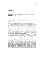
As an alternative method of solution, Schmidt’s method is used with the construction shown in Fig. 9a. In this case x D 0.1 m and it is seen that at x D 0.45 m, the
temperature is 470 K after a time 20 t.
In equation 9.43: t D 0.1 2 / 2 ð 4.2 ð 10 7 D 1.191 ð 104 s
and hence the required time, t D 20 ð 1.191 ð 104 D 2.38 ð 105 s D 0.238 Ms 66.1 h
The difference here is due to inaccuracies resulting from the coarse increments of x.
900
870
800
9
7
Temperature (K)
16
700
19
17
14
12
10
5
8
3
6
15
600
13
11
20
18
16
500
4
1
9
7
14
470
19
2
12
17
10
20
18
400
16
19
14
17
12
5
15
13
8
11
6
3
9
15
13
300
290
1.5
10
1.4
1.3
1.2
1.1
9
10
11
1.0
0.9
0.8
0.7
11
9
7
0.6
10
7
4
8
5
6
0.5
0.4
0.3
0.2
0.1
0
Distance from hot face (m)
Figure 9a.
PROBLEM 9.3
Benzene vapour, at atmospheric pressure, condenses on a plane surface 2 m long and
1 m wide maintained at 300 K and inclined at an angle of 45° to the horizontal. Plot the
thickness of the condensate film and the point heat transfer coefficient against distance
from the top of the surface.
128
CHEMICAL ENGINEERING VOLUME 1 SOLUTIONS
Solution
At 101.3 kN/m2 , benzene condenses at Ts D 353 K. With a wall temperature of Tw D
300 K, the film properties at a mean temperature of 327 K are:
D 4.3 ð 10
4
N s/m2 ,
D 860 kg/m3 , k D 0.151 W/m K and
D 423 kJ/kg D 4.23 ð 105 J/kg
Thus:
s D f[4 k Ts
Tw x]/ g sin
D f[4 ð 4.3 ð 10
4
2
ð 0.151 353
g0.25
(equation 9.168)
300 x]/ 9.81 sin 45° ð 4.23 ð 105 ð 8602 g0.25
D 2.82 ð 10 4 x 0.25 m
Similarly:
hDf
2
k 3 /[4
g sin
Ts
Tw x]g0.25
D f 8602 ð 9.81 sin 45° ð 4.23 ð 105 ð 0.1513 /[4 ð 4.3 ð 10
D 535x
0.25
(equation 9.169)
4
353
300 x]g0.25
W/m2 K
Values of x between 0 and 2.0 m in increments of 0.20 m are now substituted in these
equations with the following results, which are plotted in Fig. 9b.
Thickness of film (s mm)
750
700
0.25
650
0.20
600
0.15
550
0.10
500
0.05
450
0
0.2 0.4 0.6 0.8 1.0 1.2 1.4 1.6
Distance from top of surface (x m)
Figure 9b.
Heat transfer coefficient (h W/m2 K)
800
129
HEAT TRANSFER
x
(m)
x 0.25
x
0.25
0
0.1
0.2
0.4
0.6
0.8
1.0
1.2
1.4
1.6
1.8
2.0
0
0.562
0.669
0.795
0.880
0.946
1.000
1.047
1.088
1.125
1.158
1.189
1
1.778
1.495
1.258
1.136
1.057
1.000
0.956
0.919
0.889
0.863
0.841
s
(m)
0
1.58 ð 10
1.89 ð 10
2.24 ð 10
2.48 ð 10
2.67 ð 10
2.82 ð 10
2.95 ð 10
3.07 ð 10
3.17 ð 10
3.27 ð 10
3.35 ð 10
h
W/m2 K
1
951
800
673
608
566
535
512
492
476
462
450
4
4
4
4
4
4
4
4
4
4
4
PROBLEM 9.4
It is desired to warm 0.9 kg/s of air from 283 to 366 K by passing it through the pipes
of a bank consisting of 20 rows with 20 pipes in each row. The arrangement is in-line
with centre to centre spacing, in both directions, equal to twice the pipe diameter. Flue
gas, entering at 700 K and leaving at 366 K, with a free flow mass velocity of 10 kg/m2 s,
is passed across the outside of the pipes. Neglecting gas radiation, how long should the
pipes be?
For simplicity, outer and inner pipe diameters may be taken as 12 mm. Values of k
and , which may be used for both air and flue gases, are given below. The specific heat
capacity of air and flue gases is 1.0 kJ/kg K.
Temperature
(K)
Thermal conductivity
k(W/m K)
250
500
800
0.022
0.044
0.055
Viscosity
(mN s/m2 )
0.0165
0.0276
0.0367
Solution
Heat load, Q D 0.9 ð 1.0 366
Temperature driving force, Â1 D
Â2 D
and in equation 9.9, Âm D 334
283 D 74.7 kW
700 366 D 334 deg K,
366 283 D 83 deg K
83 / ln 334/83 D 180 deg K
130
CHEMICAL ENGINEERING VOLUME 1 SOLUTIONS
Film coefficients
Inside:
0.8
hi di /k D 0.023 dG0 /
Cp /k
di D 12 mm or 1.2 ð 10
2
0.4
(equation 9.61)
m.
The mean air temperature D 0.5 366 C 283 D 325 K and k D 0.029 W/m K.
Cross-sectional area of one tube D
4
Area for flow D 20 ð 20 1.131 ð 10
D 4.52 ð 10
Thus, mass velocity G D 0.9/ 4.52 ð 10
At 325 K,
2 2
/4 1.2 ð 10
2
D 1.131 ð 10
2
4
m2
m2 .
D 19.9 kg/m2 s.
D 0.0198 mN s/m2 or 1.98 ð 10
N s/m2
5
Cp D 1.0 ð 103 J/kg K
Thus: hi ð 1.2 ð 10
2
2
/ 2.9 ð 10
D 0.023 1.2 ð 10
2
ð 19.9/1.98 ð 10
ð 1.0 ð 103 ð 1.98 ð 10 5 /0.029
0.4138hi D 0.023 1.206 ð 104
0.8
0.683
5 0.8
0.4
and hi D 87.85 W/m2 K
0.4
Outside:
0.6
max
ho do /k D 0.33Ch do G0 /
do D 12.0 mm
or
0.3
Cp /k
1.2 ð 10
2
(equation 9.90)
m
2
0
G D 10 kg/m s for free flow
G0max D YG0 / Y
do
where Y, the distance between tube centres D 2do D 2.4 ð 10
2
m.
∴
2
D 20 kg/m2 s
G0max D 2.4 ð 10
2
ð 10.0 / 2.4 ð 10
2
1.2 ð 10
At a mean flue gas temperature of 0.5 700 C 366 D 533 K,
D 0.0286 mN s/m2 or 2.86 ð 10
103 J/kg K
∴
Remax D 1.2 ð 10
2
5
N s/m2 , k D 0.045 W/m K and Cp D 1.0 ð
ð 20.0 / 2.86 ð 10
5
D 8.39 ð 103
From Table 9.3, when Remax D 8.39 ð 103 , X D 2do , and Y D 2do , Ch D 0.95.
Thus:
ho ð 1.2 ð 10
2
/ 4.5 ð 10
2
D 0.33 ð 0.95 8.39 ð 103
ð 1.0 ð 103 ð 2.86 ð 10
or:
0.267ho D 0.314 8.39 ð 103
0.6
0.836
0.3
0.6
5
and ho D 232 W/m2 K
Overall:
Ignoring wall and scale resistances, then:
1/U D 1/ho C 1/hi D 0.0114 C 0.0043 D 0.0157
and:
/0.045
U D 63.7 W/m2 K
0.3
131
HEAT TRANSFER
Area required
In equation 9.1, A D Q/UÂm D 74.7 ð 103 / 63.7 ð 180 D 6.52 m2 .
Area/unit length of tube D
/4 12 ð 10
2
D 9.43 ð 10
total length of tubing required D 6.52/ 9.43 ð 10
3
3
m2 /m and hence:
D 6.92 ð 102 m.
The length of each tube is therefore D 6.92 ð 102 / 20 ð 20 D 1.73 m
PROBLEM 9.5
A cooling coil, consisting of a single length of tubing through which water is circulated, is
provided in a reaction vessel, the contents of which are kept uniformly at 360 K by means
of a stirrer. The inlet and outlet temperatures of the cooling water are 280 K and 320 K
respectively. What would be the outlet water temperature if the length of the cooling coil
were increased by 5 times? Assume the overall heat transfer coefficient to be constant
over the length of the tube and independent of the water temperature.
Solution
(equation 9.1)
Q D UATm
where Tm is the logarithmic mean temperature difference. For the initial conditions:
Q1 D m1 ð 4.18 320
280 D U1 A1 [ 360
[ln 360
or:
and:
280
280 / 360
167.2m1 D U1 A1 80
360
320 ]/
320 ]
40 / ln 80/40 D 57.7U1 A1
m1 /U1 A1 D 0.345
In the second case, m2 D m1 , U2 D U1 , and A2 D 5A1 .
∴
Q2 D m1 ð 4.18 T
280 D 5U1 A1 [ 360
ln 360
or:
4.18 m1 /U1 A1 T
280 /5 D 80
280
280 / 360
360
T ]/
T
360 C T /[ln[80/360
T]
Substituting for m1 /U1 A1 ,
0.289 T
or:
ln[80/ 360
280 D T
280 /[ln 80/ 360
T ] D 3.467 and
T]
T D 357.5 K
PROBLEM 9.6
In an oil cooler, 216 kg/h of hot oil enters a thin metal pipe of diameter 25 mm. An
equal mass of cooling water flows through the annular space between the pipe and a
132
CHEMICAL ENGINEERING VOLUME 1 SOLUTIONS
larger concentric pipe; the oil and water moving in opposite directions. The oil enters at
420 K and is to be cooled to 320 K. If the water enters at 290 K, what length of pipe
will be required? Take coefficients of 1.6 kW/m2 K on the oil side and 3.6 kW/m2 K on
the water side and 2.0 kJ/kg K for the specific heat of the oil.
Solution
Heat load
Mass flow of oil D 6.0 ð 10
2
kg/s.
2
and hence, Q D 6.0 ð 10 ð 2.0 420 320 D 12 kW
Thus the water outlet temperature is given by:
12 D 6.0 ð 10
2
ð 4.18 T
290 or T D 338 K
Logarithmic mean temperature driving force
In equation 9.9:
Â1 D 420
and:
Âm D 82
338 D 82 deg K,
Â2 D 320
290 D 30 deg K
30 / ln 82/30 D 51.7 deg K
Overal coefficient
The pipe wall is thin and hence its thermal resistance may be neglected.
Thus in equation 9.8:
and U D 1.108 kW/m2 K
1/U D 1/ho C 1/hi D 1/1.6 C 1/3.6
Area
In equation 9.1, A D Q/UÂm D 12/ 1.108 ð 51.7 D 0.210 m2
Tube diameter D 25 ð 10
area/unit length D
3
m (assuming a mean value)
ð 25 ð 10
3
ð 1.0 D 7.85 ð 10
and the tube length required D 0.210/ 7.85 ð 10
2
2
m2 /m
D 2.67 m
PROBLEM 9.7
The walls of a furnace are built of a 150 mm thickness of a refractory of thermal conductivity 1.5 W/m K. The surface temperatures of the inner and outer faces of the refractory
are 1400 K and 540 K respectively. If a layer of insulating material 25 mm thick of
133
HEAT TRANSFER
thermal conductivity 0.3 W/m K is added, what temperatures will its surfaces attain
assuming the inner surface of the furnace to remain at 1400 K? The coefficient of heat
transfer from the outer surface of the insulation to the surroundings, which are at 290 K,
may be taken as 4.2, 5.0, 6.1, and 7.1 W/m2 K for surface temperatures of 370, 420, 470,
and 520 K respectively. What will be the reduction in heat loss?
Solution
Heat flow through the refractory,
Q D kA T1
(equation 9.12)
Thus for unit area,
Q D 1.5 ð 1.0 1400
T2 /x
T2 / 150 ð 10
10T2 W/m2
D 14,000
3
(i)
where T2 is the temperature at the refractory–insulation interface.
Similarly, the heat flow through the insulation is:
Q D 0.3 ð 1.0 T2
T3 / 25 ð 10
3
D 12T2
12T3 W/m2
(ii)
The flow of heat from the insulation surface at T3 K to the surroundings at 290 K, is:
290 hW/m2
290 or T3
Q D hA T3
(iii)
where h is the coefficient of heat transfer from the outer surface.
The solution is now made by trial and error. A value of T3 is selected and h obtained
by interpolation of the given data. This is substituted in equation (iii) to give Q. T2 is then
obtained from equation (ii) and a second value of Q is then obtained from equation (i).
The correct value of T3 is then given when these two values of Q coincide. The working
is as follows and the results are plotted in Fig. 9c.
Q = 14000 − 10 T2
Q (W/m 2)
10000
8000
6000
4000
4050 W/m
2
Q = h (T3 − 290)
2000
662 K
0
300
350
400
450 500
T3 (K)
Figure 9c.
550
600
650
700
750
134
CHEMICAL ENGINEERING VOLUME 1 SOLUTIONS
T3
(K)
h
(W/m2 K)
Q D h T3 290
(W/m2 )
T2 D T3 C Q/12
(K)
Q D 14,000 10T2
(W/m2 )
300
350
400
450
500
550
600
650
700
750
3.2
3.9
4.7
5.6
6.5
7.8
9.1
10.4
11.5
12.7
32
234
517
896
1355
2028
2821
3744
4715
5842
302.7
369.5
443.1
524.7
612.9
719.0
835.1
962.0
1092.9
1236.8
10,973
10,305
9569
8753
7871
6810
5649
4380
3071
1632
A balance is obtained when T3 D 662 K, at which Q D 4050 W/m2 .
In equation (i):
4050 D 14,000
10T2 or T2 D 995 K
Thus the temperatures at the inner and outer surfaces of the insulation are
995 K and 662 K respectively
With no insulation, Q D 1.5 ð 1.0 1400
and hence the reduction in heat loss is 8600
or:
540 / 150 ð 10
3
D 8600 W/m2
4050 D 4550 W/m2
4540 ð 100 /8600 D 52.9%
PROBLEM 9.8
A pipe of outer diameter 50 mm, maintained at 1100 K, is covered with 50 mm of insulation of thermal conductivity 0.17 W/m K. Would it be feasible to use a magnesia
insulation, which will not stand temperatures above 615 K and has a thermal conductivity of 0.09 W/m K, for an additional layer thick enough to reduce the outer surface
temperature to 370 K in surroundings at 280 K? Take the surface coefficient of heat
transfer by radiation and convection as 10 W/m2 K.
Solution
For convection to the surroundings
Q D hA3 T3
T4 W/m
where A3 is area for heat transfer per unit length of pipe, m2 /m .
The radius of the pipe, r1 D 50/2 D 25 mm or 0.025 m.
The radius of the insulation, r2 D 25 C 50 D 75 mm or 0.075 m.
135
HEAT TRANSFER
The radius of the magnesia, r3 D 75 C x D 0.075 C 0.001x m where x mm is the
thickness of the magnesia.
Hence the area at the surface of the magnesia, A3 D 2 0.075 C 0.001x m2 /m
and Q D 10[2 0.075 C 0.001x ] 370 C 280 D 424.1 C 5.66x W/m
(i)
For conduction through the insulation
Q D k 2 rm l T1
where rm D r2
∴
T2 / r2
(equation 9.22)
r1
r1 / ln r2 /r1 .
Q D 0.17[2 ð 1.0 r2
D 0.972 1100
r1 ] 1100
T2 /[ r2
r1 ln 0.075/0.025 ]
T2 W/m
(ii)
For conduction through the magnesia
In equation 9.22:
Q D 0.09[2 ð 1.0 r3
D 0.566 T2
r2 ] T2
370 /[ r3
r2 ln 0.075 C 0.001x /0.075]
370 / ln 1 C 0.013x
(iii)
For a value of x, Q is found from (i) and hence T2 from (ii). These values are substituted
in (iii) to give a second value of Q, with the following results:
x
(mm)
Q D 424.1 C 5.66x
(W/m)
T2 D 1100 1.028Q
(K)
Q D 0.566 T2 370 /
ln 1 C 0.013x (W/m)
5.0
7.5
10.0
12.5
15.0
17.5
20.0
452.4
466.6
480.7
494.9
509.0
523.2
537.3
635
620
606
591
577
562
548
2380
1523
1092
832
657
531
435
From a plot of the two values of Q, a balance is attained when x D 17.5 mm. With
this thickness, T2 D 560 K which is below the maximum permitted and hence the use of
the magnesia would be feasible.
PROBLEM 9.9
In order to heat 0.5 kg/s of a heavy oil from 311 K to 327 K, it is passed through tubes of
inside diameter 19 mm and length 1.5 m forming a bank, on the outside of which steam
is condensing at 373 K. How many tubes will be needed?
136
CHEMICAL ENGINEERING VOLUME 1 SOLUTIONS
In calculating Nu, Pr, and Re, the thermal conductivity of the oil may be taken as
0.14 W/m K and the specific heat as 2.1 kJ/kg K, irrespective of temperature. The viscosity
is to be taken at the mean oil temperature. Viscosity of the oil at 319 and 373 K is 154
and 19.2 mN s/m2 respectively.
Solution
Heat load
Q D 0.5 ð 2.1 327
311 D 16.8 kW
Logarithmic mean driving force
Â1 D 373
∴ in equation 9.9,
311 D 62 deg K, Â2 D 373
Âm D 62
327 D 46 deg K
46 / ln 62/46 D 53.6 deg K
A preliminary estimate of the overall heat transfer coefficient may now be obtained
from Table 9.18.
For condensing steam, ho D 10,000 W/m2 K and for oil, hi D 250 W/m2 K (say). Thus
1/U D 1/ho C 1/hi D 0.0041, U D 244 W/m2 K and from equation 9.1, the preliminary
area:
A D 16.8 ð 103 / 244 ð 53.6 D 1.29 m2
The area/unit length of tube is
and:
ð 19.0 ð 10
3
total length of tubing D 1.29/ 5.97 ð 10
Thus:
2
ð 1.0 D 5.97 ð 10
2
m2 /m
D 21.5 m
number of tubes D 21.5/1.5 D 14.3, say 14 tubes
Film coefficients
The inside coefficient is controlling and hence this must be checked to ascertain if the
preliminary estimate is valid.
The Reynolds number, Re D di G0 / D 19.0 ð 10
3
G0 /
At a mean oil temperature of 0.5 327 C 311 D 319 K,
Area for flow per tube D
∴
/4 19.0 ð 10
3 2
Thus:
G0 D 0.5/ 3.969 ð 10
Re D 19.0 ð 10
3
3
4
D 2.835 ð 10
total area for flow D 14 ð 2.835 ð 10
and hence:
D 154 ð 10
4
3
N s/m2 .
m2 .
D 3.969 ð 10
3
m2
D 1.260 ð 102 kg/m2 s
ð 1.260 ð 102 / 154 ð 10
3
D 15.5
That is, the flow is streamline and hence:
hi di /k
s/
0.14
D 2.01 GCp /kl
0.33
At a mean wall temperature of 0.5 373 C 319 D 346 K,
(equation 9.85)
s
D 87.0 ð 10
3
N s/m2 .
137
HEAT TRANSFER
The mass flow, G D 0.5 kg/s.
∴
hi ð 19.0 ð 10
3
/0.14 87.0 ð 10 3 /154 ð 10
D 2.01 0.5 ð 2.1 ð 103 / 0.14 ð 1.5
or:
3 0.14
0.33
0.13hi ð 0.923 D 2.01 ð 16.6 and hi D 266 W/m2 K
This is sufficiently close to the assumed value and hence 14 tubes would be specified.
PROBLEM 9.10
A metal pipe of 12 mm outer diameter is maintained at 420 K. Calculate the rate of heat
loss per metre run in surroundings uniformly at 290 K, (a) when the pipe is covered with
12 mm thickness of a material of thermal conductivity 0.35 W/mK and surface emissivity
0.95, and (b) when the thickness of the covering material is reduced to 6 mm, but the
outer surface is treated so as to reduce its emissivity to 0.10. The coefficients of radiation
from a perfectly black surface in surroundings at 290 K are 6.25, 8.18, and 10.68 W/m2
K at 310 K, 370 K, and 420 K respectively. The coefficients of convection may be taken
as 1.22 Â/d 0.25 W/m2 K, where Â(K) is the temperature difference between the surface
and the surrounding air and d(m) is the outer diameter.
Solution
Case (a)
Assuming that the heat loss is q W/m and the surface temperature is T K, for conduction
through the insulation, from equation 9.12, q D kAm 420 T /x
The mean diameter is 18 mm or 0.018 m, and hence:
Am D
∴
ð 0.018 D 0.0566 m2 /m x D 0.012 m
q D 0.35 ð 0.0566 420
T /0.012 D 693.3
1.67T W/m
(i)
For convection and radiation from the surface, from equation 9.119:
q D hr C hc A2 T
290 W/m
where hr is the film coefficient equivalent to the radiation and hc the coefficient due to
convection given by:
hc D 1.22[ T
∴
hc D 2.80 T
290 /d]0.25 where d D 36 mm or 0.036 m
290
0.25
W/m2 K
If hb is the coefficient equivalent to radiation from a black body, hr D 0.95hb W/m2 K
The outer diameter is 0.036 m and hence:
A2 D
∴
ð 0.036 ð 1.0 D 0.1131 m2 /m
q D [0.95hb C 2.80 T
D 0.1074hb T
290
0.25
]0.1131 T
290 C 0.317 T
290
1.25
290
W/m
(ii)
138
CHEMICAL ENGINEERING VOLUME 1 SOLUTIONS
Values of T are now assumed and together with values of hb from the given data substituted
into (i) and (ii) until equal values of q are obtained as follows:
T q D 693.3 1.67T
(K)
(W/m)
300
320
340
360
380
400
193.3
160.0
126.7
93.3
60.0
26.7
hb
W/m2 K
0.1074hb T 290
(W/m)
6.0
6.5
7.1
7.8
8.55
9.55
6.5
20.9
38.1
58.7
82.7
112.8
0.317 T 290
(W/m)
1.25
5.7
22.2
42.1
64.2
87.9
113.0
q
(W/m)
12.2
43.1
80.2
122.9
170.6
225.8
A balance is obtained when T D 350 K and q D 106 W/m.
Case (b)
For conduction through the insulation, x D 0.006 m and the mean diameter is 15 mm or
0.015 m.
∴
ð 0.015 ð 1.0 D 0.0471 m2 /m
Am D
∴
q D 0.35 ð 0.0471 420
T /0.006 D 1154
(i)
ð 0.024 ð 1.0 D 0.0754 m2 /m
The outer diameter is now 0.024 m and A2 D
The coefficient due to convection is:
hc D 1.22[ T
2.75T W/m
290 /0.024]0.25 D 3.10 T
290
0.25
W/m2 K
The emissivity is 0.10 and hence hr D 0.10hb W/m2 K
∴
q D [0.10hb C 3.10 T
D 0.00754hb T
290
0.25
]0.0754 T
290 C 0.234 T
290
290
1.25
W/m
(ii)
Making the calculation as before:
T q D 1154 2.75T
(K)
(W/m)
300
320
340
360
380
400
329.0
274.0
219.0
164.0
109.0
54.0
hb2
W/m2 K
6.0
6.5
7.1
7.8
8.55
9.55
0.0075hb T 290
(W/m)
0.5
1.5
2.7
4.2
5.8
7.9
A balance is obtained when T D 390 K and q D 81 W/m.
0.234 T 290
(W/m)
4.2
16.4
31.1
47.4
64.9
83.4
1.25
q
(W/m)
4.7
17.9
33.8
51.6
70.7
91.3
139
HEAT TRANSFER
PROBLEM 9.11
A condenser consists of 30 rows of parallel pipes of outer diameter 230 mm and thickness
1.3 mm with 40 pipes, each 2 m long in each row. Water, at an inlet temperature of 283 K,
flows through the pipes at 1 m/s and steam at 372 K condenses on the outside of the pipes.
There is a layer of scale 0.25 mm thick of thermal conductivity 2.1 W/m K on the inside
of the pipes. Taking the coefficients of heat transfer on the water side as 4.0 and on the
steam side as 8.5 kW/m2 K, calculate the water outlet temperature and the total mass
flow of steam condensed. The latent heat of steam at 372 K is 2250 kJ/kg. The density
of water is 1000 kg/m3 .
Solution
Overall coefficient
1
1
xw
xr
1
D
C
C
C
U
hi
ho
kw
kr
(equation 9.201)
where xr and kr are the thickness and thermal conductivity of the scale respectively.
Considering these in turn, hi D 4000 W/m2 K.
The inside diameter, di D 230
2 ð 1.3 D 227.4 mm or 0.2274m.
Therefore basing the coefficient on the outside diameter:
hio D 4000 ð 0.2274/0.230 D 3955W/m3 K
For conduction through the wall, xw D 1.3 mm, and from Table 9.1, kw D 45 W/m K
for steel and kw /xw D 45/0.0013 D 34615 W/m2 K
The mean wall diameter D 0.230 C 0.2274 /2 D 0.2287 m and hence the coefficient
equivalent to the wall resistance based on the tube o.d. is: 34615 ð 0.2287/0.230 D
34419 W/m2 /K
For conduction through the scale, xr D 0.25 ð 10
kr /xr D 2.1/0.25 ð 10
3
3
m, kr D 2.1 W/m K and hence:
D 8400 W/m2 K
The mean scale diameter D 227.4 0.25 D 227.15 mm or 0.2272 m and hence the
coefficient equivalent to the scale resistance based on the tube o.d. is:
8400 ð 0.2272/0.230 D 8298 W/m2 K
∴
and:
1/U D 1/3955 C 1/8500 C 1/34419 C 1/8298 D 5.201 ð 10
U D 1923 W/m2 K
Temperature driving force
If water leaves the unit at T K:
Â1 D 372
283 D 89 deg K, Â2 D 372
T
4
140
CHEMICAL ENGINEERING VOLUME 1 SOLUTIONS
and in equation 9.9:
Âm D [89
372
T ]/ ln[89/ 372
T]D T
283 / ln[89/ 372
T]
Area
For 230 mm o.d. tubes, outside area per unit length D ð 0.230 ð 1.0 D 0.723 m2 /m.
Total length of tubes D 30 ð 40 ð 2 D 2400 m and hence heat transfer area, A D
2400 ð 0.723 D 1735.2 m2 .
Heat load
The cross-sectional area for flow/tube D /4 0.230 2 D 0.0416 m2 /tube.
Assuming a single-pass arrangement, there are 1200 tubes per pass and hence area for
flow D 1200 ð 0.0416 D 49.86 m2 .
For a velocity of 1.0 m/s, the volumetric flow D 0.1 ð 49.86 m3 /s and the mass
flow D 1000 ð 4.986 D 4986 kg/s.
Thus the heat load, Q D 4986 ð 4.18 T 283 D 20,840 T 283 kW or 2.084 ð
107 T 283 W.
Substituting for Q, U, A, and Âm in equation 9.1:
2.084 ð 107 T
or:
283 D 1923 ð 1735.2 T
ln[89/ 372
283 / ln[89/ 372
T]
T ] D 0.1601 and T D 296 K
The total heat load is, therefore, Q D 20,840 296
283 D 2.71 ð 105 kW
and the mass of steam condensed D 2.71 ð 105 /2250 D 120.4 kg/s.
PROBLEM 9.12
In an oil cooler, water flows at the rate of 360 kg/h per tube through metal tubes of
outer diameter 19 mm and thickness 1.3 mm, along the outside of which oil flows in the
opposite direction at the rate of 6.675 kg/s per tube. If the tubes are 2 m long and the
inlettemperatures of the oil and water are 370 K and 280 K respectively, what will be the
outlet oil temperature? The coefficient of heat transfer on the oil side is 1.7 kw/m2 K
and on the water side 2.5 kW/m2 K and the specific heat of the oil is 1.9 kJ/kg K.
Solution
In the absence of information as to the geometry of the unit, the solution will be worked
on the basis of one tube — a valid approach as the number of tubes effectively appears
on both sides of equation 9.1.
If Tw and To are the outlet temperature of the water and the oil respectively, then:
141
HEAT TRANSFER
Heat load
and:
QD
360/3600 ð 4.18 Tw
QD
75/1000 ð 1.9 370
280 D 0.418 Tw
To D 0.143 370
From these two equations, Tw D 406.5
280 kW for water
To kW for the oil.
0.342To K
Area
For 19.0 mm o.d. tubes, surface area D ð 0.019 ð 1.0 D 0.0597 m2 /m and for one
tube, surface area D 2.0 ð 0.0597 D 0.1194 m2
Temperature driving force
Â1 D 370
Tw ,
and in equation 9.9: Âm D [ 370
Tw
D 650
Tw
Â2 D To
280
280 ]/[ln 370
To
To / ln 370
Tw / To
Tw / To
280 ]
280
Substituting for Tw :
Âm D 243.5
0.658To / ln 0.342To
36.5 / To
280 K
Overall coefficient
hi D 2.5 kW/m2 K
di D 19.0
2 ð 1.3 D 16.4 mm
Therefore the inside coefficient, based on the outside diameter is:
hio D 2.5 ð 16.4/19.0 D 2.16 kW/m2 K
Neglecting the scale and wall resistances then:
1/U D 1/2.16 C 1/1.7 D 1.052 m2 K/kW
and:
U D 0.951 kW/m2 K
Substituting in equation 9.1 gives:
0.143 370
∴
To D 0.951 ð 0.1194 243.5
ln 0.342To
36.5 / To
0.658To / ln 0.342To
36.5 / To
280
280 D 0.523 and To D 324 K
PROBLEM 9.13
Waste gases flowing across the outside of a bank of pipes are being used to warm air
which flows through the pipes. The bank consists of 12 rows of pipes with 20 pipes, each
142
CHEMICAL ENGINEERING VOLUME 1 SOLUTIONS
0.7 m long, per row. They are arranged in-line, with centre-to-centre spacing equal, in
both directions, to one-and-a-half times the pipe diameter. Both inner and outer diameter
may be taken as 12 mm. Air with a mass velocity of 8 kg/m2 s enters the pipes at 290 K.
The initial gas temperature is 480 K and the total mass flow of the gases crossing the
pipes is the same as the total mass flow of the air through them.
Neglecting gas radiation, estimate the outlet temperature of the air. The physical
constants for the waste gases, assumed the same as for air, are:
Temperature
(K)
Thermal conductivity
(W/m K)
Viscosity
(mN s/m2 )
250
310
370
420
480
0.022
0.027
0.030
0.033
0.037
0.0165
0.0189
0.0214
0.0239
0.0260
Specific heat D 1.00 kJ/kg K.
Solution
Heat load
The cross area for flow per pipe D /4 0.012 2 D 0.000113 m2 and therefore for 12 ð
20 D 240 pipes, the total flow area D 240 ð 0.000113 D 0.027 m2 .
Thus:
flow of air D 8.0 ð 0.271 D 0.217 kg/s
which is also equal to the flow of waste gas.
If the outlet temperatures of the air and waste gas are Ta and Tw K respectively, then:
Q D 0.217 ð 1.0 Ta
and:
from which:
290 kW or 217 Ta
Q D 0.217 ð 1.0 480
Tw D 770
290 W
Tw kW
Ta K
Area
Surface area/unit length of pipe D ð 0.012 ð 1.0 D 0.0377 m2 /m.
Total length of pipe D 240 ð 0.7 D 168 m
and hence the heat transfer area, A D 168 ð 0.0377 D 6.34 m2 .
Temperature driving force
Â1 D 480
Ta
Â2 D Tw
1290
143
HEAT TRANSFER
or, substituting for Tw :
Â2 D 480
Ta D Â1
Thus in equation 9.9:
Âm D 480
Ta
Overall coefficient
The solution is now one of trial and error in that mean temperatures of both streams must
be assumed in order to evaluate the physical properties.
Inside the tubes:
a mean temperature of 320 K, will be assumed at which,
k D 0.028 W/m K,
D 0.0193 ð 10
3
N s/m2 , and Cp D 1.0 ð 103 J/kg K
Therefore:
hi di /k D 0.023 di G/
0.8
Cp /k
0.4
(equation 9.61)
hi ð 0.012/0.028 D 0.023 0.012 ð 8.0/0.0193 ð 10
3 0.8
ð 1 ð 103 ð 0.0193 ð 10 3 /0.028
∴
hi D 0.0537 4.974 ð 103
0.8
0.689
0.4
0.4
D 41.94 W/m2 K
Outside the tubes:
The cross-sectional area of the tube bundle D 0.7 ð 20 1.5 ð 0.012 D 0.252 m2 and
hence the free flow mass velocity, G0 D 0.217/0.252 D 0.861 kg/m2 s.
From Fig. 9.27: Y D 1.5 ð 0.012 D 0.018 m
and therefore:
G0max D 0.861 ð 0.018 / 0.081
At an assumed mean temperature of 450 K,
0.035 W/m K.
∴
0.012 D 2.583 kg/m2 s
D 0.0250 ð 10
Remax D 0.012 ð 2.583 / 0.0250 ð 10
3
3
N s/m2 and k D
D 1.24 ð 103
From Table 9.3: for X D 1.5do and Y D 1.5do , Ch D 0.95.
In equation 9.90:
ho 0.012/0.035 D 0.33 ð 0.95 1.24 ð 103
∴
0.6
1.0 ð 103 ð 0.0250 ð 10 3 /0.035
ho D 0.914 ð 71.8 ð 0.7140.3 D 59.3 W/m2 K
Hence, ignoring wall and scale resistances:
1/U D 1/41.91 C 1/59.3 D 4.07 ð 10
U D 24.57 W/m2 K
and:
Thus, in equation 9.1:
217 Ta
from which:
290 D 24.57 ð 6.34 480
Ta D 369.4 K
Ta
2
0.3
144
CHEMICAL ENGINEERING VOLUME 1 SOLUTIONS
With this value, the mean air and waste gas temperatures are 330 K and 440 K respectively. These are within 10 deg K of the assumed values in each case. Such a difference
would have a negligible effect on the film properties and recalculation is unnecessary.
PROBLEM 9.14
Oil is to be heated from 300 K to 344 K by passing it at 1 m/s through the pipes of a shelland-tube heat exchanger. Steam at 377 K condenses on the outside of the pipes, which
have outer and inner diameters of 48 and 41 mm respectively, though due to fouling, the
inside diameter has been reduced to 38 mm, and the resistance to heat transfer of the pipe
wall and dirt together, based on this diameter, is 0.0009 m2 K/W.
It is known from previous measurements under similar conditions that the oil side
coefficients of heat transfer for a velocity of 1 m/s, based on a diameter of 38 mm, vary
with the temperature of the oil as follows:
Oil temperature (K)
Oil side coefficient of heat transfer (W/m2 K)
300
74
311
80
322
97
333
136
344
244
The specific heat and density of the oil may be assumed constant at 1.9 kJ/kg K and
900 kg/m3 respectively and any resistance to heat transfer on the steam side may be
neglected.
Find the length of tube bundle required?
Solution
In the absence of further data, this problem will be worked on the basis of one tube.
Heat load
Cross-sectional area at the inside diameter of the scale D
∴
/4 0.038
2
D 0.00113 m2 .
volumetric flow D 0.00113 ð 1.0 D 0.00113 m3 /s
and:
∴
mass flow D 0.00113 ð 900 D 1.021 kg/s
heat load, Q D 1.021 ð 1.9 344
300 D 85.33 kW
Temperature driving force
Â1 D 377
and, in equation 9.9:
Âm D 77
300 D 77 deg K, Â2 D 377
33 / ln 77/33 D 52 deg K
Overall coefficient
Inside:
The mean oil temperature D 0.5 344 C 300 D 322 K at which
hi based on di D 0.038 m D 97 W/m2 K.
344 D 33 deg K
145
HEAT TRANSFER
Basing this value on the outside diameter of the pipe:
hio D 97 ð 0.038/0.048 D 76.8 W/m2 K
Outside:
From Table 9.17, ho for condensing steam will be taken as 10,000 W/m2 K.
Wall and scale:
The scale resistance based on d D 0.038 m is 0.0009 m2 K/W or:
k/x D 1/0.0009 D 1111.1 W/m2 K.
Basing this on the tube o.d., k/x D 1111.1 ð 0.038/0.048 D 879.6 W/m2 K.
1/U D 1/hio C 1/ho C x/k
(equation 9.201)
D 0.0130 C 0.0001 C 0.00114
or:
U D 70.2 W/m2 K
Area
A D Q/UÂm D 85.33 ð 103 / 70.2 ð 52 D 23.4 m2
Area per unit length of pipe D ð 0.048 ð 1.0 D 0.151 m2 /m
and length of tube bundle D 23.4/0.151 D 154.9 m
A very large tube length is required because of the very low inside film coefficient and
several passes or indeed a multistage unit would be specified. A better approach would be
to increase the tube side velocity by decreasing the number of tubes in each pass, though
any pressure drop limitations would have to be taken into account. The use of a smaller
tube diameter might also be considered.
PROBLEM 9.15
It is proposed to construct a heat exchanger to condense 7.5 kg/s of n-hexane at a pressure
of 150 kN/m2 , involving a heat load of 4.5 MW. The hexane is to reach the condenser
from the top of a fractionating column at its condensing temperature of 356 K. From
experience it is anticipated that the overall heat transfer coefficient will be 450 W/m2 K.
Cooling water is available at 289 K. Outline the proposals that you would make for the
type and size of the exchanger, and explain the details of the mechanical construction
that you consider require special attention.
Solution
A shell-and-tube unit is suitable with hexane on the shell side. For a heat load of
4.5 MW D 4.5 ð 103 kW, the outlet water temperature is:
4.5 ð 103 D m ð 4.18 T
289
146
CHEMICAL ENGINEERING VOLUME 1 SOLUTIONS
In order to avoid severe scaling in such a case, the maximum allowable water temperature is 320 K and hence 310 K will be chosen as a suitable value for T.
Thus:
4.5 ð 103 D 4.18m 310
289 and m D 51.3 kg/s
The next stage is to estimate the heat transfer area required.
(equation 9.1)
Q D UAÂm
where the heat load Q D 4.5 ð 106 W
U D 450 W/m2 K
Â1 D 356
289 D 67 deg K,
Â2 D 356
310 D 46 deg K
and from equation 9.9, Âm D 67 46 / ln 67/46 D 55.8 deg K
No correction factor is necessary as the shell side fluid temperature is constant.
∴
A D 4.5 ð 106 / 450 ð 55.8 D 179.2 m2
A reasonable tube size must now be selected, say 25.4 mm, 14 BWG.
The outside surface area is therefore
ð 0.0254 ð 1.0 D 0.0798 m2 /m and hence
the total length of tubing required D 179.2/0.0798 D 2246 m.
A standard tube length is now selected, say 4.87 m and hence the total number of tubes
required D 2246/4.87 D 460.
It now remains to decide the number of tubes per pass, and this is obtained from a
consideration of the water velocity. For shell and tube units, u D 1.0 1.5 m/s and a
value of 1.25 m/s will be selected.
The water flow, 51.3 kg/s D 51.3/1000 D 0.0513 m3 /s.
The tube i.d. is 21.2 mm and hence the cross-sectional area for flow/tube D
/4 0.0212 2 D 0.000353 m2 .
Area required to give a velocity of 1.25 m/s D 0.0513/1.25 D 0.0410 m2 and hence
number of tubes/pass D 0.0410/0.000353 D 116 and number of passes D 460/116 ³ 4.
As the shell side fluid is clean, triangular pitch might be suitable and 460 ð 25 mm
o.d. tubes on 32 mm triangular pitch with 4 tube side passes can be accommodated in a
0.838 m i.d. shell and still allow room for impingement plates.
The proposed unit will therefore consist of:
460, 25.4 mm o.d. tubes ð 14 BWG, 4.87 m long arranged in 4 tube side passes on
32 mm triangular pitch in a 0.838 m i.d. shell.
The general mechanical details of the unit are described in Section 9.9.1 of Volume 1
and points of detail are:
(i) impingement baffles should be fitted under each inlet nozzle;
(ii) segmental baffles are not usually fitted to a condenser of this type;
(iii) the unit should be installed on saddles at say 5° to the horizontal to facilitate
drainage of the condensate.
147
HEAT TRANSFER
PROBLEM 9.16
A heat exchanger is to be mounted at the top of a fractionating column about 15 m high to
condense 4 kg/s of n-pentane at 205 kN/m2 , corresponding to a condensing temperature
of 333 K. Give an outline of the calculations you would make to obtain an approximate
idea of the size and construction of the exchanger required.
For purposes of standardisation, 19 mm outside diameter tubes of 1.65 mm wall thickness will be used and these may be 2.5, 3.6, or 5 m in length. The film coefficient for
condensing pentane on the outside of a horizontal tube bundle may be taken as 1.1 kW/m2
K. The condensation is effected by pumping water through the tubes, the initial water
temperature being 288 K. The latent heat of condensation of pentane is 335 kJ/kg.
For these 19 mm tubes, a water velocity of 1 m/s corresponds to a flowrate of 0.2 kg/s
of water.
Solution
The calculations follow the sequence of earlier problems in that heat load, temperature
driving force, and overall coefficient are obtained and hence the area evaluated. It then
remains to consider the geometry of the unit bearing in mind the need to maintain a
reasonable cooling water velocity.
As in the previous example, the n-pentane will be passed through the shell and cooling
water through the tubes.
Heat load
Q D 4.0 ð 335 D 1340 kW assuming there is no sub-cooling of the condensate.
As in Problem 9.15, the outlet temperature of the cooling water will be taken as 310 K,
and for a flow of G kg/s:
1340 D G ð 4.18 310
288 or G D 14.57 kg/s
Temperature driving force
Â1 D 333
and:
Âm D 45
288 D 45 deg K,
Â2 D 333
310 D 23 deg K
23 / ln 45/23 D 32.8 deg K
Overall coefficient
Inside:
For forced convection to water in tubes:
hi D 4280 0.00488T
1 u0.8 /di0.2 W/m2 K
(equation 9.221)
where T, the mean water temperature D 0.5 310 C 288 D 299 K; u, the water velocity
will be taken as 1 m/s — a realistic optimum value, bearing in mind the need to limit the
148
CHEMICAL ENGINEERING VOLUME 1 SOLUTIONS
pressure drop, and di D 19.0
∴
2 ð 1.65
hi D 4280 0.00488 ð 299
D 15.7 mm or 0.0157 m.
1 1.00.8 /0.01570.2
D 4280 ð 0.459 ð 1.0 /0.436 D 4506 W/m2 K
or, based on the outer diameter, hio D 4.506 ð 0.0157 /0.019 D 3.72 kW/m2 K
Wall:
For steel, k D 45 W/m K and x D 0.00163 m
and hence: x/k D 0.00163/45 D 0.0000362 m2 K/W or 0.0362 m2 K/kW
Outside:
ho D 1.1 kW/m2 K
Ignoring scale resistance: 1/U D 1/ho C x/k C 1/hio
D 0.9091 C 0.0362 C 0.2686
and:
U D 0.823 kW/m2 K
Area
Q D UAÂm
and hence:
A D 1340/ 0.823 ð 32.8 D 49.6 m2
Outer area of 0.019 m diameter tube D
ð 0.019 ð 1.0 D 0.0597 m2 /m and hence
total length of tubing required D 49.6/0.0597 D 830.8 m.
Thus with 2.5, 3.6, and 5.0 m tubes, the number of tubes will be 332, 231 or 166.
The total cooling water flow D 14.57 kg/s
and for u D 1 m/s, the flow through 1 tube is 0.20 kg/s
∴
the number of tubes/pass D 14.57/0.20 D 73
Clearly 3 passes are usually to be avoided, and hence 2 or 4 are suitable, that is 146
or 292 tubes, 5.0 or 2.5 m long.
The former is closer to a standard shell size and 166 ð 19 mm tubes on 25.4 mm square
pitch with two tube side passes can be fitted within a 438 mm i.d. shell. In this event,
the water velocity would be slightly less than 1 m/s in fact 1 ð 146/166 D 0.88 m/s,
though this would not affect the overall coefficient to any significant extent.
The proposed unit is therefore 166 ð 19 mm o.d. tubes on 25.4 mm square pitch 5.0 m
long with a 438 mm i.d. shell.
In making such calculations it is good practice to add an overload factor to the heat
load, say 10%, to allow for errors in predicting film coefficients, although this is often
taken into account in allowing for extra tubes within the shell. In this particular example,
the fact that the unit is to be installed 15 m above ground level is of significance in
limiting the pressure drop and it may be that in an actual situation space limitations
would immediately specify the tube length.
149
HEAT TRANSFER
PROBLEM 9.17
An organic liquid is boiling at 340 K on the inside of a metal surface of thermal conductivity 42 W/m K and thickness 3 mm. The outside of the surface is heated by condensing
steam. Assuming that the heat transfer coefficient from steam to the outer metal surface
is constant at 11 kW/m2 K, irrespective of the steam temperature, find the value of the
steam temperature would give a maximum rate of evaporation.
The coefficients of heat transfer from the inner metal surface to the boiling liquid which
depend upon the temperature difference are:
Temperature difference between metal Heat transfer coefficient metal surface
surface and boiling liquid (deg K)
to boiling liquid kW/m2 K
22.2
27.8
33.3
36.1
38.9
41.7
44.4
50.0
4.43
5.91
7.38
7.30
6.81
6.36
5.73
4.54
Solution
For a steam temperature Ts K, the heat conducted through the film of condensing steam,
Q D hc A Ts T1 , or:
T1 D 11.0 Ts
Q D 11 ð 1.0 Ts
T1 kW/m2
(i)
where T1 is the temperature at the outer surface of the metal.
For conduction through the metal,
Q D kA T1
T2 /x
D 42 ð 10
D 14.0 T1
3
ð 1.0 T1
T2 /0.003
T2 kW/m2
(ii)
where T2 is the temperature at the inner surface of the metal.
For conduction through the boiling film:
Q D hb T2
340 D hb T2
340 kW/m2
(iii)
where hb kW/m2 K is the film coefficient to the boiling liquid.
Thus for an assumed value of T2 the temperature difference T2 340 is obtained
and hb from the table of data. Q is then obtained from (iii), T1 from (ii), and hence Ts
from (i) as follows: