RoomHumidity controller
Bạn đang xem bản rút gọn của tài liệu. Xem và tải ngay bản đầy đủ của tài liệu tại đây (1.14 MB, 16 trang )
AB-6475
Specifications/Instructions
Specifications
Neostat
Room Temperature Controller
Models TY600XZ, TTY602XZ, TY900XZ
Room Humidity Controller Models HY6000Z, HY9000Z
General
The Neostat is an electric-type room temperature/
humidity controller that is similar in design and size to
Neosensor, the electronic room temperature or humidity
sensor. The temperature controller adopts a temperature-sensitive diaphragm, while the humidity controller
adopts a moisture-sensitive nylon ribbon.
Features
1) Simple connection of the Neostat to air-conditioning
unit or actuator allows easy instrumentation and
control. Moreover, the auxiliary devices that require
separate order facilitate instrumentation and other
operations.
2) Butane is used for temperature-sensitive diaphragm.
(No Freon is used.)
3) The Neostat is compact (thin) and lightweight.
Specifications
Temperature controllers
Model number*1
TY6000Z1000
TY6001Z1000
TTY6021Z1000
TTY6022Z1000
TY9000Z1000
TY9001Z1000
Control action
Range
2-position, 1-step
For heating
For cooling
2-position, 2-step
15 °C to 30 °C
Proportional*2
Summer-winter
changeover switch
No
Yes
No
No
No
Yes
Humidity controllers
Model number*1
HY6000Z8000
HY6000Z8010
HY9000Z8000
Control action
Range
30 %RH to 80 %RH
40 %RH to 90 %RH
30 %RH to 80 %RH
2-position
Proportional*2
∗1 Models without corporate logo have "-1" appended to the end.
∗2 The proportional-type Neostat is connected with a Yamatake’s Control Motor or ACTIVAL.
1
2-position type contact rating:
Model HY6000Z
Model TY6000Z, Model TY6001Z
Normal load
Starting load
125 V AC
6A
36 A
Dehumidification*3
250 V AC
3A
18 A
Normal load
Starting load
Resistive load
Model TTY6021Z, Model TTY6022Z
Normal load
Starting load
125 V AC
3A
18 A
250 V AC
1.5 A
9A
∗3
Humidification*4
125 V
AC
250 V
AC
125 V
AC
250 V
AC
3.0 A
1.5 A
4.4 A
2.2 A
18.0 A
—
9.0 A
—
26.4 A
8.0 A
13.2 A
4.0 A
When Model HY6000Z is connected to a dehumidifier, the
maximum currents under conditions of normal load and
starting load are those specified above.
∗4
When Model HY6000Z is connected to a humidifier, the
maximum currents under conditions of normal load and
starting load are those specified above.
Safety Instructions
Please read instructions carefully and use the product as specified in this manual. Be sure to keep this manual nearby
for ready reference.
Usage Restrictions
This product is targeted for general air conditioning. Do not use this product in a situation where human life may be
affected. If this product is used in a clean room or a place where reliability or control accuracy is particularly required,
please contact Yamatake’s sales representatives. Yamatake Corporation will not bear any responsibility for the results produced by the operators.
WARNING
•
DANGER: To prevent the risk of sever or fatal electrical shock, always disconnect power source and/or
product power supply before performing any wiring.
CAUTION
•
Installation must be performed by qualified personnel in accordance with all applicable safety standards.
•
This product must be operated within its operating ranges specified in this manual. Failure to comply will
cause equipment damages.
Installation must be carried out under the operating conditions specified in this manual to prevent equipment damages.
•
•
All wiring must comply with local codes of indoor wiring and electric installation rules.
•
Use crimp terminals with insulation for electric wires.
•
Use crimp terminals with insulation for external wires connected to the product.
•
Do not disassemble the product except when removing the cover or replacing a part. Equipment damages may occur.
•
Do not incinerate this product for waste disposal. Do not recycle all or a part of this product, either.
•
Dispose of this product as a industrial waste complying with the local regulations.
2
AB-6475
Specifications
Item
Rated operating conditions
Specification
15 °C to 40 °C (Models HY6000, HY9000 only)
15 °C to 30 °C (Models other than the above)
Transport/storage conditions
-20 °C to 50 °C (95 %RH or less, no condensing)
Differential
Model TY6000Z
Approx. 1 °C (fixed)
Model TY6001Z
Model TTY6021Z
Approx. 1.5 °C (fixed) for each switch
Model TTY6022Z
Approx. 5 %RH (fixed)
Model HY6000Z
Model HY6000Z8000 (at 50 %RH)
Model HY6000Z8010 (at 65 %RH)
Step-by-step setting (Applicable Step-by-step setting: Variable in steps of 1.5 °C, 2 °C, or 2.5 °C
to Models TTY6021Z, TTY6022Z ∗ Factory preset: 1.5 °C
only)
Proportional bands
Model TY900XZ: Approx. 2.5 °C (fixed)
Model HY9000Z: Approx. 12 %RH (fixed at 50 %RH)
Sensing elements
Temperature controller: Temperature-sensitive diaphragm
Humidity controller:
Moisture-sensitive nylon ribbon
Weight
Approx. 190 g
Materials
Cover: PC resin, pale gray (JPMA (Japan Paint Manufacturers Association): BN-85 (2003 edition))
Base: Modified PPE resin, pale gray (JPMA: BN-85 (2003 edition))
Accessories
4 mounting screws for Neostat main unit (M3 × 16)
Neostat can be used in combination with the dedicated mounting kit and auxiliary devices that
Dedicated mounting kits and
require separate order.
auxiliary devices
Dedicated mounting kit:
(separate oreder required)
Wall-direct mounting kit
(Part No. 83165803-001)
Thermoplate mounting kit
(Part No. 83165803-011)
Multi-Thermocase mounting kit
(Part No. 83165803-021)
Auxiliary devices:
Thermoplate for individual room control
Model QY1100A (with slide switch)
Models QY1100C, QY1100D (with rotary switch)
Thermoplate
Model DY2000A1022 (1-unit lengthwise mounting)
Model DY2000A1023 (1-unit crosswise mounting)
Model DY2000A2023 (2-unit crosswise mounting; with outlet box)
Model DY2000A2024 (2-unit crosswise mounting; with switch box)
Model DY2000A3022 (3-unit crosswise mounting)
Conduit connection type Thermoplate
Model DY2000A1021 (1-unit square mounting)*
Model DY2000A2021 (2-unit crosswise mounting)*
Model DY2000A3021 (3-unit crosswise mounting)*
∗ Used for open wiring
Multi-Thermocase Model TY1100Z
Mounting Kits for Each Mounting Method
Mounting method
Mounting kit
Mounting directly
on a wall
Mounting onto
conduit
connection type
Thermoplate
Configuration
1 mounting plate
Accessory: 2 pan-head machine
screws (M4 × 8)
Wall-direct mounting kit
(Part No. 83165803-001)
Main part: 1 Wall-direct mounting kit
Accessory:1 flat-head
machine screw (M3 × 16)
Main part: 1 Thermoplate mounting kit
Mounting onto
Thermoplate
Thermoplate mounting kit
(Part No. 83165803-011)
Mounting in
Multi-Thermocase
Multi-Thermocase mounting
kit (Part No. 83165803-021)
Accessory: 2 tapping screws(M2.6 × 8)
Main part: 1 Multi-Thermocase mounting kit
∗ The mounting screws are supplied with the Multi-Thermocase (separate order required).
3
AB-6475
Dimensions (mm)
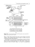
1) Dimensions of Neostat main unit with Wall-direct mounting kit
(2-position control type)
Note: When mounting the Neostat, be sure to
secure a longer than 15 mm clearance for
wiring from the mounting surface inside the
wall.
(77)
Wall-direct mounting kit
90
77
38.5
16.5
15
(77)
90
77
Insulated tube
Mounting surface
(Proportional control type)
Note: When mounting the Neostat, be sure to
secure a longer than 15 mm clearance for
wiring from the mounting surface inside the
wall.
(77)
Wall-direct mounting kit
Heat sink
38.5
16.5
15
(77)
77
90
90
77
Mounting
surface
(Connectors for connection check)
(Surface view of mounting plate)
φ4.2 mounting hole
Mounting screw (M3)
80
8.2
Mounting hole
∗ Use JIS outlet box/box cover (JIS C8340 (1999)).
Mounting dimension: 66.7 mm
(JIS: Japanese Industrial Standards)
66.7*
80
Figure 1. Dimensions (mm): Wall-direct mounting
4
AB-6475
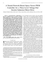
2) Dimensions of Neostat main unit with Thermoplate mounting kit
(2-position control type)
Note: When mounting the Neostat, be sure to
secure a longer than 12.5 mm clearance
for wiring from the mounting surface inside
the wall.
(77)
41
77
12.5
19
77
(77)
Insulated tube
Mounting surface
Thermoplate mounting kit
(Proportional control type)
Note: When mounting the Neostat, be sure to
secure a longer than 12.5 mm clearance
for wiring from the mounting surface inside
the wall.
(77)
41
77
Heat sink
12.5
(77)
77
19
Thermoplate mounting kit
Mounting
surface
(Connectors for connection check)
(Surface view of Thermoplate mounting kit)
8
49
22
φ2.8 mounting hole
Figure 2. Dimensions (mm): Thermoplate mounting
5
AB-6475
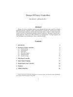
3) Dimensions of Neostat main unit (with the cover removed*) with Multi-Thermocase mounting kit
(Example of temperature controller Neostat installed in the Multi-thermocase)
∗ When multiple units of Neostat (and/or Neosensor) are installed in a Multi-Thermocase (separate order required), the
Neostat main unit covers are not used.
(72.8)
(85)
Multi-Thermocase
mounting kit
85
72.8
52
(72.8)
72.8
85
23
(Surface view of Multi-thermocase mounting kit)
55
φ3.4 mounting
hole
Assembled dimensions of device mounting
plate of Multi-Thermocase and
Multi-Thermocase mounting kit:
66.7 mm
68
∗
66.7*
Figure 3. Dimensions (mm): Multi-Thermocase mounting
6
AB-6475
Installation
Installation requirements
1) Mount Neostat on a wall approx. 1.5 m high above the floor, where the average temperature and humidity can be
measured.
2) Avoid locations where room air circulation is interfered by furniture or a door, and where heat from office automation
equipment stays on.
3) Avoid locations affected by draft, downdraft, hot/cold air from water pipes/ducts, and radiant heat from the sun.
∗
The ambient air velocity in the Neostat installation area should be between 0.1 and 0.2 m/s. (An installation
location with high air velocity could result in a shorter service life of the air-conditioning unit and control devices,
or in a controller hunting.)
4) Choose an installation location with no vibration.
5) Do not install Neostat where water may drop. Do not allow dew condensation on the Neostat main unit.
6) Do not install Neostat directly on the wall without Wall-direct mounting kit.
Installation procedure: Neostat directly on a wall (See Fig. 4.)
1) Attach the mounting plate to the box cover (outlet box mounting dimension: 66.7 mm (JIS C8340:1999)) located
inside the wall.
2) Install the main part of the Wall-direct mounting kit on the mounting plate. (See Fig. 9.)
3) Connect the output lead wires of the Neostat main unit to the external wires (for the load side). (See Fig. 16.)
4) Remove the cover from the Neostat main unit, and mount the main unit on the main part of the Wall-direct mounting
kit with the 4 main-unit accessory screws (M3 × 16). When mounting the main unit onto the Wall-direct mounting kit,
make sure to set the height-adjusting levers on the left and right sides (See Fig. 12.) to the upper positions (indicated
by "L").
5) Place the cover back on the Neostat main unit to complete the installation procedure. (See Fig. 8.)
External wires (for load side)
Mounting plate
Accessory: 2 pan-head machine screws (M4 × 8)
Main part of Wall-direct mounting kit
66
.7m
m
Accessory: 1 flat-head machine screw (M3 × 16)
Main unit of Neostat
Accessory: 4 flat-head machine
screws (M3 × 16)
Cover
Output lead wires
Neostat
Wall-direct mounting kit
(separate order required)
Mounting-box cover
JIS C8340
with 66.7-mm
mounting dimension
(commercially available)
Figure 4. Installation: Neostat with Wall-direct mounting kit
7
AB-6475
Installation procedure: Neostat on conduit connection type Thermoplate (See Fig. 5)
1) Attach the mounting plate to the conduit connection type Thermoplate.
2) Install the main part of Wall-direct mounting kit on the mounting plate. (See Fig. 9.)
3) Connect the output lead wires of the Neostat main unit to the external wires (for the load side). (See Fig. 16.)
4) Remove the cover from the Neostat main unit, and mount the main unit on the Wall-direct mounting kit with the 4
main-unit accessory screws (M3 × 16). When mounting the main unit onto the Wall-direct mounting kit, make sure
to set the height-adjusting levers on the left and right sides (See Fig. 12.) to the upper position (indicated by "L").
5) Place the cover back on the Neostat main unit to complete the installation procedure. (See Fig. 8.)
External wires (for load side)
Mounting plate
Accessory: 2 pan-head machine screws (M4 × 8)
Main part of Wall-direct mounting kit
Accessory: 1 flat-head machine screw (M3 × 16)
Main unit of Neostat
Accessory: 4 flat-head machine
screws (M3 × 16)
Cover
Output lead wires
Neostat
Wall-direct mounting kit
(separate order required)
Wire-pipe connection
(open-wiring) type
Thermoplate
(separate order required)
Figure 5. Installation: Neostat with Wall-direct mounting kit (on conduit connection type Thermoplate)
8
AB-6475
Installation procedure: Neostat on Thermoplate (See Fig. 6.)
1) Attach the mounting plate supplied with Thermoplate to the mounting box cover (switch box mounting dimension:
83.5 mm (JIS C8340:1999)) located inside the wall.
2) Mount Thermoplate on the mounting plate.
3) Install the main part of the Thermoplate mounting kit on the Thermoplate.
4) Connect the output lead wires of the Neostat main unit to the external wires (for the load side). (See Fig. 16.)
5) Remove the cover from the Neostat main unit, and mount the main unit on the main part of the Thermoplate mounting
kit with the 4 main-unit accessory screws (M3 × 16). When mounting the main unit onto the Thermoplate mounting
kit, make sure to set the height-adjusting levers on the left and right sides (See Fig. 12.) to the upper position
(indicated by "L").
6) Place the cover back on the Neostat main unit to complete the installation procedure. (See Fig. 8.)
External wires (for load side)
Mounting plate
Accessory: 2 pan-head machine screws
(M4 × 8)
Thermoplate
Accessory: 2 pan-head machine screws (M4 × 5)
83
.5m
m
Main part of Thermoplate mounting kit
Accessory: 2 tapping screws
(M2.6 × 8)
Main unit of Neostat
Accessory: 4 flat-head machine screws (M3 × 16)
Cover
Output lead
wires
Neostat
Thermoplate
mounting kit
(separate order
required)
Thermoplate
(separate order required)
Mounting-box cover
JIS C8340
with 83.5-mm
mounting dimension
(commercially available)
Figure 6. Installation: Neostat with Thermoplate mounting kit (on Thermoplate)
9
AB-6475
Installation procedure : Neostat in Multi-Thermocase (See Fig. 7.)
1) Attach the main part of the Multi-Thermocase mounting kit to the device-mounting plate of Multi-Thermocase.
2) Connect the output lead wires of the Neostat main unit to the external wires (for the load side).
3) Remove the cover from the Neostat main unit, and set the height-adjusting levers on the left and right sides to the
lower position (indicated by "H"). Then, mount the main unit on the Multi-Thermocase mounting kit with the 4
main-unit accessory screws (M3 × 16). Neostat installed in the Multi-Thermocase is used with the cover removed.
IMPORTANT:
When installing Neostat in the Multi-Thermocase, be sure to set the height-adjusting levers on the left
and right sides of the Neostat main unit to the lower position (indicated by "H").
Device-mounting plate
of Multi-Thermocase
Device-mounting plate
of Multi-Thermocase
Main part of
Multi-Thermocase
mounting kit
Multi-Thermocase
Accessory (Multi-Thermocase):
2 pan-head machine screws
(M3 × 6)
Main unit of Neostat
External wires
(for load side)
Accessory: 4 flat-head machine screws (M3 × 16)
Neostat
Multi-Thermocase mounting kit
(separate order required)
Height-adjusting levers
(set to the lower positions)
Note:
To mount the Neostat main unit, set the height-adjusting lever on the left and right sides to the lower
position before fixing the main unit on the Multi-Thermocase mounting kit with the 4 main unit
accessory screws.
Figure 7. Installation: Neostat (in Multi-Thermocase) with Multi-Thermocase mounting kit
10
AB-6475
Removing or installing the cover
• Removing the cover
Remove the cover by pressing the spring, using a thin
stick, located inside the top section of the Neostat
main unit.
• Installing the cover
Insert the two cover tabs into the two mounting holes
located at the bottom of the main unit and fix the cover
in place with the spring located at the top of the main
unit.
2) Pull out the Neostat main unit from the main part of the
Wall-direct mounting kit (Max. 9 mm).
Main part of Wall
-direct mounting kit
Neostat main unit
Pressing the spring
Figure 11. Pulling out the Neostat main unit
Cover tabs
(at 2 locations)
3) Lower the height-adjusting levers on the left and right.
∗ The height-adjusting levers are set to the upper
position (indicated by "L") for factory preset.
Cover
Height-adjusting lever
(set to the upper position
(indicated by "L"))
Main part of
Wall-direct
mounting kit
L
L
H
Figure 8. Removing/installing the cover
H
Height-adjusting lever (set to the lower position
(indicated by " H"))
Installing the main part of Wall-direct mounting kit
Figure 12. Height-adjusting lever
Mounting plate tabs
(at 2 locations)
4) Mount and fix the Neostat main unit on the main part
of the Wall-direct mounting kit with the 4 mounting
screws.
Rear side
Neostat main unit
Main part of Walldirect mounting kit
Mounting plate
Main part of Wall-direct mounting kit
Figure 9. Installing the main part of the Wall-direct mounting kit
4 mounting screws
Measures against disturbances (including heat
radiation and conductvity) caused by the mouting
wall
Figure 13. Neostat mounting on the Wall-direct mounting kit
5) Installation is completed with the Neostat raised
(Fig. 14).
∗ The effect of the raised Neostat varies depending on
the environment.
Against disturbances from the mounting wall, the position
(height) of the sensing element of the Neostat main unit
can be changed in accordance with the following procedure.
38.5
47.5
1) Remove the Neostat mounting screws (4 screws).
9 (Size of protrusion)
Wall surface
Wall surface
Main part of Wall-direct
mounting kit
Neostat main unit
Figure 14. Neostat with its main unit raised
∗ Follow the same procedure to install the Neostat on
the Thermoplate.
Mounting screws
Figure 10. Removing the mounting screws
11
AB-6475
Wiring
2
1) For the external wires, use stranded annealed copper wires with insulation, 1.25 mm or greater cross-section.
2) For open wiring, wiring installation needs to be performed with Yamatake’s auxiliary devices (separate order required)
Models DY2000A1021, DY2000A2021, and DY2000A3021 (conduit connection type Thermoplates).
3) Make sure that Neostat is correctly connected to the external wires and that all the wires are tightly connected.
Model TY6001
Model TY6000
Cooling
equipment
W
Bk
Model HY6000
R
O
Rises
Falls
Model TY9001
Heating equipment
Step 2
O
Step 2
(Changeover switch)
Cooling
equipment
G
Model HY9000
R
R
R
Dehumidifier
W
W
Humidifier
Falls
Falls
Falls
Falls
W
Rises
B
R
B
B
Model TY9000
Heating equipment
Step 1
Cooling/heating
equipment
Model TY6022
R
Falls
Cooling
equipment
Heating
equipment
Falls
Falls
W
Model TY6021
R
Step 1
R
B
B
W
B
B
Wire colors
R: Red
B: Blue
Bk: Black
W: White
O: Orange
G: Green
Figure 15. Internal wiring connection diagrams
<Room temperature controllers>
∗ Models TY6000Z and TY6001Z are 2-position 1-step temperature controllers capable of performing ON/OFF control
of motors, electric heaters, auxiliary relays, and the like.
∗ Models TTY6021Z and TY6022Z are 2-position 2-step temperature controllers capable of performing ON/OFF control
in dual steps of packaged air conditioners, motors, electric heaters, and the like. (Neostats for heating and for cooling
are categorized by their model numbers.)
∗ Models TY9000Z and TY9001Z are proportional-type controllers capable of performing control of valves, dampers,
and the like when connected to Yamatake’s Control Motor (Model MY3000E) and ACTIVAL (Models VY512X,
VY522X, or MY532X).
IMPORTANT:
If Model TY9000Z or TY9001Z is connected to a product other than the specified above, consult with
our sales personnel.
<Room humidity controllers>
∗ Model HY6000Z is a 2-position 1-step humidity controller capable of performing ON/OFF control of solenoid valves,
auxiliary relays, and the like.
∗ Model HY9000Z is a proportional-type humidity controller capable of performing proportional control of valves,
dampers, and the like when connected to Yamatake’s Control Motor (Model MY3000E) and ACTIVAL (Models
VY512X, VY522X, or MY532X).
IMPORTANT:
If Model HY9000Z is connected to a product other than the specified above, consult with our sales
personnel.
12
AB-6475
Connection to External Wires
1) Connection of 2-position 1-step Neostat Model TY6000Z or HY6000Z
Referring to Fig. 15 (Internal wiring connection diagrams) and according to the application (cooling/heating,
humidifying/dehumidifying), cut off the closed-end connectors of the output lead wires to be connected, and connect
the output lead wires to the external wires. Do not cut off the closed-end connectors left unconnected.
Output lead wire for
Neostat side
Connect.
∗ Use crimp terminals with insulation.
External wires (for load side)
Cut off to connect.
Closed-end connector
∗ Do not cut off the closed-end connectors left unconnected to the load side.
Figure 16. Connection of external wires to Model TY6000Z or HY6000Z
2) Connection of 2-position 1-step Neostat Model TY6001Z (with summer-winter changeover switch)
Connection of 2-position 2-step Model TTY6021Z and TTY6022Z
Connection of proportional Model TY9000Z, TY9001Z, and HY9000Z
Referring to Fig. 15 and according to the application (cooling/heating, humidifying/dehumidifying), connect the output
lead wires to the external wires.
CAUTION
•
When handling the proportional-type Neostat Model TY9000Z, TY9001Z, or HY9000Z, be careful not to
hurt yourself by touching the heat sink.
13
AB-6475
Setting
• Cooling/heating changeover
• Step-by-step temperature (Models TTY6021Z,
TTY6022Z)
1) Remove the cover.
2) Shift the setting slit of the changeover lever to the
specified position, either S (cooling) or W (heating),
marked in the Neostat main unit. (See Fig. 17.)
∗ Do not shift the changeover lever while the
equipment is in operation.
3) Place the cover back to complete the setting.
1) Remove the cover.
2) Move the step-by-step temperature-setting lever to set
the pointer at the desired number on the step-by-step
temperature-setting scale. (See Fig. 19.)
∗ Do not shift the step-by-step temperature-setting
lever while the equipment is in operation.
The step-by-step temperature is set to 1.5 °C for
factory preset.
3) Place the cover back to complete the setting.
Changeover
setting slit
W (Heating)
Changeover
lever
Model TTY6021Z (Heating 2-steps)
S (Cooling)
Changeover
setting slit
(Neostat
main unit)
Step-by-step temperature-setting lever
(Changeover lever)
∗ Set the changeover lever to align the setting slit with position S or W
according to heating or cooling.
Figure 17. Cooling/heating changeover
Step-by-step temperature-setting scale plate
• High/low limit stop and setting lock
Pointer
1) Remove the cover.
2) The controller is equipped with two setting-lock claws.
(See Fig. 18.)
The settig-lock claws are locked as follows for factory
preset.
Temperature controller:
30 °C
Humidity controller 30-80 %RH type:
80 %RH
Humidity controller 40-90 %RH type:
90 %RH
Before using the Neostat, slide the setting-lock claws
to the desired setting positions and set the
setting-range stop and setting-lock positions according
to the application. For a proportional controller, the
center of the proportional band is a setpoint (point at
which the temperature or humidity reaches down to
50 % (the center) of the proportional band).
Regarding the setpoints of the 2-position-type
controllers, refer to Figs. 20 to 23.
3) Place the cover back to complete the setting.
∗ The setting-lock claw is moved in the
directions of the arrow by lightly
pressing the claw.
(Knob of setting lever)
Step-by-step setting scale mark
∗ Set the pointer of the step-by-step temperature-setting lever at any of the temperature scale marks (1.5 °C, 2.0 °C, 2.5 °C) on the step-by-step temperature-setting scale plate. (This figure shows an example of setting at
1.5 °C.)
Model TTY6022Z (Cooling 2-steps)
Step-by-step temperature-setting lever
Step-by-step temperature-setting scale plate
∗ To fix (lock) a setting, set the pointer at
the desired position, and then place the
setting-lock claws on the left and right at
the center.
Variable setting range (Range stop)
Pointer
Setting lock (Fixed)
(Stopper)
(Stopper)
Setting-lock claw
(Knob of setting lever)
Setting memory
plate
Step-by-step setting scale mark
∗ Set the pointer of the step-by-step temperature-setting lever at any of the temperature scale marks (1.5 °C, 2.0 °C, 2.5 °C) on the step-by-step temperature-setting scale plate. (This figure shows an example of setting at
1.5 °C.)
Setting dial
(Pointer)
(Pointer)
Figure 18. Controller setting (Range stop, setting lock)
Figure 19. Step-by-step temperature setting
14
AB-6475
Differential (Nominal 1 °C (fixed))
Output lead wires
Model TY6000Z: Red - White "Closed"
Model TY6001Z: Red - Blue "Closed"
(Changeover switch on S side (Cooling))
Output lead wires
Model TY6000Z: Red - Blue "Closed"
Model TY6001Z: Red - Blue "Closed"
(Changeover switch on W side (Heating))
Setpoint
Temperature rise
Figure 20. Switching action of Models TY6000Z and TY6001Z
Differential (Nominal 5 %RH (fixed))
Model HY6000Z8000: at 50 %RH setting
Model HY6000Z8010: at 65 %RH setting
Output lead wires:
Red - White "Closed"
Output lead wires:
Red - Blue "Closed"
Setpoint
Humidity rise
Figure 21. Switching action of Model HY6000Z
Step-2 heater ON due to temperature fall
Step-2 heater OFF due to temperature rise
Step-2 switch
output lead wires
(Orange - Black)
Step-1 heater ON due to temperature fall
"ON"
Step-1 heater OFF due to temperature rise
”OFF”
Step-2 switch
output lead wires
(Red - Blue)
"ON"
”OFF”
Step-2 switch differential
(Nominal 1.5 °C (fixed))
Step-1 switch differential
(Nominal 1.5 °C (fixed))
Step-by-step differential
(Variable in steps of
1.5 °C, 2 °C, or 2.5 °C)
Setpoint
Temperature rise
Figure 22. Switching action of Model TTY6021Z (2-Step control of heating)
15
AB-6475
Step-2 refrigerator OFF due to
temperature fall
Step-2 refrigerator ON due to
temperature rise
Step-1 chiller ON due to
temperature rise
"ON"
Step-2 switch
output lead wires
(Orange - Green)
Step-1 chiller OFF due to
temperature fall
"OFF"
"ON"
Step-1 switch
output lead wires
(Red - White)
"OFF"
Step-2 switch differential
(Nominal 1.5 °C (fixed))
Step-1 switch differential
(Nominal 1.5 °C (fixed))
Step-by-step differential
(Variable in steps of 1.5 °C, 2 °C, or 2.5 °C)
Setpoint
Temperature rise
Figure 23. Switching action of Model TTY6022Z (2-step control of cooling)
Specifications are subject to change without notice.
Building Systems Company
Tamachi Kiyota Building
4-3-4, Shibaura
Minato-ku, Tokyo 108-0023
Rev.1.1 Apr. 2005
(J: AI-6475 Rev. 1.0)
16
16
AB-6475 0.5H-H
(W00)
AI-6475E