AS 1670 1 1995 fire detection, warning, control and intercom
Bạn đang xem bản rút gọn của tài liệu. Xem và tải ngay bản đầy đủ của tài liệu tại đây (846.19 KB, 82 trang )
Title
AS 1670.1-1995 Fire detection, warning, control and intercom systems - System
design, installation and commissioning - Fire
Licensee
Licensed to LUU MINH LUAN on 25 Feb 2002
Conditions of use
This is a licensed electronic copy of a document where copyright is owned or managed by
Standards Australia International. Your licence is a single user licence and the document may not
be stored, transferred or otherwise distributed on a network. You may also make one paper copy
of this document if required.
Web Check-up
AS 1670.1—1995
(Incorporating Amendment Nos 1, 2, 3 and 4)
AS 1670.1
Licensed to LUU MINH LUAN on 25 Feb 2002. Single user licence only. Storage, distribution or use on network prohibited.
Australian Standard™
Fire detection, warning control and
intercom systems—System design,
installation and commissioning
Part 1: Fire
This Australian Standard was prepared by Committee FP-002, Automatic Fire
Detection and Alarm Systems. It was approved on behalf of the Council of
Standards Australia on 13 March 1995 and published on 5 June 1995.
The following interests are represented on Committee FP-002:
Asset Services—Department of Administrative Services
Australian Building Codes Board
Australian Chamber of Commerce and Industry
Australian Chamber of Manufactures
Australian Electrical and Electronic Manufacturers Association
Australian Fire Authorities Council
Australian Fire Protection Association
Commonwealth Fire Board
CSIRO—Division of Building, Construction and Engineering
Licensed to LUU MINH LUAN on 25 Feb 2002. Single user licence only. Storage, distribution or use on network prohibited.
Federal Bureau of Consumer Affairs
Fire Protection Industry Association of Australia
Insurance Council of Australia
New Zealand Fire Equipment Association
N.S.W. Fire Brigades
Standards New Zealand
Telecom Australia
Keeping Standards up-to-date
Standards are living documents which reflect progress in science, technology and
systems. To maintain their currency, all Standards are periodically reviewed, and
new editions are published. Between editions, amendments may be issued.
Standards may also be withdrawn. It is important that readers assure themselves
they are using a current Standard, which should include any amendments which
may have been published since the Standard was purchased.
Detailed information about Standards can be found by visiting the Standards
Australia web site at www.standards.com.au and looking up the relevant Standard
in the on-line catalogue.
Alternatively, the printed Catalogue provides information current at 1 January each
year, and the monthly magazine, The Australian Standard, has a full listing of
revisions and amendments published each month.
We also welcome suggestions for improvement in our Standards, and especially
encourage readers to notify us immediately of any apparent inaccuracies or
ambiguities. Contact us via email at , or write to the Chief
Executive, Standards Australia International Ltd, GPO Box 5420, Sydney,
NSW 2001.
This Standard was issued in draft form for comment as DR 94182.
AS 1670.1—1995
(Incorporating Amendment Nos 1, 2, 3 and 4)
Licensed to LUU MINH LUAN on 25 Feb 2002. Single user licence only. Storage, distribution or use on network prohibited.
Australian Standard™
Fire detection, warning control and
intercom systems—System design,
installation and commissioning
Part 1: Fire
Originated as part of AS CA15—1961.
Previous edition AS 1670—1986.
Fourth edition 1995.
Reissued incorporating Amendment Nos 1, 2, 3 and 4 (November 2001).
COPYRIGHT
© Standards Australia International
All rights are reserved. No part of this work may be reproduced or copied in any form or by any
means, electronic or mechanical, including photocopying, without the written permission of the
publisher.
Published by Standards Australia International Ltd
GPO Box 5420, Sydney, NSW 2001, Australia
ISBN 0 7262 9754 2
AS 1670.1—1995
2
PREFACE
This Standard was prepared by the Joint Standards Australia/Standards New Zealand
Committee FP/2 on Automatic Fire Detection and Alarm Systems, to supersede AS 1670—1986.
Its preparation is concurrent with the issue of AS 1603 in a number of parts to cover the
requirements for specific items of equipment used in an automatic fire detection and alarm
system and installed in accordance with this Standard.
This Standard incorporates Amendment No. 1 (June 1997), Amendment No. 2 (June 1998),
Amendment No. 3 (May 2001) and Amendment No. 4 (November 2001). The changes
required by the Amendments are indicated in the text by a marginal bar and amendment
number against the clause, note, table, figure or part thereof affected.
This Standard is the result of a consensus among the members of the Joint Committee to
produce it as an Australian Standard.
Licensed to LUU MINH LUAN on 25 Feb 2002. Single user licence only. Storage, distribution or use on network prohibited.
Maintenance requirements for fire detection and alarm equipment are included in
AS 1851.8, Maintenance of fire protection equipment, Part 8: Fire detection and alarm
systems.
In this edition, sections have been arranged to provide users of the Standard with a logical
sequence as they work through the design, installation and commissioning of a fire alarm
system.
This Standard has been considerably expanded to include many practices that are in current
use and embrace additional scenarios where the previous edition was silent.
Appendix B ‘Guidance for the selection of detectors’ assists personnel engaged in the
design, installation and commissioning of fire protection and suppression systems.
The commissioning section encompasses Appendices F and G which are report forms to
indicate the installation content and its compliance with this Standard.
The terms ‘normative’ and ‘informative’ have been used in this Standard to define the
application of the appendix to which they apply. A ‘normative’ appendix is an integral part
of a Standard, whereas an ‘informative’ appendix is only for information and guidance.
3
AS 1670.1—1995
CONTENTS
Page
SECTION 1 SCOPE AND GENERAL
1.1 SCOPE .............................................................................................................. 5
1.2 APPLICATION .................................................................................................. 5
1.3 REFERENCED DOCUMENTS .......................................................................... 5
1.4 DEFINITIONS ................................................................................................... 5
1.5 COMPLIANCE WITH OTHER STANDARDS ................................................... 7
1.6 INTERPRETATION OF SPECIFIED LIMITING VALUES ................................ 7
Licensed to LUU MINH LUAN on 25 Feb 2002. Single user licence only. Storage, distribution or use on network prohibited.
SECTION 2 GENERAL REQUIREMENTS
2.1 COMPONENTS ................................................................................................. 8
2.2 SEPARATION OF SYSTEMS ............................................................................ 8
SECTION 3 ALARM ZONE LIMITATIONS
3.1 GENERAL ....................................................................................................... 10
3.2 ADDRESSABLE SYSTEMS ............................................................................ 10
3.3 DISTRIBUTED SYSTEMS .............................................................................. 11
3.4 INTERMIXING OF ACTUATING DEVICES................................................... 14
SECTION 4 LOCATION OF DETECTORS
4.1 GENERAL ....................................................................................................... 16
4.2 SPECIFIC LOCATIONS .................................................................................. 16
4.3 LOCATIONS WHERE PROTECTION IS NOT REQUIRED ............................. 19
SECTION 5 HEAT DETECTION SYSTEMS
5.1 GENERAL ....................................................................................................... 21
5.2 SPACING AND LOCATION OF DETECTORS................................................ 21
5.3 LINE-TYPE SYSTEMS—TUBULAR OR CABLE............................................ 23
SECTION 6 SMOKE DETECTION SYSTEMS
6.1 GENERAL ....................................................................................................... 27
6.2 SPACING AND LOCATION OF DETECTORS................................................ 27
6.3 MULTIPOINT ASPIRATED SMOKE DETECTORS ........................................ 30
SECTION 7 FLAME DETECTION SYSTEMS
7.1 GENERAL ....................................................................................................... 37
7.2 SPACING AND LOCATION OF DETECTORS................................................ 37
7.3 FIXING OF DETECTORS................................................................................ 37
7.4 DETECTOR LENSES ...................................................................................... 37
7.5 PROTECTION FROM WEATHER ................................................................... 37
SECTION 8 INSTALLATION REQUIREMENTS
8.1 GENERAL ....................................................................................................... 38
8.2 POWER SOURCE............................................................................................ 38
8.3 CONNECTION OF EXISTING INSTALLATIONS........................................... 40
8.4 FIRE INDICATOR PANEL .............................................................................. 40
8.5 SUBINDICATOR PANEL................................................................................ 42
8.6 ALARM VERIFICATION FACILITY .............................................................. 42
8.7 WARNING SYSTEMS..................................................................................... 42
AS 1670.1—1995
4
Page
8.8
8.9
8.10
8.11
8.12
8.13
8.14
8.15
8.16
8.17
8.18
8.19
MANUAL CALL POINTS ............................................................................... 43
REMOTE INDICATORS FOR FIRE DETECTORS .......................................... 43
SMOKE AND FIRE DOOR RELEASE CONTROL .......................................... 44
FIRE SUPPRESSION SYSTEM ....................................................................... 44
FIRE SUPPRESSION SYSTEM SUPERVISION .............................................. 45
CONTROL OF ANCILLARY DEVICES .......................................................... 45
VALVE MONITORING DEVICES .................................................................. 45
FLOW/PRESSURE SWITCHES ....................................................................... 45
FIP INDICATORS ........................................................................................... 45
WIRING .......................................................................................................... 46
MONITORING SERVICE ................................................................................ 47
WIRE FREE ALARM ZONE CIRCUITS .......................................................... 48
Licensed to LUU MINH LUAN on 25 Feb 2002. Single user licence only. Storage, distribution or use on network prohibited.
SECTION 9 COMMISSIONING
9.1 GENERAL ....................................................................................................... 49
9.2 COMMISSIONING OF INSTALLATION ........................................................ 49
9.3 STATEMENT OF COMPLIANCE.................................................................... 51
9.4 CIE DOCUMENTATION ................................................................................. 51
APPENDICES
A
LIST OF REFERENCED AND RELATED DOCUMENTS ...............................
B
GUIDANCE FOR THE SELECTION OF DETECTORS....................................
C
WIRING SYSTEMS RATING ..........................................................................
D
EXAMPLES OF POWER SOURCE CAPACITY CALCULATIONS .................
E
FIRE ALARM SYMBOLS ...............................................................................
F
COMMISSIONING TEST REPORT .................................................................
G
STANDARD FORM OF STATEMENT OF COMPLIANCE FOR
FIRE ALARM SYSTEMS ................................................................................
53
55
65
67
70
72
76
5
AS 1670.1—1995
STANDARDS AUSTRALIA
Australian Standard
Fire detection, warning control and intercom systems—System
design, installation and commissioning
Part 1: Fire
S EC TION
1
S C OP E
AND
G E NER A L
1.1 SCOPE
Licensed to LUU MINH LUAN on 25 Feb 2002. Single user licence only. Storage, distribution or use on network prohibited.
This Standard sets out requirements for the design, installation, and commissioning of
automatic fire detection and alarm systems comprising components complying with the
requirements of the appropriate product Standards.
1.2 APPLICATION
A1
All installations of automatic fire detection and alarm systems shall comply with the
general requirements of Section 2 and specific requirements of Section 3, Section 4 and
Section 8 with the additional requirements of Section 5, Section 6, or Section 7 according to
the actuating device type, and the commissioning requirements of Section 9. Manual call
points installed in conjunction with an automatic fire detection and alarm system or as a
separate system shall comply with the general installation requirements of this Standard.
Where an automatic fire detection and alarm system is ancillary to an automatic fireextinguishing installation, the detection system shall comply with the appropriate
requirements of this Standard.
1.3 REFERENCED DOCUMENTS
A list of the documents referred to in this Standard is given in Appendix A.
A1
1.4 DEFINITIONS
For the purpose of this Standard, the definitions given in AS 2484.2 and those below apply.
1.4.1 Addressable system
Fire detection and alarm system that can identify the location of individual actuating
devices on an alarm zone circuit (AZC).
1.4.2 Alarm investigation facility (AIF)
That part of the control and indicating equipment (CIE) which delays the transmission of a
fire alarm to provide time for manual acknowledgment and investigation.
1.4.3 Alarm signalling equipment (ASE)
Equipment designed to communicate alarm and fault signals and other information between
a fire alarm system and a monitoring service.
www.standards.com.au
© Standards Australia
AS 1670.1—1995
A1
6
1.4.4 Alarm verification facility (AVF)
That function of the CIE that verifies an alarm signal so that a spurious signal does not
initiate an alarm signal to the monitoring service or ACF functions and alarm warning
systems.
1.4.5 Approved and approval
Approved by, or the approval of, the regulatory authority.
1.4.6 Collective indication
Indication that is common to a group of actuating devices within a single alarm zone
without identification of the individual device.
1.4.7 Corridor
A narrow enclosed thoroughfare, other than a lift lobby, not exceeding 3.5 m in width, and
not used for trade or storage purposes.
1.4.8 Cupboard
Licensed to LUU MINH LUAN on 25 Feb 2002. Single user licence only. Storage, distribution or use on network prohibited.
An enclosure with a door or doors, which is an integral part of the building.
1.4.9 Distributed system
A fire detection and alarm system where sections of the CIE are remotely located from the
fire indicator panel or where subindicator panel(s) communicate with a main fire indicator
panel.
1.4.10 Extra-low voltage (ELV)
That voltage defined in AS 3000.
1.4.11 Level surface
Any surface, roof, or ceiling which has a slope of less than 1 in 20.
1.4.12 Low voltage (LV)
That voltage defined in AS 3000.
1.4.13 Monitoring service
A remote controlling station which receives fire alarm signals and transfers the signals to a
firefighting service via a permanently connected telecommunications link.
1.4.14 Occupied area
An area which is readily accessible for occupation, transit or service.
1.4.15 Power supply
That portion of the CIE which supplies voltages necessary for operation of the CIE.
1.4.16 Protected area
An area of a building equipped with an automatic fire detection and alarm system installed
in accordance with this Standard or an approved automatic fire suppression system.
1.4.17 Protected building
A building equipped throughout with an automatic fire detection and alarm system installed
in accordance with this Standard or an approved automatic fire suppression system.
© Standards Australia
www.standards.com.au
7
A1
AS 1670.1—1995
1.4.18 Remote controlled equipment (RCE)
Remotely located parts of CIE that provide the connection of alarm zone circuits and other
status monitoring circuits, or the connection of ancillary control and warning devices or any
combination thereof without required visual and audible indications and user control
facilities. Such facilities are provided at the FIP or SIP.
1.4.19 Sole occupancy unit
As defined in the Building Code of Australia (BCA) for a Class 2 and 3 building, and
Class 4 part of a building.
1.5 COMPLIANCE WITH OTHER STANDARDS
The fire detection and alarm system shall comply with the appropriate electrical safety
requirements specified in AS 3000 and the individual parts of the installation shall comply
with the appropriate Australian Standards listed in Appendix A.
Licensed to LUU MINH LUAN on 25 Feb 2002. Single user licence only. Storage, distribution or use on network prohibited.
1.6 INTERPRETATION OF SPECIFIED LIMITING VALUES
For the purpose of assessing compliance with this Standard, the specified values herein
shall be interpreted in accordance with the ‘rounding method’ described in AS 2706, i.e. the
observed or calculated value shall be rounded to the same number of figures as in the
specified limiting value and then compared with the specified limiting value. For example,
for specified limiting values of 2.5, 2.50, and 2.500, the observed or calculated value would
be rounded respectively to the nearest 0.1, 0.01, 0.001.
www.standards.com.au
© Standards Australia
8
AS 1670.1—1995
S EC TION
A1
2
GENER A L
R EQ U IR EMENTS
2.1 COMPONENTS
The individual equipment items shall be selected in order to achieve stable and reliable
performance. The selection of detectors, and their location, shall be such as to minimize
false operation. The components in the system shall be used in accordance with the
manufacturer’s specifications and shall be shown to be compatible in the configuration as
designed. Individual alarm indicators shall be latching, except where the detector is
required to be non-latching, e.g. supply air detection associated with smoke management,
and shall be provided by one of the following means:
(a)
Fire detectors selected to suit the particular hazard and risk to life or property, or
both. Detectors shall comply with the relevant product Standards.
Licensed to LUU MINH LUAN on 25 Feb 2002. Single user licence only. Storage, distribution or use on network prohibited.
NOTES:
(b)
1
The type of detectors recommended for use in various locations is described in
Appendix B.
2
For wire-free alarm zone circuits, installers need to be aware of the possibility of the
existence of neighbouring wire-free systems and select appropriate components to
minimize the risk of interaction between systems. It is recommended that signal
propagation and in-band noise and signals are measured at the proposed receiver
location(s) before installation to ensure that the system will be able to be operated
within the manufacturer’s specified limits.
Individual alarm indicators provided by one of the following means:
(i)
Integral with the detector, except where specific installation requirements
preclude their use, such as hazardous areas.
(ii)
Remote from the detector, except where specific installation requirements
preclude their use, such as hazardous locations, in accordance with Clause 8.9.
(iii) As unique alarm indication at the CIE, except where specific installation
requirements preclude their use, such as hazardous areas.
Where the detector is not required to latch in an alarm state (for example, supply air
detectors associated with a smoke management system), the indicator may be nonlatching.
A1, A3
A1
(c)
Control and indicating equipment complying with AS 1603.4 or AS 4428.1.
(d)
A fire warning system as specified in Clause 8.7.
(e)
A manual call point complying with AS 1603.5.
2.2 SEPARATION OF SYSTEMS
A1
A1
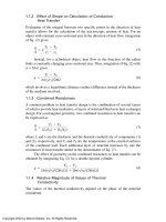
The fire detection and alarm system shall be independent of any building monitoring and
control systems (BMCS), and the control and indicating equipment shall be contained
within its own enclosure(s). Interfacing is permitted to provide data to the building
monitoring system or to initiate automatic testing of the fire detection and alarm system
(see Figure 2.1 for typical arrangement). Alarm and fault signals shall be displayed
independently of the BMCS.
Controls, indicators and equipment which form part of an associated fire protection system,
such as monitoring and control of—
© Standards Australia
www.standards.com.au
9
(a)
fire detectors;
(b)
fire extinguishing systems;
(c)
air handling plant; or
(d)
fire warning systems as required by Clause 8.7
AS 1670.1—1995
may be housed within the CIE enclosure provided all such controls, indicators and
equipment are segregated from other AS 1603 equipment.
A1
Licensed to LUU MINH LUAN on 25 Feb 2002. Single user licence only. Storage, distribution or use on network prohibited.
A1
NOTE: Metal enclosures, earthed screen cabling or 50 mm separation distance is taken to be
adequate segregation. Associated equipment installed in the same enclosure must not interfere
with the serviceability of and access to the field wiring. Any heat generated by associated
equipment must not cause any of the equipment within the enclosure to operate outside the
manufacturer’s specifications.
Where the fire detection and alarm system is used to control a smoke hazard management
system or a fire suppression system, additional consideration shall be given to cable
integrity and reliability in excess of the requirements of Clause 8.17, in accordance with the
operational requirements of the system under control.
A1
A1
A1
www.standards.com.au
FIGURE 2.1 EXAMPLE OF INTERFACE WITH BMCS
© Standards Australia
10
AS 1670.1—1995
S EC TION
3
A LAR M
ZONE
LIM IT AT IONS
3.1 GENERAL
An alarm zone shall be limited to a maximum 2000 m2 of contiguous floor area and shall be
confined to one storey.
Protected areas to which there is no access from inside the building shall have separate
alarm zone facilities from those having internal access.
The maximum number of actuating devices in an alarm zone shall be as approved for that
facility and in any case shall not exceed 40.
Licensed to LUU MINH LUAN on 25 Feb 2002. Single user licence only. Storage, distribution or use on network prohibited.
Detectors protecting concealed spaces not exceeding 500 m2 may be connected to the alarm
zone circuit on the same storey provided that the total protected area and the number of
detectors required do not exceed the alarm zone limits specified above. Remote visual
indicators shall comply with the requirements of Clause 8.9.
A mezzanine level may be connected to the alarm zone facility associated with the storey
from which access to the mezzanine is gained, provided that the total protected area and the
number of actuating devices required do not exceed the alarm zone limits specified above.
A1
Point type detectors shall be arranged and indicate as alarm zones. Individual detectors
shall not be displayed as separate alarm zones unless representing the only detector within a
compartment.
3.2 ADDRESSABLE SYSTEMS
Alarm zone circuits with more than one alarm zone shall comply with the following:
A1
(a)
A single open circuit shall register as a fault.
(b)
A single open circuit shall not prevent an alarm transmission from more than one
alarm zone.
(c)
Any condition including short or open circuit which prevents the transmission of an
alarm shall register as a fault on all alarm zones affected.
(d)
Any wire-to-wire short circuit shall disable not more than 250 devices on the alarm
zone circuit and in any case not more than one building.
(e)
Any wire-to-wire short circuit may register no more than a single alarm.
(f)
Unless the wiring of the alarm zone circuit is installed in two separate cable paths,
and each is protected against mechanical damage, WSX2 in accordance with
AS 3013, the alarm zone circuit shall not serve more than 10 storeys or more than a
20 000 m2 floor area in one building.
NOTE: Separation of cable paths should be that which is sufficient to protect the separate cables
from the anticipated mechanical damage in a likely single incident.
Addressable systems shall contain not more than 1000 devices on each alarm zone circuit
and such alarm zone circuit shall be limited to those buildings located on one site, under
one ownership.
Where addressable devices other than detectors are used on an addressable alarm zone
circuit, such as ancillary control devices, each such device shall count as one device.
© Standards Australia
www.standards.com.au
11
A1
AS 1670.1—1995
Where addressable systems are used to control other essential services such as a smoke
hazard management system or a fire suppression system, the integrity and reliability of the
addressable system shall be subject to the requirements of the relevant Standard.
3.3 DISTRIBUTED SYSTEMS
3.3.1 Classifications
Distributed systems are classified as follows:
Class 1 non-data transfer based system with subindicator panels.
Class 2 data transfer based system with subindicator panels.
Class 3 data transfer based system with remote control equipment (RCE).
3.3.2 General
Licensed to LUU MINH LUAN on 25 Feb 2002. Single user licence only. Storage, distribution or use on network prohibited.
Subindicator panels (SIPs) shall only be connected directly to the fire indicator panels
(FIPs) and not via any other SIP or remote part of the CIE unless the failure of such an
intermediate unit does not prevent the transmission of an alarm to the FIP. Such a failure
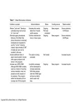
shall also indicate as a signal path fault (see Table 1).
Where a separate signal from an SIP is not provided to indicate a common isolated,
common AZC fault, and power supply failure, these signals shall also indicate as a signal
path fault at the FIP (see Table 1).
TABLE 1
FAULT TOLERANCE AND INDICATION REQUIREMENTS
FOR DISTRIBUTED SYSTEMS
Fault
Class
A1
Single open circuit
Single short circuit
1
2
3
1
2
3
FIP signal
Not more than
10 alarm zones
and not more
than 250
devices
Fault
Fault
not
applicable
Alarm or
fault
Fault
not
applicable
FIP signal
More than 10
alarm zones or
250 devices
Fault
Fault
Fault
Fault
Fault
Fault
SIP signal
More than 10
alarm zones or
250 devices
Fault
Fault
Fault
Fault
Fault
Fault
10 alarm
zones
maximum
10 alarm
zones
maximum
1 alarm
zone
maximum
10 alarm
zones or
250
devices
maximum
10 alarm
zones or
250
devices
maximum
10 alarm
zones or 250
devices
maximum
None
None
None
None
None
None
Alarm loss
Not more than
10 alarm zones
or 250 devices
Alarm loss
More than 10
alarm zones or
250 devices
www.standards.com.au
© Standards Australia
AS 1670.1—1995
12
3.3.3 Class 1 systems
The following applies to the signal path or signal paths between the FIP and the SIP:
Licensed to LUU MINH LUAN on 25 Feb 2002. Single user licence only. Storage, distribution or use on network prohibited.
A1
(a)
A single open circuit shall indicate as a signal path fault at the FIP.
(b)
A single open circuit shall indicate as a signal path fault at SIPs with more than
10 alarm zones or 250 devices.
(c)
A short circuit shall indicate as either a signal path fault or an SIP alarm at the FIP
for SIPs with no more than 10 alarm zones or 250 devices.
(d)
SIPs with more than 10 alarm zones or 250 devices shall be interconnected using two
separate cable paths. These cable paths shall be individually and suitably protected
against mechanical damage in accordance with AS 3013, the category being specified
in Appendix C.
NOTE: Separation of cable paths should be that which is sufficient to protect the separate cables
from the anticipated mechanical damage in a likely single incident.
(e)
A single short circuit on any of the cable paths from SIPs with more than 10 alarm
zones or 250 devices shall not prevent the transmission of alarm, and shall indicate as
a signal path fault at the FIP and the SIP.
(f)
Only one SIP shall be connected to each set of signal paths. Multiple SIPs mounted
adjacent to each other shall be considered as one SIP for the purpose of this
requirement.
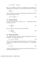
The connection between the FIP and the SIP may be as shown in Figure 3.1(a) and (b).
FIGURE 3.1 CLASS 1 SYSTEMS
© Standards Australia
www.standards.com.au
13
AS 1670.1—1995
3.3.4 Class 2 systems
The following applies to the signal path or signal paths between the FIP and the SIP:
A1
(a)
Any signal path fault shall indicate as a signal path fault at the FIP.
(b)
SIPs on a common path totalling more than 10 alarm zones or 250 devices shall be
interconnected using two separate cable paths. These cable paths shall be individually
and suitably protected against mechanical damage in accordance with AS 3013, the
category being specified in Appendix C.
NOTE: Separation of cable paths should be that which is sufficient to protect the separate cables
from the anticipated mechanical damage in a likely single incident.
(c)
A fault on any of the signal paths from SIPs with more than 10 alarm zones or
250 devices shall not prevent the transmission of an alarm and shall also indicate as a
signal path fault at the SIP.
(d)
Only one SIP shall be connected to a single signal path. Multiple SIPs mounted
directly adjacent to each other with a combined total not exceeding 10 alarm zones or
250 devices shall be considered as one SIP.
Licensed to LUU MINH LUAN on 25 Feb 2002. Single user licence only. Storage, distribution or use on network prohibited.
The connection between the FIP and the SIP may be as shown in Figure 3.2(a) and (b).
3.3.5 Class 3 systems
The following applies to the signal path or signal paths between the FIP and RCE:
A1
(a)
Any signal path fault, or remotely supplied power supply fault, shall indicate as a
signal path or power supply fault respectively, at the FIP.
(b)
RCEs on a common path totalling more than 10 alarm zones or 250 devices shall be
interconnected using two separate cable paths. These cable paths shall be individually
and suitably protected against mechanical damage in accordance with AS 3013, the
category being specified in Appendix C.
NOTE: Separation of cable paths should be that which is sufficient to protect the separate cables
from the anticipated mechanical damage in a likely single incident.
(c)
A single open circuit on any of the signal paths or remotely supplied power supply
lines for RCEs, shall not prevent the transmission of an alarm from more than one
alarm zone.
(d)
A single short circuit on any of the signal paths, or remotely supplied power supply
lines for RCEs, shall not prevent the transmission of an alarm from more than
10 alarm zones or 250 devices.
The connection between the FIP and the RCE may be as shown in Figure 3.3(a), (b) and (c).
3.3.6 Signal path fault indication
Where required by Clauses 3.3.3, 3.3.4 and 3.3.5, a fault in the FIP to SIP signal path shall
be indicated by a dedicated yellow/amber LED suitably labelled, or by the common fault
LED, provided the nature of the fault can be determined by other means, such as from an
alphanumeric display. The fault shall also indicate audibly as per AS 1603.4. Facilities to
silence or isolate the fault sounder shall be provided. A fault in the signal path shall
indicate within 60 s of such a fault occurring.
3.3.7 Signal path protection
Where the signal path is not duplicated or is not routed via separate fire-rated paths, the
signalling cables shall have a rating of not less than WS5XW in accordance with AS 3013.
www.standards.com.au
© Standards Australia
AS 1670.1—1995
14
Mechanical protection where required shall comply with Appendix C. Where installed
underground the signal path shall also comply with the requirements for category B systems
underground wiring (see AS 3000).
Where two separate paths are used and a single short circuit does not affect the alarm signal
from any zone or device, mechanical protection shall only be required where cables may be
subject to impact from equipment, vehicles or ladders, in the course of normal building
operation and maintenance. Hence cabling in false ceiling, roof spaces and the like will not
require mechanical protection to WSX2.
3.4 INTERMIXING OF ACTUATING DEVICES
Licensed to LUU MINH LUAN on 25 Feb 2002. Single user licence only. Storage, distribution or use on network prohibited.
Intermixing of the various devices on one alarm zone circuit is permitted, provided that the
devices are suitably rated for the system voltages and are compatible.
FIGURE 3.2 CLASS 2 SYSTEMS
© Standards Australia
www.standards.com.au
Licensed to LUU MINH LUAN on 25 Feb 2002. Single user licence only. Storage, distribution or use on network prohibited.
15
www.standards.com.au
AS 1670.1—1995
A1
FIGURE 3.3 CLASS 3 SYSTEMS
© Standards Australia
16
AS 1670.1—1995
SECTION
4
LOCAT ION
OF
DETECTORS
4.1 GENERAL
Licensed to LUU MINH LUAN on 25 Feb 2002. Single user licence only. Storage, distribution or use on network prohibited.
Detectors shall be located throughout all areas. Smoke detectors shall be installed in all
sleeping areas and egress paths serving sleeping areas, where no fixed cooking facilities are
installed. The following considerations shall apply in determining the location of detectors
to be installed:
(a)
Where an area is divided into sections by walls, partitions, or storage racks, reaching
within 300 mm of the ceiling (or the soffits of the joists where there is no ceiling),
each section shall be treated as a room, and shall be protected.
(b)
A clear space of at least 300 mm radius, to a depth of 600 mm, shall be maintained
from the detector or sampling point.
(c)
Detectors shall be mounted such that their indicators are visible from the path of
normal entry to the area they protect.
NOTE: Additional protection may be required where any special structural features or conditions
exist (see Appendix B).
4.2 SPECIFIC LOCATIONS
4.2.1 Accessible service tunnels
Accessible service tunnels, not fire-isolated, which provide communication between
buildings or sections thereof shall be protected (see Clause 4.2.8).
4.2.2 Air-handling systems
Detectors mounted in each air-handling system shall be connected to a separate alarm zone
facility (AZF) on the CIE.
Each smoke detector installed in a duct shall be fitted to an air-sampling device. Detectors
installed in air-handling systems shall be provided with permanent indelible labels, stating
fire alarm zone circuit designation and detector number, affixed adjacent to the detectors.
All self-indicating devices on smoke detectors located in air-handling systems shall be
clearly visible. Where this condition cannot be met, remote indicating devices are required,
and they shall be labelled appropriately.
Detectors shall be provided in the following locations within air-handling systems:
(a)
A1
Return-air system Buildings with a return air-handling system serving more than one
room shall have at least one smoke detector to sample air from each return air
opening for each storey in the building.
NOTE: Where return air smoke detectors are installed to comply with AS 1668.1 and they
meet the requirements of this Standard, then those detectors may be used to satisfy this
requirement.
(b)
Supply-air ducts Air-handling plant supplying air to more than one storey within the
building shall have a smoke detector installed as close as practicable to the plant to
detect smoke downstream of the supply air fan.
NOTE: Where supply-air smoke detectors are installed to comply with AS 1668.1 they may
be considered to satisfy this requirement. It is recommended that where AS 1668.1 does not
apply, the operation of any detector associated with the air-handling systems within the
building should shut-down the air-handling equipment to prevent the spread of smoke
throughout the building.
© Standards Australia
www.standards.com.au
17
(c)
AS 1670.1—1995
Exhaust ducts Ducts that are used for exhausting cooking fumes, flammable
vapours, lint material and the like shall have at least one detector at the furthest
practicable downstream point of the duct.
NOTE: Detectors for this application should be carefully selected to suit the environment so
that spurious alarms are minimized. A fully sealed heat detector would normally be used.
4.2.3 Concealed spaces
4.2.3.1 General
Protection shall be provided in all concealed spaces, except those areas specified in
Clause 4.3. Access for maintenance of detectors in concealed spaces shall be provided.
Where personnel entry to the concealed space is required the access dimensions shall be not
less than 450 mm × 350 mm.
Licensed to LUU MINH LUAN on 25 Feb 2002. Single user licence only. Storage, distribution or use on network prohibited.
4.2.3.2 Electrical equipment
Where a concealed space contains electrical lighting or power equipment that is fully within
the concealed space, and is connected to an electrical supply in excess of extra low voltage,
a detector shall be mounted on the ceiling of the concealed space within 1.5 m measured
horizontally from the equipment (see Clause 4.3(b)). An exception to this is when light
fittings are not rated above 100 W and power equipment with moving parts is not rated
above 100 W and stationary power equipment is not rated above 500 W.
For the purpose of this Standard, electrical wiring installed in accordance with AS 3000,
and any enclosures of light fittings not deemed combustible which protrude into a false
ceiling, are not regarded as electrical equipment.
NOTE: The detector used in the protection of the equipment in concealed spaces does not
necessarily constitute protection of the concealed space.
4.2.3.3 Remote indicators
Detectors installed in concealed spaces shall have remote indicators located in a position
clearly visible from the occupied area and close to or clearly indicating the location of the
detector. Remote indicators are not required where the concealed space is readily accessible
and—
(a)
has a height exceeding 2 m;
(b)
is beneath removable flooring (such as computer flooring); or
(c)
the detector’s location is indicated at the CIE.
Where detectors are mounted under removable flooring such as computer rooms, a label
shall be affixed to the ceiling or ceiling grid immediately above the detector indicating the
location of the detector below.
4.2.4 Cupboards
Any walk-in type cupboard with a floor area exceeding 2 m2 , or used for the storage of
flammable materials shall be internally protected.
Cupboards containing electrical or electronic equipment having voltages greater than extralow voltage shall be protected internally if in excess of 1 m3 .
NOTE: For electrical cubicles not requiring protection, see Clause 4.3.
www.standards.com.au
© Standards Australia
AS 1670.1—1995
18
4.2.5 External walls
Where the external walls of protected buildings are clad with combustible material they
shall be protected. The spacing of detectors shall be in accordance with the corridor spacing
specified in Clause 5.2.1. Detectors shall be located under the eaves or at the roof level.
NOTE: Heat detectors mounted under the eaves would normally be used for the protection of
external walls. Where eaves are not available to mount the detectors, line-type detectors should be
used at the top of the wall.
4.2.6 Intermediate horizontal surfaces
Protection shall be provided under intermediate horizontal surfaces such as ducts, loading
platforms, and storage racks in excess of 3.5 m in width and whose undersurface is in
excess of 800 mm above the floor.
Where the distance from the underside of the intermediate surface to the ceiling is less than
800 mm, the underside of the intermediate surface may be considered as the ceiling.
Licensed to LUU MINH LUAN on 25 Feb 2002. Single user licence only. Storage, distribution or use on network prohibited.
If the side of the duct or structure is in excess of 800 mm from the wall or other ducts or
structures, detectors shall be provided at the highest accessible point on the ceiling.
Where a concealed space is formed above or below the intermediate surface, such as ducts
above false ceilings in corridors, Clause 4.3 applies.
4.2.7 Monitor, sawtooth, or gable ceilings or roofs
Where a structure has a monitor ceiling or roof, a sawtooth ceiling or roof, or a gable
ceiling or roof, a row of detectors shall be installed between 0.5 m and 1.5 m from the apex
measured horizontally (see spacing requirements and typical detector locations in
Sections 5, 6, and 7).
4.2.8 Near doors
Where a door is permitted to be held open, and separates a protected area from an
unprotected area, a detector shall be placed inside the protected area not more than 1.5 m
from the door, see Clause 8.10.
NOTE: Additional detectors may be required for the control of automatic door closures.
4.2.9 Open grid (or egg crate) ceilings
Detectors may be omitted from the underside of open grid portions of the ceiling which
have not less than two-thirds of the ceiling area open to the free flow of air and have
detectors installed on the ceiling above the open grid.
Where any solid portion of the ceiling has a dimension in excess of 2 m and has an area in
excess of 5 m2 , normal protection shall be provided on the underside of the solid portion of
the open grid ceiling.
Where flame detectors are used they shall be installed both above and below the open grid
ceiling. The space above the open grid ceiling shall be protected, if required by this
Standard.
4.2.10 Restricted access
Where detectors are installed in areas to which fire brigade access is restricted, each area
shall be a separate alarm zone, or have a suitably labelled remote indicator installed outside
the entry to the area.
NOTE: Examples of restricted access may include, vaults, strongrooms, lift motor rooms, lift
shafts, locked cool rooms, freezers and high voltage switch rooms.
© Standards Australia
www.standards.com.au
19
AS 1670.1—1995
4.2.11 Sole occupancy units
Sole occupancy units consisting of one main room and water closet/shower/bathroom, with
a bounding FRL minimum of 60/60/60 may be protected by one detector located in the main
room provided that the total area of the whole unit is less than 46 m2 . The water
closet/shower/bathroom and the ceiling space containing a fan coil unit need not be
protected.
Detector(s) installed in each sole occupancy unit room shall be connected to a separate
alarm zone facility. Common alarm zone facilities may be used, provided that a clearly
labelled separate remote indicator is provided in the common access area outside each sole
occupancy unit.
NOTE: The location of the detector should take into account airflows and airstream.
4.2.12 Stairways
Non-fire isolated stairways shall be protected at each floor level within the stairway.
4.2.13 Vertical shafts and openings
Licensed to LUU MINH LUAN on 25 Feb 2002. Single user licence only. Storage, distribution or use on network prohibited.
Vertical risers, lift shafts, and similar openings between storeys, which exceed 0.1 m2 in
area, shall be protected within the riser at the top and as follows:
(a)
Where vertical shafts penetrate any storey and are not fire-isolated, a detector shall be
located on the ceiling of each storey not more than 1.5 m horizontally distant from
where the vertical shaft penetrates the storey above.
(b)
Any ceiling which contains openings exceeding 9 m2 and permitting free travel of fire
between storeys shall have detectors located within 1.5 m of the edge of the opening,
and spaced not more than 7.2 m apart around the perimeter of the opening. Such
detectors may be regarded as part of the general protection for the area below the
opening. If the opening is less than 0.5 m from a wall no detectors are required
between the wall and the opening.
4.2.14 Walkways
Enclosed covered walkways, irrespective of the type of construction, shall have a detector
in the covered way within 1.5 m of the adjoining protected area, except where the total
covered way is, itself, protected in accordance with this Standard. A covered walkway shall
be considered as enclosed if 90% of wall area above the height of the doorway into the
protected building is enclosed within 3 m of the building.
4.3 LOCATIONS WHERE PROTECTION IS NOT REQUIRED
Notwithstanding the foregoing requirements, detectors are not required in the following
locations:
(a)
Air locks Air locks, opening on both sides into protected areas, provided that they do
not contain electrical equipment, are not used for the storage of goods or for access to
cupboards and are not used as washrooms.
(b)
Concealed spaces Concealed spaces as follows (see Clause 4.2.3):
(i)
Concealed spaces other than between intermediate floors, which are less than
800 mm high, do not contain electrical lighting and power equipment and are
not used for storage.
(ii)
Concealed spaces between intermediate floors having a fire-resistance level of
not less than 120/60/30 and the ceiling below, which are less than 800 mm high
and which do not contain electrical lighting and power equipment.
www.standards.com.au
© Standards Australia
20
AS 1670.1—1995
(iii) Concealed spaces to which there is no access and which are fire-isolated with a
minimum fire-resistance level 60/30/15.
Licensed to LUU MINH LUAN on 25 Feb 2002. Single user licence only. Storage, distribution or use on network prohibited.
A1
A1
(iv)
Concealed spaces to which there is no access and which are less than 350 mm
high, irrespective of construction.
(v)
Concealed spaces which are less than 2.8 m3 , do not contain electrical lighting
and power and are not used for storage.
(c)
Covered ways Verandas, balconies, colonnades, open-sided covered walkways
(except as required by Clause 4.2.14), overhanging roof areas, and the like
constructed of non-combustible material and not used for the storage of goods or as a
car park.
(d)
Cupboards containing water heaters If a cupboard, opening off a protected area is
solely for the use of a water heater and does not exceed 2 m3 in volume, protection is
not required.
(e)
Exhaust ducts In ducts exhausting from toilets, or rooms containing single ironing
and laundry facilities.
(f)
Fire suppression system Any area protected by an approved automatic fire
suppression system (applies to heat detectors only).
(g)
Sanitary spaces Any water closet or shower-recess or bathroom, with a floor area of
less than 3.5 m2 and opening off a protected area.
(h)
Skylights Skylights as follows:
(i)
With an opening on the ceiling of less than 0.5 m2 and not used for ventilation.
(ii)
Installed in areas not requiring detection (such as sanitary spaces).
(iii) That have less than 4.0 m2 area, have a recess height of not more than 800 mm
and are not used for ventilation.
(iv)
(i)
With an opening on the ceiling of less than 0.15 m2 .
Switchboards Any non-recessed or freestanding switchboard or switchboard cubicle
protected by the normal protection of the area in which it is contained.
© Standards Australia
www.standards.com.au
21
SECTION
5
HEAT
DETECT IO N
AS 1670.1—1995
SYSTEMS
5.1 GENERAL
A1
Each detector shall be installed so that no part of the sensing element is less than 15 mm or
more than 100 mm below the ceiling or roof. Where roof purlins inhibit the free flow of
heat to the detector, the detector may be installed on the purlin provided that the sensing
element is not further than 350 mm from the roof. (See Section 3 for the maximum number
of detectors per alarm zone facility and alarm zone limitations.)
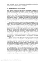
The maximum spacing and location of detectors shall comply with the requirements of
Clause 5.2 (see Figures 5.1, 5.2, and 5.3 for detector locations).
Detectors shall be installed in the highest point of the ceiling (see Figure 5.2); however,
where the ceiling is constructed with beams or joists or a step less than 300 mm deep, the
detector may be installed on the underside of the beam or joist.
Licensed to LUU MINH LUAN on 25 Feb 2002. Single user licence only. Storage, distribution or use on network prohibited.
Heat detectors, beneath roofs and ceilings subject to solar radiation, shall be installed with
the sensing element between 180 mm and 350 mm vertically below the roof or ceiling.
NOTE: The type of detector for use in various locations is described in Appendix B.
5.2 SPACING AND LOCATION OF DETECTORS
5.2.1 Spacing between detectors for level surfaces
For level surfaces, excluding corridors, detectors shall be arranged so that the distance from
any point on the ceiling of the protected area to the nearest detector does not exceed 5.1 m
(see Figure 5.1(a)). In addition, the distance between any detector and the nearest detector
to it shall not exceed 7.2 m.
For corridors, the distance between detectors shall not be more than 10.2 m
(see Figure 5.1(b)).
5.2.2 Spacing between detector for sloping surfaces
A1
The spacing between heat detectors for sloping surfaces in the longitudinal direction from
the heat detectors near the apex shall not exceed 7.2 m. The lower rows of heat detectors
shall be spaced not greater than 7.2 m measured horizontally from adjacent rows, the
outside wall or partition. The spacing between heat detectors in a longitudinal direction may
extend to 14.4 m in the lower rows, where the slope of the ceiling is ≥ 1 in 10 (see
Figure 5.2).
DIMENSIONS IN MILLIMETRES
FIGURE 5.1 (in part) TYPICAL DETECTOR SPACING—LEVEL SURFACES
www.standards.com.au
© Standards Australia
AS 1670.1—1995
22
DIMENSIONS IN MILLIMETRES
FIGURE 5.1 (in part) TYPICAL HEAT DETECTOR SPACING—LEVEL SURFACES
5.2.3 Spacing in concealed spaces requiring protection
Licensed to LUU MINH LUAN on 25 Feb 2002. Single user licence only. Storage, distribution or use on network prohibited.
Concealed spaces for which protection is required under Clause 4.2.3 shall be protected in
accordance with Clauses 5.2.1 to 5.2.5, subject to the following exceptions:
(a)
Concealed spaces with level upper surfaces in excess of 2 m high shall have detectors
spaced in accordance with Clauses 5.2.1 and 5.2.4.
(b)
For concealed spaces with level upper surfaces less than 2 m high and having
downward projections, such as beams and ducts not exceeding 300 mm from the
upper surface of the space, the spacing between detectors shall not exceed 10 m, and
the distance between any wall or partition to the nearest detector shall not exceed
5 m.
Where downward projections exceed 300 mm, the spacing of detectors shall be in
accordance with Clauses 5.2.1 and 5.2.5.
(c)
For concealed spaces with apices, the spacing between detectors in the longitudinal
direction at the apex shall not exceed 7.2 m. In a sloping surface, the lowest row of
detectors shall be located not more than 7.2 m measured horizontally towards the
apex from a position where the vertical height, between the upper and lower surfaces
of the space, is 800 mm. The spacing between detectors in a longitudinal direction
may be extended to 14.4 m in the lower rows. The distances between intermediate
rows parallel to the apex shall not exceed 7.2 m. The longitudinal spaces between the
detectors on the lower rows shall be arranged so that the detectors are spaced equally
between the detectors on the adjacent rows. (See Figure 5.2.)
5.2.4 Spacing from walls, partitions, or air supply openings
The distance from the nearest row of detectors to any wall or partition shall not exceed
3.6 m, or be less than 300 mm (see Figure 5.1(a)). For corridors, the distance between the
end wall and the nearest detector shall not exceed 5 m (see Figure 5.1(b)).
Detectors shall not be installed closer than 400 mm to any air supply opening.
5.2.5 Reduced spacing
For all types of heat detector, closer spacing may be required to take account of special
structural characteristics of the protected area. In particular, the following requirements
shall be observed:
(a)
Where the ceiling of the protected area is segmented by beams, joists, or ducts, and
the vertical depth of such members is greater than 300 mm, spacing between detectors
shall be reduced by 30% in the direction perpendicular to the direction of
segmentation.
(b)
The maximum coverage of a Type E detector shall be 9 m2 .
© Standards Australia
www.standards.com.au