DW144 specification for sheet metal ductwork1
Bạn đang xem bản rút gọn của tài liệu. Xem và tải ngay bản đầy đủ của tài liệu tại đây (4.4 MB, 102 trang )
1
DW/144
Specification for
Sheet Metal Ductwork
Low, medium and high
pressure/velocity air systems
1998
Copyright © 1998 by the
Heating and Ventilating
Contractors' Association
All rights reserved
ISBN 0-903783-27-4
Further copies of this publication are available from:
Publications Unit
Heating and Ventilating Contractors Association
Old Mansion House Eamont Bridge
Penrith Cumbria CA10 2BX
Tel: 01768 860405 Fax: 01768 860401
e-mail:
2
3
THE INDUSTRY
STANDARD
Ken Parslow
Chairman
Executive Committee
Ductwork Group
1996-98
For more than a decade-and-a-half, the DW/142 Specification for Sheet Metal Ductwork
published by the Heating and Ventilating Contractors' Association has gained national
and international recognition as the industry standard against which the quality of
ductwork manufacture and installation can be judged.
In recent years, however, it has become increasingly evident to the members of the
HVCA Ductwork Group that the developments in technology and working practices
which have taken place since the drafting of DW/142 have rendered obsolete significant
parts of the document.
It was an acknowledgement of this state of affairs which led the Technical SubCommittee of the Ductwork Group, ably chaired by Edgar Poppleton, to undertake the
task of producing a radically revised specification which would promote best practice
and quality standards well into the next Millennium.
This new publication - designated DW/144 - represents the direct result of that
initiative.
The new specification recognises the computer age - with special reference to
CAD/CAM procedures and techniques - and the international performance standards
established by the Committee for European Normalisation (CEN), as well as the need to
update and consolidate much of the information contained in the original DW/142
publication and its Addendum A companion volume.
During the drafting process, the Technical Sub-Committee has consulted widely with
individuals and organisations throughout the building services and construction sectors
in order to ensure that the new specification fully reflected the current the "state-of-theart" in terms both of technical expertise and industry best practice.
I firmly believe that this process has resulted in a publication which clearly
demonstrates the high level of professionalism which exists within the ductwork
community - and I take this opportunity of thanking all those who have contributed to
its production.
In particular, my thanks go to Edgar Poppleton and his colleagues on the Technical
Sub-Committee, to Keith Elphick for the provision of invaluable technical consultancy,
and to Ductwork Group secretary Gareth Keller for overseeing the project as a whole.
3
4
MAINTAINING QUALITY
Like most industries, the ductwork sector must
be prepared continually to innovate in order to
survive and prosper.
A key element in that innovation process is
the timely review and updating of quality
standards to ensure that they continue to offer
realistic benchmarks to which all professional
individuals and organisations can perform.
The development of this new Specification for
Sheet Metal Ductwork - designated DW/144 - has
been carried out with that objective in mind.
In the 16 years since the publication of its
predecessor, DW/142 - and in the ten years since
the supplementary volume Addendum A appeared many technical advances, changes in working
practices and regulatory introductions and
amendments have taken place.
The common performance standards for ductwork being developed by the Committee for
European Normalisation (CEN), for example,
had to be taken fully into account during the
drafting process. Similarly, notice had to be
given to the provisions of the Control of
Substances Hazardous to Health (COSHH) and
Construction
(Design and
Management)
Regulations, neither of which had been issued
when DW/142 was published.
It is not possible - nor, I think, desirable - to
include in this foreword an exhaustive catalogue
of the points of difference between this
specification and its predecessor. These will
clearly emerge from a detailed reading of the
text.
I should, however, like to take the
opportunity to highlight a few topics which I
believe to be of particular significance. They are:
• the omission of high-pressure Class D (in
order to conform to European practice);
• the highlighting of information to be
provided by the designer;
• the end-sealing of ducts and explosion risks;
• the removal of standard sizes of rectangular
ducts;
• the omission of cleated joints;
• the acceptance of proprietary flanges
certificated to DW/TM I no longer illustrated
in detail;
• the consolidation into the document of
coverage of hangers and supports;
• the addition of a note on linings, along with
their cleaning considerations;
• the consolidated graphical representation of
Class A, B and C air leakage characteristics,
mandatory testing Class C only;
• updated appendices on galvanising after
manufacture, stainless steel, pre-coated steel,
aluminium, Eurovent and galvanised material,
plus a bibliography;
• transport, handling, storage and interface with
DW/TM2 Guide to Good Practice – Internal
Cleanliness of New Ductwork Installations;
• an overview of fire-rated ductwork;
• a new appendix on inspection, servicing and
cleaning access openings (the default inclusion
of Level 1 should be noted);
• a new section on standard component drawings
- incorporating a framework of nomenclature,
and a description of drawing symbols,
abbreviations and rules - which is intended to
reduce ambiguity and promote common
understanding;
• a rewritten description of all forms of dampers,
for which I am indebted to Bill Clark and John
Mawdsley of the HEVAC Association.
I take this opportunity to acknowledge the permission granted by the Sheet Metal and Air
Conditioning Contractors' National Association
(SMACNA) of the USA for the use of its tie rod
specification (designer approval required).
And I also include a plea on behalf of ductwork
constructors to be allowed to make the final choice
of components and techniques within the parameters set by the designer, and allowed within this
specification to satisfy performance characteristics.
It will, of course, be clear to anyone who has
ever taken on such a task that the production of
this specification has involved a colossal input in
terms of industry consultation and from a wide
variety of individuals, a number of whom I should
like to identify for special mention.
They are: former Technical Sub-Committee
members Keith Waldron and the late Keith
Angood; current members Chris Collins, Stuart
Howard, Brian James and - last but by no means
least - Jim Murray; technical consultant Keith
Elphick; and Ductwork Group secretary Gareth
Keller.
Finally, may I remind readers of the crucial
importance of ensuring that all ductwork is manufactured and installed in a manner which is safe,
efficient, effective and free of risk.
The publication of DW/144 is intended to assist
significantly in the achievement of this objective.
5
Acknowledgements
The HVCA wishes to record its sincere thanks to the following
members - past and present - of the Technical Sub-Committee
of the Ductwork Group, who contributed their time, knowledge
and experience to the production of this document
Edgar Poppleton (chairman)
Keith Angood
Chris Collins
Stuart Howard
Brian James
Jim Murray
Keith Waldron
Technical Consultant:
Keith Elphick
Ductwork Group Secretary:
Gareth Keller
6
7
Contents
Page
Notes
10
Part One - Technical Information to be provided
by the designer
1. Introduction
11
2. Standards
11
3. Components
11
4. Particular Requirements
11
Part Two - Standards
5. Application
6. Ductwork Classification and Air Leakage
7. Materials
8. Ductwork Construction and Joint Sealing
Part Three - Rectangular Ducts
9. Rectangular Duct Sizes
10. Construction
10.1 General
10.2 Steel Thicknesses
10.3 Longitudinal Seams
10.4 Cross Joints
10.5 Stiffeners
10.6 Ductwork Galvanised After
Manufacture
10.7 Fastenings
11. Fittings
11.1 Standardisation of Fittings
11.2 Stiffeners
11.3 Splitters
11.4 Turning Vanes
11.5 Branches
11.6 Change Shapes
11.7 Expansions and Contractions
11.8 Sealant
Part Four - Circular Ducts
12. Standard Sizes
13. Construction
13.1 Longitudinal Seams
13.2 Cross Joints
13.3 Fastenings
14. Fittings
14.1 Standardisation of Fittings
14.2 Nominal Diameters
14.3 Sheet Thickness
14.4 Sealing of Joints
Part Five - Flat Oval Ducts
15. Standard Sizes and Sheet Thicknesses
16. Construction (Spirally wound)
16.1 General
16.2 Longitudinal Seams
16.3 Cross Joints
16.4 Fastenings
16.5 Stiffening
17. Construction (Straight Seamed)
18. Fittings
18.1 General Construction Requirements
18.2 Standardisation of fittings
35
35
35
35
35
35
Part Six - Hangers and Supports
19. General
43
Part Seven - General
20. Access/Inspection Openings
21. Regulating Dampers
22. Fire Dampers
23. Smoke Dampers
24. Combination Smoke and Fire Dampers
25. Flexible Ducts
26. Flexible Joint/Connections
27. Protective Finishes
28. Connections to Building Openings
29. Internal Duct Linings
30. Thermal Insulation
31. Kitchen Ventilation
32. Fire Rated Ductwork
33. Standard Component Drawings
and Abbreviations
13
13
13
14
15
15
15
15
15
15
15
16
16
16
16
16
16
16
16
16
17
17
Part Eight - Appendices
Appendix A. Air Leakage from
Ductwork
Appendix B. Identification of
Ductwork
Appendix C. Guidance Notes for the
Transport, Handling and
Storage of Ductwork
Appendix D. Ductwork Systems and
Fire Hazards
Appendix E. Hot Dip Galvanizing after
Manufacture
Appendix F. Stainless Steel for Ductwork
Appendix G. Pre-Coated Steel
Appendix H. Aluminium Ductwork
Appendix J.
Eurovent
Appendix K. Summary of BS.EN10142:
1991 Continuously Hot-Dip
Zinc Coated Mild Steel Strip
and Sheet for Cold Forming
Appendix L. `Design Notes for Ductwork'
(CIBSE Technical
Memorandum No. 8)
Appendix M. Guidance Notes For Inspection,
Servicing and Cleaning Access
Openings
Appendix N. Bibliography
Appendix P. Conversion Tables
27
27
27
27
27
29
29
29
29
29
35
35
35
35
35
8
47
48
49
50
51
51
52
53
53
54
54
54
54
54
75
80
82
83
85
86
89
90
91
92
93
94
95
97
List of Tables
Table
Page
Part Two - Standards
1. Ductwork Classification and Air
Leakage Limits
2.
3.
4.
5.
Part Three - Rectangular Ducts
Constructional Requirements
Low Pressure up to 500Pa
Constructional Requirements
Medium Pressure up to 1000Pa
Constructional Requirements
High Pressure up to 2000Pa
Fastening Centres
Part Four - Circular Ducts
6. Standard Sizes
7. Spirally-Wound Ducts
8. Straight-Seamed Ducts
9. Permitted fastenings and maximum
spacings
10. Fittings Sheet Thicknesses
Part Five - Flat Oval Ducts
11. Standard sizes and sheet thicknesses
12. Stiffening requirements
low and medium pressures
13. Stiffening requirements
high pressure
14. Permitted fastenings and maximum
spacings
13-17
18-24
25-28
29
30
Socket and spigot cross joints
Stiffeners
Tie rod assembly
Hard and Easy bends
Turning Vanes
31
32-38
39-45
Part Four - Circular Ducts
Spiral and straight seams
Cross joints spirally wound ducts
Cross joints straight seamed ducts
29
30-31
32-33
53-58
59-63
Part Five - Flat Oval Ducts
Cross joints spirally wound ducts
Cross joints straight seamed ducts
39-40
41-42
Part Six - Hangers and Supports
Horizontal ducts
bearers and hangers
Vertical ducts supports
45-46
46
13
18
19
19
24
64-75
27
28
28
76-77
Part Seven - General
Fire barrier/Fire damper expansion
Flexible joint connections
Standard component drawings Rectangular
125-152 Standard component drawings Circular
153-167 Standard component drawings Flat Oval
168-177 Plant/equipment/miscellaneous
78-79
80
81-124
29
29
36
37
38
40
178
Part Six - Hangers and Supports
15. Supports for horizontal ducts - rectangular,
flat oval and circular
Part Seven - General
16. Standard Abbreviations
Part Eight - Appendices
17. Air Leakage Rates
18. Recommended duct identification colours
19. Examples of further identification symbols
20. Ductwork galvanized after manufacture rectangular
21. Compositions of the commonly used
Stainless Steel grades
22. Rectangular aluminium ducts low pressure constructional requirements
23. Circular aluminium ducts low pressure constructional requirements
24. Zinc coating mass (weight)
25. Access requirements for inspection,
servicing and cleaning
179
44
72-73
76
80
81
85
88
90
91
93
94
List of Illustrations
Figs
1-8
9
10-12
Pages
Part Three - Rectangular Ducts
Longitudinal Seams
Illustrations of panel stiffening
Flanged cross joints
22
23
24
25
25
20
20
21
9
Part Eight - Appendices
Permitted leakage at various
pressures
Example of duct identification symbol
50
52
55-61
62-67
68-70
71
78
81
Notes
In this document:
(1) Even where a ductwork job specification calls for the system to be
wholly in accordance with DW/144, it will still be necessary for the
designer, in addition to providing drawings showing details and
dimensions of the ductwork, to identify specific requirements, particular to his or her design.
The technical information to be provided by the designer is therefore
set out in detail on page 11.
(2) All dimensions quoted in this specification refer to the nominal sizes,
which are subject to the normal relevant commercial and published
tolerances.
(3) Manufacturing techniques are continually subject to change and
improvements and in respect of proprietary methods and devices this
specification does not preclude their use if they can be demonstrated
to the designer to be equally satisfactory. Where there is divergence
between the requirements of DW/144 and the manufacturer's
recommendations for proprietary methods and devices, the latter shall
take precedence.
(4) The expressions `low-pressure,' 'medium-pressure' and 'highpressure'
relate to the pressure/velocity classes set out in Table 1.
(5) `Mean air velocity' means the design volume flow rate related to the
cross-sectional area.
(6) Reference to the air distribution system pressure relate to the static
pressure of the relevant part of the ductwork system and not to the
fan static pressure.
(7) The symbol for litres is ‘L’: 1000 litres per second is equivalent to 1
cubic metre per second.
(8) The pascal (Pa) is the internationally agreed unit of pressure. The
relationship of the pascal to other units of pressure is: 500 pascals =
500 Newtons per square metre = 5 millibars = approximately 2
inches water gauge.
10
Part One - Technical information to be
provided by the designer to the ductwork contractor
1 INTRODUCTION
The selection of constructional methods is the decision
of the Manufacturer to conform with the performance
requirements of the specified ductwork classification.
Sections 2-4 below define the information that is to be
provided by the Designer.
2 STANDARDS
2.1 Pressure classification (Table 1)
2.2 Leakage classification (Table 1)
2.3 Positive and Negative pressures (Table 1)
2.4 Materials (Section 7)
2.5 Any special system requirements
3 COMPONENTS
3.1 Inspection/servicing access openings (Section
20 and Appendix M)
Number and location of all panels and covers for
inspection and/or servicing access other than those
covered in Section 20 and summarised as Level 1
requirements in table 25 of Appendix M. Number
and location of test holes, instrument connections
and hinged doors as defined in Section 20.
3.2 Cleaning access
(Section 20.8 and Appendix M)
Designers shall stipulate their requirements for
periodic internal cleaning of ductwork and for the
consequent need for adequate access for specialist
cleaning equipment.
3.3 Regulating dampers (Section 21) Specification,
location and mode of operation of all regulating
dampers.
3.4 Fire dampers (Section 22)
Specification and location of all fire dampers to
meet the requirements of the Authority directly
concerned with fire protection.
3.5 Smoke dampers (Section 23)/Combination
smoke and fire dampers (Section 24)
Specification and location of all smoke dampers to
meet the requirements of the Authority directly
concerned with fire protection.
3.6 Flexible ducts (Section 25)
Specification and location of any flexible ductwork.
3.7 Flexible joint connections (Section 26)
Specification and location of any flexible connections eg. plant or building expansion joints.
4. PARTICULAR REQUIREMENTS
4.1 Air leakage testing (Section 6 and Appendix A)
The extent of any air leakage testing. While it shall
be mandatory for high-pressure ductwork (as
defined in this specification) to be tested for air
leakage in accordance with the procedure set out in
DW/143, A practical guide to Ductwork Leakage
Testing, no such testing of low- or medium-pressure
ductwork is required.
4.2 Protective finishes (Section 27)
Details and specification of any protective finishes.
4.3 Fire rated and smoke extract ductwork
(Appendix D)
The extent and limits of protection for any fire
resisting ductwork.
4.4 Internal thermal/acoustic lining
(Section 29)
The extent of any ductwork requiring internal
acoustic/thermal lining is to be clearly identified. A
detailed specification of materials and method of
application is required. The practical aspects of
cleaning or maintenance must be addressed by the
designer before deciding to internally line ductwork.
4.5 External thermal/acoustic insulation
(Section 30)
The extent and thickness of insulation to be provided
by others should be stated.
4.6 Special supports (Section 19)
Details of any spanning steel or special support
requirements not covered by Section 19
4.7 Attachment to building structure (Section 28)
Specific requirements for the junction of ductwork
and associated components to openings should be
detailed and specified and the limits of responsibility
defined.
The provision of penetrations and associated
framings are outside the scope of this specification.
4.8 Air terminal units
Detail and specifications of all Air Terminal Units. It
is expected that all Air Terminal Units and their
Plenums (See Figures 120 to 124) will be supported
by the Ceiling Grids unless the designer indicates an
independent method of support.
4.9 Ductwork layout drawings
Details of any special requirements relating to CAD,
scales, etc. It is common practice and cost effective
for ductwork manufacturers to utilise their approved
ductwork layout drawings as a basis of their
manufacturing/installation information by adding the
necessary details to the same drawing. Scales of 1:50
or smaller may preclude this practice, therefore,
larger scales might be more appropriate. The final
choice of manufacturing/installation scales shall be
left to the ductwork contractor.
4.10 Other requirements
Details of any requirements for the ductwork not in
accordance with the provisions of this specification,
including any modified construction required to
conform with any requirements concerning external
ductwork (See 5.3) or to meet the regulations of a
local authority or other controlling body.
11
4.11 Reference to the designer
In consideration of the foregoing, reference is also
made to the designer in the following clauses:
Clause
5.3
7.4, 7.5, 7.6
10.5.2
11.1
14.1
16.3.1
19.1, 19.4
19.6, 19.7
20.1, 20.1.1.1, 20.6, 20.8
20.9
21.1, 21.3.1
21.3.4
22.3, 22.7
24.3
25.1
26.1
27,27.3.4
29.1, 29.4, 30.2, 30.3, 33.2
Fig. 176
Appendix A
Appendix B
Appendix C
Appendix D
Appendix E
Appendix F
Appendix L
Appendix M
12
Page
13
14
16
16
29
35
43
44
47
48
48
49
50
51
51
52
53
54
71
75-79
80,81
82
83,84
85
86-88
93
94
Part Two - Standards
5 APPLICATION
5.1 This specification sets out minimum requirements
for the manufacture and installation of ductwork for
commercial and industrial air distribution systems,
made from any of the materials listed in Section 7 and
being within the limits of size and/or metal
thicknesses specified in the relevant tables. Normal
operating temperatures are assumed within the
pressure/velocity limits and the limits of air leakage
for the various pressure classes prescribed in Table 1.
5.2 This specification is not intended to apply to
ductwork handling air which is polluted or is otherwise exceptional in respect of temperature or
humidity (including saturated air); nor is it suitable
for ductwork exposed to a hostile environment, e.g.
contaminated air, off-shore oil rigs, etc. The design,
construction, installation, supports and finishes in
such cases should be given special consideration in
relation to the circumstances of each case.
5.3 This specification is not suitable for ductwork
exposed to external atmosphere and the Designer will
need to give specific details of any special
finishes/construction (See Section 27).
6 DUCTWORK CLASSIFICATION AND AIR
LEAKAGE
6.1 Classification and air leakage limits Ductwork
classification and air leakage limits are set out in
Table 1.
6.2 Compatibility with CEN
The leakage factors used in Table 1 for Classes A, B
and C are the same as those for the classes similarly
designated in the CEN Document Pr EN 12237/Pr EN
1507.
6.3 Leakage at various pressures; and other
relationships
Applying the limits specified in Table 1, Appendix A
(Table 17) sets out the permitted leakage at each of a
series of pressures up to a maximum for each class.
Included in that appendix is a graphical presentation
of the pressure/leakage relationship.
DW/143 A practical guide to Ductwork Leakage
Testing, also gives details of the basis for the leakage
limits specified in Table 1.
6.4 Air leakage testing
Air leakage testing of low and medium pressure
ductwork is not mandatory under this specification.
Air leakage testing of high pressure ductwork is
mandatory under the specification and for details of
testing procedure refer to DW/143 A practical guide
to Ductwork Leakage Testing.
7 MATERIALS
7.1 Application
This specification applies to ductwork constructed
from materials as defined below, or equal. Minimum
steel thickness is to be taken as a nominal thickness
within the tolerances to BS.EN10143:1993. (See
Appendix K)
7.2 Zinc-coated steel
Ductwork will normally be constructed from hotdip galvanized steel to BS.EN10142:1991, Grade
DX51 D+Z, coating type Z275.
13
7.3 Mild steel
Where mild steel is specified, it shall be cold-reduced
steel to BS.EN10130:1991, Grade FEP 01A.
8.2.2 Liquid and mastic sealants
These are typically applied to a longitudinal seam
formed between two sheets of metal, a socket and
spigot, cleated or flanged cross joints. Particular
care is needed when sealing of "corner pieces" on
the proprietary 'slide-on' type flange and
reference should be made to the manufacturer's
assembly and sealing instructions.
7.4 Stainless steel
Where stainless steel is specified. it will be the
responsibility of the designer to indicate the type most
suitable for the conditions to which the ductwork will
be exposed. In doing so, it is recommended that the
factors set out in Appendix F should be taken into
account. In this connection, reference must be made to
BS 1449: Part 2, which includes stainless steel.
8.2.3 Gaskets
These can be of various materials in the form of a
preformed roll, sheet or strip, applied between
opposing faces of flanged cross joints. In the case
of proprietary 'slide-on' type flanges, it is
advisable to use the gasket strip recommended by
the manufacturer.
7.5 Pre-coated steel
Pre-coated steel may be specified for aesthetic or
other reasons. The designer must then consider the
availability of suitable materials and the restriction on
fabrication methods. Guidance notes are available in
Appendix G.
Factory-fitted proprietary synthetic rubber '0'ring
type gaskets are also acceptable for socket and
spigot joints on circular duct systems.
7.6 Aluminium
Where aluminium is specified, it will be the
responsibility of the designer to define the type most
suitable for the conditions to which the ductwork will
be exposed. Reference must be made to BS.EN485,
BS.EN515 and BS.EN573 for aluminium sheet and
BS.EN755 Parts 3-6 for aluminium section.
(Constructional requirements for ductwork made from
aluminium sheet and general notes on the material are
set out in Appendix H.)
8.2.4 Tapes
8.2.4.1 The application of tapes - Best suited,
but not limited, to cross joints on circular or flat
oval ductwork. Where chemical reaction tape,
heat shrinkable tape or other approved material
is used on flat oval ductwork care should be
taken to maintain close contact between the
material and the flat sides of the duct until the
joint is completed.
8.2.4.2 Chemical reaction tape - An
impregnated woven fibre tape and a resin type
activator/adhesive. On application of the
activator/adhesive the tape becomes pliable and
can then be applied to any surface shape. The
liquid reacts with the tape, causing the 2part
system to `set'.
8 DUCTWORK CONSTRUCTION AND JOINT
SEALING
8.1 Ductwork construction
The selection of longitudinal, cross joint and stiffener
types within the criteria laid down in the tables should
be the responsibility of the manufacturer.
8.2 Joint sealing and sealants
8.2.1 General
The integrity of the ductwork depends on the
successful application of the correct sealant,
gaskets or tape. The materials used should be
suitable for the purpose intended and satisfy the
specified pressure classification.
Illustrations indicating sealant locations will be
found in the following sections dealing with the
construction of rectangular, circular and flat oval
duct sections.
IN ALL CASES, SEALANT MATERIALS
MUST
BE
APPLIED
STRICTLY
IN
ACCORDANCE
WITH
THE
MANUFACTURER'S INSTRUCTIONS AND COSHH
ASSESSMENT.
8.2.4.3 Heat shrinkable band/tape - A thermoplastic material, coated on the inside with
hot metal adhesive. The band (or an appropriate
length of tape) is cut from the roll and wrapped
around the joint. When heated the tape shrinks
tightly around the joint thus providing a seal.
8.2.4.4 Self adhesive tape - Manufactured
from various materials including cloth based,
PVC and aluminium foil. Typically applied
externally to socket and spigot cross joints.
However, it is difficult to provide the dry, dust
and grease free surface that is required for a
successful application and this method is
therefore not recommended as a primary source
of sealant.
NB! Risk of explosions
Where ductwork is blanked off prior to leakage
testing or to prevent the ingress of contamination,
care should be taken to ensure that all joint sealing
solvent vapours are dispersed from the ductwork
systems.
14
Part Three - Rectangular Ducts
9 RECTANGULAR DUCT SIZES
This specification covers duct sizes up to a maximum
longer side of 3,000 mm. Duct sizes with an aspect
ratio greater than 4:1 are not recommended. Although
they offer no problems of construction, they increase
frictional resistance and the possibility of noise.
10 CONSTRUCTION
10.1 General
The minimum constructional requirements for
rectangular ductwork depend upon the pressure
classification as set out in Tables 2 to 4. The ductwork
construction and joint sealing standards are set out in
section 8.
10.2 Steel thicknesses
Minimum steel thicknesses related to duct longer side
to pressure classification are given in Tables 2 to 4.
10.3 Longitudinal Seams
Longitudinal seams are illustrated in Figs. 1 to 8. The
limits of use, if any, are given with the individual
illustrations.
10.3.1 Sealing of Longitudinal Seams Sealant
will be applied using one of the following
methods:
a) As an edge sealant on the external seam surface.
b) As an edge sealant on the internal seam surface.
c) Internal to the joint seam itself.
The most appropriate method will be determined
by the manufacturer relative to their product and
will be associated with either traditional
fabrication/assembly methods, factory or site
based, and/or proprietary methods. The ultimate
proof of a seal is that the ductwork system meets
the pressure classification specified. For details of
sealant see section 8.
10.3.2 Welded seams
A welded seam is acceptable without sealant,
provided that the welding is continuous.
10.4 Cross joints
10.4.1 Cross joint ratings
For cross joints, a system of rating has been used
to define the limits of use. The rating for each
cross joint is given with its drawing, and the limits
applying to that rating, in terms of
duct size longer side and maximum spacing, are
given in Tables 2 to 4. Other limits on use are
given with the individual drawings.
Note: Proprietary products used in the construction of cross joints should be approved by an
independent test house following tests defined in
DW/TM1 "Acceptance scheme for new products
- Rectangular cross joint classification." Figures
Nos 10 and 13 to 17 illustrate non proprietary
joints that have an established rating.
10.4.2 Sealant in cross joints
Sealant shall be used between sheet and section
in all cross joint assemblies. (see section 8)
With socket and spigot joints made on site,
sealant shall be applied during or after assembly
of the joint. It is permissible to use chemicalreaction tape or heat-shrink strip as alternative
methods of sealing, provided that close contact is
maintained over the whole perimeter of the joint
until the joint is completed.
With all flanged joints, the sealant between
sheet and section should preferably be incorporated during construction at works, but site
applied sealant is acceptable. The joint between
sections of ductwork is then made, using
approved type of sealant or gasket. With
proprietary flanging systems particular attention
should be paid to the sealing of corner pieces and
flanges, reference should be made to the
manufacturer's assembly and sealing instructions.
10.4.3 Adjustabletslip joints
In order to accommodate manufacturing/building
tolerances, site modifications etc, it is accepted
practice to use an adjustable joint as illustrated in
Fig. 14.
10.5 Stiffeners
10.5.1 External stiffeners
The sections (including proprietary flanges)
suitable for use as single stiffeners have been
given a rating from S1 to S6 in terms of duct size
longer side and maximum spacing. The ratings
are specified with the illustrations of the
stiffeners, Figs. 18 to 23, and the limits of use are
given in Tables 2 to 4. The stiffeners for socket
and spigot joints covered in Figs. 15, 16 and 17
are also applicable to stiffeners in general.
15
a minimum.
10.5.2 Internal stiffeners
Tie bars connecting the flanges of cross joints
illustrated in Figs 11 and 12, are the only form of
internal stiffening for rectangular ductwork
recognised by this specification and reference should
be made to HVCA publication DW/TM 1.
Areas where the galvanizing has been damaged or
destroyed by welding or brazing shall be suitably
prepared and painted internally and externally with
zinc-rich or aluminium paint as defined in Section
27.3.2.
Alternative methods for the attachment of tie bars
are shown in Figs. 25 to 28.
11 FITTINGS
11.1 Standardisation of fittings
The terminology and descriptions of rectangular duct
fittings as set out in Section 33 are recommended for
adoption as standard practice to provide common
terms of reference for designers, quantity surveyors
and ductwork contractors, and of those using
computers in ductwork design and fabrication.
The use of tie bars or other forms of internal
stiffening or bracing shall be acceptable if proved to
the designer to be equally satisfactory.
SMACNA (Sheet Metal and Air Conditioning
Contractors' National Association), which is the
American equivalent to the HVCA Ductwork Group,
have produced an Addendum No. l (November
1997) to their publication "HVAC Duct
Construction Standards, Second Edition - 1995".
The addendum contains the extensive technical
information and data on the subject of mid panel tie
rods and SMACNA have given their kind
permission for this specification to make reference
to this fact. Designers and manufacturers who wish
to incorporate this form of internal stiffening into a
ductwork system should contact SMACNA direct to
obtain copies of their publications (See Appendix N,
Bibliography).
Bends are designated as `hard' or `easy', and these
terms as used herein have the following meanings:
`Hard' signifies rotation in the plane of the longer
side of the cross section.
`Easy' signifies rotation in the plane of the shorter
side of the cross section.
An example illustrating these terms is given in Fig. 29.
11.2 Stiffeners
The flat sides of fittings shall be stiffened in accordance with the construction Tables 2 to 4. On the flat
sides of bends, stiffeners shall be arranged in a radial
pattern, with the spacing measured along the centre of
the bend.
10.6 Ductwork galvanized after manufacture
Appendix E sets out the recommended sheet thicknesses
and stiffening for ductwork galvanized after
manufacture.
11.3 Splitters
If the leading edge of the splitters exceeds 1250 mm
fit central tie bars at both ends to support the splitters.
Leading and trailing edges of splitters must be edge
folded and flattened and be parallel to the duct axis.
10.7 Fastenings
10.7.1 Permitted types and maximum centres
Table 5 sets out the permitted fastenings and the
maximum spacings for all ductwork classifications.
All duct penetrations shall be sealed.
Splitters shall be attached to the duct by bolts or
mechanically-closed rivets at 100 mm maximum
spacing (or by such other fixing as can be shown to be
equally satisfactory e.g proprietary sealed splitter
pins).
10.7.2 Rivets
Manufacturers' recommendations as to use, size and
drill size are to be followed. Rivets resulting in an
unsealed aperture shall not be used.
11.4 Turning vanes
Where specified, or shown on drawings, square throat
bends with either duct dimension greater than 200 mm
shall be fitted with turning vanes which are illustrated
in Figures 30a and 30b.
10.7.3 Set screws, nuts and lock bolts Materials
shall be of mild steel, protected by electrogalvanizing, sherardizing, zinc-plating, or other
equal and approved corrosion resistant finish.
Turning vanes at 60 mm maximum centres shall be
fixed at both ends either to the duct or compatible
mounting tracks in accordance with manufacturer's
instructions, the whole bank being fixed inside the
duct with bolts or mechanically closed rivets at 150
mm maximum spacing.
10.7.4 Self tapping and piercing screws Providing
an adequate seal can be achieved, and the
protrusions into the ductwork are unlikely to cause
injury, then self-tapping or piercing screws may be
used.
10.7.5 Welding of sheet
The suitability of welding for sheet-to-sheet
fastening will be governed by the sheet thickness,
the size and shape of the duct or fitting and the need
to ensure airtighteness. Welded joints shall provide a
smooth internal surface and shall be free from
porosity. Distortion shall be kept to
The maximum length of turning vane between duct
walls or intermediate support shall be 615 mm for
single skin vanes and 1250 mm for double skin vanes.
Typical examples of fitting turning vanes when the
maximum permitted vane lengths are exceeded are
shown in Fig. 30c.
16
11.5 Branches
When fitting branch ducts to a main duct, care should
be taken to ensure that the rigidity of the duct panel is
maintained in terms of the stiffening criteria.
11.7 Expansions and contractions
Where these are required, an expansion shall be made
upstream of a branch connection and a contraction
downstream of a branch connection. The slope of either
an expansion or a contraction should not exceed 22½°
on any side. Where this angle is not practicable, the
slope may be increased, providing that splitters are
positioned to bisect the angle between any side and the
centre line of the duct (See Figs 99 to 101).
11.6 Change shapes
Where a change shape is necessary to accommodate
the duct and the cross-sectional area is to be
maintained, the slope shall not exceed 22½° on any
side (See Figs 99 to 103). Where a change in shape
includes a local reduction in duct crosssectional area,
the slope should not exceed 15° on any side and the
reduction in area should not exceed 20 per cent.
11.8 Sealant
Sealant shall be used in all longitudinal seams and cross
joints of fittings. Sealant shall be to the options listed in
Section 8.
17
Notes (applicable to Tables 2 to 4)
(1) The joints and stiffeners have been rated in terms of duct longer side and maximum spacing - see 10.4 for
joints and 10.5 for stiffeners.
(2) In Col. 3:
`PS' = plain sheet
`SS' = stiffened sheet, by means of
(a) beading at 400 mm maximum centres: or (b) cross-breaking within the frame formed by joints and/or
stiffeners: or (c) pleating at 150 mm maximum centres.
(3) Stiffened panels may limit the choice of insulation materials.
(4) For ductwork galvanized after manufacture, see 10.6 and Appendix E. (5) For aluminium ductwork, see
Appendix H.
(6) For constructional constraints of stainless steel ductwork see Appendix F.
(7) Although not covered in this specification, due to their relatively infrequent use, cleated cross joints are an
accepted constructional practice and the HVCA Ductwork Group should be contacted if details of their
ratings and limitations are required.
(8) Intermediate stiffeners using rolled sheet angle profiles, illustrated in Figs. 19 to 23 of the appropriate
rating may also be utilised ensuring that rigid corners are achieved.
18
19
20
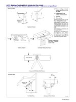
NOTE: The above illustrations are typical examples of cross joint profiles that are in common use for connecting rectangular
sheet metal ducts.
There are no set dimensions for these profiles shown in Figs. 1 1 and 12 provided they are certified under the HVCA testing
scheme DW/TM1 "Acceptance Scheme for new products - Rectangular cross joint classification" and are appropriate to the
duct application. The manufacturer's technical data should be followed with respect to:
Connections to duct wall
Corner treatment
Addition of cleats
Application of sealants
Strength ratings
Application of tie bars
A list of manufacturers and profiles that are covered by current DW/TMI certificate is available from the Ductwork Group
Secretary at HVCA.
21
22
23
(1) A minimum of 2 fixings per side, with a maximum distance from the corner to the first fixing of 50 mm
(2) Except when pierced dimpling is used, one of the other types of fastening must be used at each end in
addition to dimpling
(3) In addition to dimpling, one of the other types of fastening must be used at 450 mm centres, and in all
cases not less than 1 per side
(4) Where manufacturers have specific recommendations, then these shall take precedence over the centres in
the Table above
(5) Mechanically closed rivets are not recommended for fixing external stiffeners to ductwork exceeding
500pa negative.
24