Introduce to sheet metal forming process
Bạn đang xem bản rút gọn của tài liệu. Xem và tải ngay bản đầy đủ của tài liệu tại đây (1.19 MB, 47 trang )
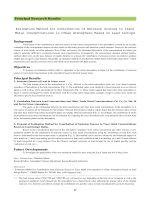
Introduction to sheet metal forming processes
Copyright © 2001 SimTech Simulation et Technologie All rights reserved page1/47
INTRODUCTION TO SHEET METAL
FORMING PROCESSES
The documents and related know-how herein provided by SIMTECH subject to
contractual conditions are to remain confidential. This documentation and related
know-how shall not be disclosed, copied or reproduced by any means, in whole or
in part, without the prior written permission of SIMTECH.
© 1999 SIMTECH. All rights reserved
Product names are mentioned for identification only and may be registered
trademarks.
SIMTECH
37 rue des Acacias, 75017 Paris
FRANCE
Tel: (33) (1) 56 68 80 00
Fax: (33) (1) 56 68 80 06
Introduction to sheet metal forming processes
Copyright © 2001 SimTech Simulation et Technologie All rights reserved page2/47
INTRODUCTION: EVOLUTION OF INDUSTRIAL STAMPING
Back in 1985, the development cycle of a stamped part looked more or less like
this (a sequential series of operations stemming from a single style design):
P
Process Dev.
42 months
Pd t
Product Design
Soft/Hard
tool built
Soft/Hard
tool tryout
STYLE
DESIGN
Product Devpt.
Today, people look at it rather as a sort of funnel, where key decisions are taken
on the basis of different factors and alternative choices.
style
design
proces
product-process
validation
tooling CAM
tryout
production
18 months
Introduction to sheet metal forming processes
Copyright © 2001 SimTech Simulation et Technologie All rights reserved page3/47
OVERVIEW: THE STAMPING SYSTEM AND STAMPING DESIGN
Like all complex system, stamping can be decomposed in hardware and software.
By hardware we mean factors that cannot be changed from one operation to
another. Conversely, by software we mean factors that the operator can change in
order to obtained the desired result : a part with a given quality.
HARDWARE SOFTWARE
Press
Press set-up
Tools Material
Lubrication
The highlighted areas represent the components of the stamping design.
Introduction to sheet metal forming processes
Copyright © 2001 SimTech Simulation et Technologie All rights reserved page4/47
What is a stamping press ?
A stamping press is a machine that houses the stamping tools (tooling) and carries
them around according to the kinematics indicated by the user (process set-up).
The knowledge of the press used for a stamping operation provides us with useful
clues regarding:
• Value and distribution of restraining forces
• Tool deformation caused by stamping forces
• Contact and/or gap between tools and blank
However, we should recall that, at the moment when the die design is carried out,
the press is usually not yet known, so that its characteristics are rather a factor of
noise than a useful information. Therefore, it will be important to have a design that
is robust with respect to the press type.
Introduction to sheet metal forming processes
Copyright © 2001 SimTech Simulation et Technologie All rights reserved page5/47
What is a stamping tool? What is process design?
die
blankholder
punch
blankholder
Run-offs
design area
GLOSSARY:
Design surface
Part as designed to fit in the car (after trimming)
Blankholder
surface
Surfaces that hold the blank before the forming
operation, including the restraining
Production
surface/run-offs
Junction between the two former surfaces,
protecting the design surface and controlling
material flow
Dieface
Run-offs + blankholder
Process design is the ensemble of operations leading from the design geometry to
the dieface.
Introduction to sheet metal forming processes
Copyright © 2001 SimTech Simulation et Technologie All rights reserved page6/47
What is a stamping operation?
A sheet formed part is usually obtained through a number of operation (phases)
final
surface
intermediate
surface
Each operation can be decomposed in several phases. It may be necessary to
model each of them
• Gravity fall
• Holding
• Forming
• Trimming, flanging
• Springback
Most problems in sheet metal forming come from a bad control of holding,
restraining and springback.
Gravity fall
The blank adapts to the blankholder shape
BLANKHOLDER
PUNCH
original flat blank
gravity deformed blank
Holding
The die pushes on the blankholder and squeezes the blank
Introduction to sheet metal forming processes
Copyright © 2001 SimTech Simulation et Technologie All rights reserved page7/47
PUNCH
Holding controls the shape of the blank and the contact between the blank and the
punch.
Forming
The die goes down until it squeezes the blank onto the punch
Introduction to sheet metal forming processes
Copyright © 2001 SimTech Simulation et Technologie All rights reserved page8/47
The forming operation can in turn be divided in two parts:
First the volume of the part is created:
this is mostly controlled by the
production surface and by the
restraining system
Last the geometry details are formed:
this is controlled by the geometry of the
part
Trimming and springback
Plastic deformation leaves some stresses locked through metal thickness. After
the extraction from the tools these stresses are released originating a different
shape than that of the tools.
Springback before trimming is sometimes important for the design of the tools and
robots of the press.
Springback after trimming may change the shape of the part to the point that it is
impossible to assemble.
Introduction to sheet metal forming processes
Copyright © 2001 SimTech Simulation et Technologie All rights reserved page9/47
STAMPING PROCESS DESIGN
Deliverables of process design
Dieface design
Delivered in drawing or, most often
nowadays, CAD format.
Dieface design specifies the geometry
of the dieface for each of the stations
considered.
Cutting pattern
Cutting pattern profile is also delivered in drawing or CAD format. It specifies the
geometry of the punching tool prior to the actual stamping operation.
Production constraints usually force the use of simple cutting patters. In practice,
some basic shapes are used:
rectangle trapeze rectangle w/ cuts rectangle w/ slot
Introduction to sheet metal forming processes
Copyright © 2001 SimTech Simulation et Technologie All rights reserved page10/47
Stamping cycle
Stamping cycle is the description of all the operations leading to the production of
the finished stamped part. A typical stamping cycle includes:
• One or more stamping stations
• One coining station
• One trimming station
• One punching and flanging station
Introduction to sheet metal forming processes
Copyright © 2001 SimTech Simulation et Technologie All rights reserved page11/47
Dieface design
The simplified die addendum: basic geometry feature of the dieface
Although an actual dieface is a rather complicated system of surfaces, some basic
geometry features can be identified. Such basic features can be summarized as
follows :
• Stamping direction : identified on
the basis of minimum undercut,
inertia moment or straightness of
projected characteristic lines.
• Punch radius line : identified after
flange development and protection
• Die entry line : joins the punch line
to the blankholder, with an opening
angle to avoid undercuts
• Blankholder : can be developable
(conical or ruled) or quasi-
developable. Non-developable
blankholders may give rise to
wrinkling problems during the
holding phase.
punch radius
line
Die entry line
stamping direction
blankholder
• Other run-offs components.
Typically, a dieface contains local
elements (sausages) designed to
control punch/blank impact and/or
to stretch locally the material.
Introduction to sheet metal forming processes
Copyright © 2001 SimTech Simulation et Technologie All rights reserved page12/47
How many steps ?
Coining
Flanging
Trimming and springback reduction
Introduction to sheet metal forming processes
Copyright © 2001 SimTech Simulation et Technologie All rights reserved page13/47
MATERIAL DEFORMATION DURING SHEET METAL FORMING
Deformation analysis
Principal strain plane
The analysis of deformation in sheet metal forming is often based on the two
principal membrane strains ε
1
and ε
2
.
Most often, the maximum principal strain ε
1
is positive in a forming operation.
Hence, only half of the strain plane is considered (actually, three quarters).
Deformation pairs relative to different
points of a stamped part are often
plotted on such a half-plane.
This information can be drawn either
from FE simulation or from
experimental analysis (grids).
The analysis of such deformation plots
gives useful insights into the
mechanics of a forming operation.
drawing expansion
ε
1
ε
2
The deformation plot lends itself to
several interesting considerations.
Lines departing from the origin are
equivalent to constant strain mode
ε
ε
1
2
.
ε
1
ε
2
pure
ex
p
ansion
plane
strain
plane
stress
pure
shea
r
Introduction to sheet metal forming processes
Copyright © 2001 SimTech Simulation et Technologie All rights reserved page14/47
We can identify:
A line of pure expansion, where
ε
ε
21
=
A line of plane strain, where
0
1
=
ε
A line of plane stress, where
0
2
=
σ
A line of pure shear, where
ε
ε
21
−=
Further, based on the principle of
conservation of volume, lines at 45°
.)(
321
cst
ε
ε
ε
−=+
represent the loci of constant
thickness.
For each of these lines, the thinning ∆t,
ε
1
ε
2
relative to the initial thickness t
0
can be computed from basic rules of mechanics :
()
e
t
t
εε
21
1
0
+−
−=
∆
Grid analysis
Introduction to sheet metal forming processes
Copyright © 2001 SimTech Simulation et Technologie All rights reserved page15/47
Modes of deformation
In this chapter, we address the topic of material deformation, following the jargon
of die engineers rather than of the mechanical engineers. The reader is
encouraged to compare the deformation modes described here and in the
preceding chapter.
Definition
In sheet metal forming practice, we distinguish five basic modes of deformation:
• STRETCHING: The material is expanded in
both directions. This mode of deformation is
found mostly on smooth bottoms of shallow
parts and in hydroforming processes.
• DRAWING: This mode is typical the
material flow from the flange towards the
inner part of the die.
• BENDING/UNBENDING: This is a cyclic
deformation (most often associated with
plane strain). It is found on the die entry line
as well as in drawbeads.
• STRETCH-AND-BEND: This mode is
associated to flanging operations for which
the bending line is concave.
l 1
l 0
• COMPRESSION-AND-BEND: This mode is
associated to flanging operations for which
the bending line is convex.
l 1
l 0
Introduction to sheet metal forming processes
Copyright © 2001 SimTech Simulation et Technologie All rights reserved page16/47
Correlation between deformation modes and geometry
Remember:
The designer thinks in
term of geometrical
features: wall, angel,
flanges, etc
wall
angle
wall
flange
Upper surface
but the die engineer
sees the part as a
collection of areas, often
quite well separated,
where different
deformation modes
occur.
baxial
expansion
expansion
bending/unbending
bending/unbending
drawing
stretch-bend
compression-bend
Introduction to sheet metal forming processes
Copyright © 2001 SimTech Simulation et Technologie All rights reserved page17/47
FACTORS CONTROLLING DEFORMATION
In the following, several factors controlling the stamping operation are analyzed.
However, it should be pointed out that a hierarchy exists among the different
factors, which is partially echoed by the traditional product development workflow.
In order of importance, we can thus identify:
1. Part geometry
2. Dieface (active tooling surface) geometry
3. Material rheological properties
4. Lubrication and restraining systems
Introduction to sheet metal forming processes
Copyright © 2001 SimTech Simulation et Technologie All rights reserved page18/47
Part geometry
In order to appreciate the foremost importance of the part geometry with respect to
all other factors influencing sheet metal forming, we should recall that a sheet
metal forming operation can always be,
from the conceptual point of view,
divided in two stages:
• A first stage where the volume of the
part is generated
• A second stage where the
geometrical details are formed
(reverse drawing)
In the first stage, deformation and
material flow are mostly controlled by
run-offs (die addendum or dieface).
In the second stage, however, most of the deformation is due to local reverse
drawing or stretching, on which die addendum has little or no impact. Most
"unfeasible" parts present defects produced in this stage. The identification and
the correction of these problems, which can be achieved through the early use of
numerical simulation, lead to anticipate the modifications, which can be made at a
much lower cost.
The rear wall of the IVECO cabin
represents a very interesting example.
Here, all the problems encountered at
the die try-out stage have been
identified on the base only of the part
as designed analysis. On the other
hand, defects appear with the same
calculation (folds on the edge of the
part) which would have disappeared as
soon as a run-off and a blankholder
surface were added.
Introduction to sheet metal forming processes
Copyright © 2001 SimTech Simulation et Technologie All rights reserved page19/47
Tool geometry
If part geometry controls mainly
deformation in reverse-drawing areas,
relatively far from the die edge, it can
be expected that tool geometry be
mostly important in deep-drawn areas
around the part boundary. As it always
happens with complicated problems,
this statement is dangerous to
generalize but can be found true in
many occasion.
For the RENAULT LAGUNA's engine
support, the first proposition of
blankholder (flat surface) yields very
large strains in an area where
subsequent flanging produces rupture.
The modification of the dieface (curved
blankholder surface) allows for a more
even drawing depth along the part
contour. Part thinning is halved (from
20% to 10%), though using less metal
sheet, thanks to a removal of an
excessive run-off.
At last, run-offs around the problem
area can also be improved, via the use of evolutionary radii instead of constant
radii. This leads to a further decrease in thinning (down to 8% for the case
studied).
Other examples of run-offs geometry are die entry radius
INSERER DISCUSSION SUR COPPA DIEX
Introduction to sheet metal forming processes
Copyright © 2001 SimTech Simulation et Technologie All rights reserved page20/47
Cutting pattern
The profile of the initial blank has a great influence on the material flow, especially
for deep drawn parts.
Typically, cutting corner eases the material flow in corner areas, with a significant
reduction of thinning and a corresponding increase of wrinkles or wrinkle risk.
The identification of the optimal cutting pattern may be useful in process design.
It is often assumed that the optimal cutting pattern is an offset of the die entry line.
Actually, it also depends on the different section lengths of the stamped part.
Inverse simulation codes enable the user to identify optimal cutting pattern
accurately.
Introduction to sheet metal forming processes
Copyright © 2001 SimTech Simulation et Technologie All rights reserved page21/47
Material mechanical properties
Ductility (strain hardening)
A basic engineering notion is that material behavior in the first stages of
deformation is approximately elastic, i.e. the material returns to its initial state after
the external cause (force) is removed.
Further deformation will be at least partially permanent. For metals, this pattern of
permanent deformation is called plasticity.
After the onset of plastic deformation (yield point) the stress generated in the
material continues to grow (even though at a slower pace) as deformation
increases. This phenomenon is called
strain hardening. The ability of the material
to deform plastically before failure is called
ductility. The two properties are tied to
each other, as it will be shown later.
The standard description of ductile behavior is the tensile test:
Experimental data:
(tensile test, engineering stress and
strain)
σ
y
= yield stress
R
m
= ultimate strength
%
A = elongation to failure
Engineering strain e
Engineering stress s
R
m
σ
y
A
%
The tensile test identifies three thresholds:
• Passage from the elastic phase to the plastic phase:
σ
y
. This is not
interesting for sheet metal forming simulation.
• Necking:
R
m
. This phase of the deformation is well known and reasonably
well modeled.
• Rupture: . Little is known of material behavior between necking and rupture.
In particular, SMF simulation codes simply extrapolate pre-necking behavior.
Good stamping practice suggest remaining below necking level, so that surface
defects (for outer panels) or excessive thinning (for structural parts) are avoided.
However, in many cases the actual stamped part is formed way beyond necking
point (e.g. tanks, sinks and other deep drawn parts).
Introduction to sheet metal forming processes
Copyright © 2001 SimTech Simulation et Technologie All rights reserved page22/47
Material strain hardening is usually modeled into account via the Krupkovsky-Swift
law, linking the equivalent stress in the Hill-Von Mises sense to the equivalent
plastic deformation.
(
)
σ
εε
=+k
p
n
0
where k,
ε
p
and n are material constants defined below.
Remark :
It is important to stress again that the Krupkovsky-Swift law is valid only
below necking point.
The above defined Krupkovsky-Swift law is obtained in practice by modifying the
better-known Hollomon law (valid for
ε
p
>> 0) :
σ
ε
= k
p
n
so that the value of stress at or around zero coincides with the yield stress.
Remark :
• High strain hardening coefficients are beneficial for the forming of stretched
parts
Material characteristics required for the definition of the Krupkovsky-Swift law can
be deduced from the results of a standard tensile test using the following
procedure:
Experimental data:
(tensile test, engineering stress and
strain)
σ
y
= yield stress
R
m
= ultimate strength
Engineering strain e
Engineering stress s
R
m
σ
y
Introduction to sheet metal forming processes
Copyright © 2001 SimTech Simulation et Technologie All rights reserved page23/47
Krupkovsky law :
σ
= k(
ε
0
+
ε
)
n
Useful formulas:
s =
σ
1 + e
⇔
σ
= (1 + e)s
ε
= ln(1 + e) ⇔ e = exp(
ε
) −1
t
r
u
e
s
t
r
e
s
True strain
ε
σ
n = strain hardening coefficient
is easily computed by linear
regression on a log/log plot.
Remark:
Estimation of n is highly dependent
on the deformation window
considered.
log
ε
log
σ
1) Computation of
k
:
for
ε
>>
ε
0
σ
= k(
ε
0
+
ε
)
n
≈ k
ε
n
With some algebra, we can show that the engineering stress la
R
m
is reached for
an elongation
e = exp(n) −1, i.e. that the true strain corresponding to necking is
equal to the hardening coefficient n. The true stress corresponding to ultimate
strength
R
m
is therefore:
σ
s=R
m
= (1 + e)R
m
= exp(n)R
m
⇒ exp(n)R
m
= kn
n
⇒ k = R
m
e
n
n
2) Computation of
ε
0
We can impose that the strain hardening curve passes through the yielding point
when plastic deformation is equal to zero:
σ
e=0
=
σ
y
⇒ k
ε
0
=
σ
y
⇒
ε
0
=
σ
y
k
n
Introduction to sheet metal forming processes
Copyright © 2001 SimTech Simulation et Technologie All rights reserved page24/47
Behavior under load cycles (isotropic vs. cinematic hardening)
Material resistance (yield and ultimate
strength) may be significantly different
after a prior deformation.
Two idealized models are used:
• Isotropic hardening. If loading is
reversed after a first monotonic
loading (up to σ
1
), the second
yielding point is symmetrical with
respect to the maximum stress in
monotonic loading (-
σ
1
).
• Kinematic hardening. If loading is
reversed after a first monotonic
loading (up to
σ
1
), the material
shows always the same apparent
resistance to yielding, so that the
yielding point for the reverse load is
σ
σ
σ
01
2
y
−=
σyo
σ1
σ1
σ2
σ
σ
2
ε
monotonic
load
cyclic
load
EEE
isotropic hardening
σ
ε
monotoni
c
loading
cyclic loading
E
E
σ
1
2σ
10
cinematic hardening
Anisotropy
While strain hardening and ductility are general characteristic of metallic materials,
anisotropy (at least, the kind that we consider here) is a typical feature of cold
rolled steel sheets.
Introduction to sheet metal forming processes
Copyright © 2001 SimTech Simulation et Technologie All rights reserved page25/47
During rolling operation, two
phenomena happen in the material:
• The surface is hardened, leading
to a greater stiffness and
resistance in the thickness
direction.
• The fibers are oriented in the
rolling direction, changing
directional response in the sheet
plane.
hardened
surface area
Material anisotropy for metal blanks is quantified using the Lankford, ratio,
measured during the tensile test.
Lankford ratio r
α
r
α
=
d
ε
α+π/2
dε
t
=
d
ε
yy
dε
zz
≅
ε
yy
ε
zz
α
x, y, z local axis syste
m
1, 2, 3 global axis system
x
y
z, 3
1
2
ROLLING DIRECTION
Reference frame definition
Remark:
• High Lankford ratios reduce the thinning of the sheet during stamping
processes.
During a uniaxial tension test, specimens cut at different angles α to the rolling
direction show different yield stresses and Lankford ratios.
Such differences are also found in the yield stresses measured at different
orientations.