1 8,2 2 valve clearance specs
Bạn đang xem bản rút gọn của tài liệu. Xem và tải ngay bản đầy đủ của tài liệu tại đây (218.93 KB, 26 trang )
1.8L & 2.2L 4-CYL
Article Text
1998 Subaru Impreza
ARTICLE BEGINNING
1995-98 ENGINES
Subaru - 1.8L & 2.2L 4-Cylinder
1995-97:
1995-98:
Impreza (1.8L)
Impreza (2.2L), Legacy (2.2L)
* PLEASE READ THIS FIRST *
NOTE:
For engine repair procedures not covered in this article,
see ENGINE OVERHAUL PROCEDURES - GENERAL INFORMATION article
in the GENERAL INFORMATION section.
ENGINE IDENTIFICATION
Engine can be identified by sixth character of Vehicle
Identification Number (VIN). The VIN is stamped on a metal plate
located on right front side of firewall. Engine identification number
is stamped on a machined pad on left rear of cylinder block.
ENGINE IDENTIFICATION CODE
ÄÄÄÄÄÄÄÄÄÄÄÄÄÄÄÄÄÄÄÄÄÄÄÄÄÄÄÄÄÄÄÄÄÄÄÄÄÄÄÄÄÄÄÄÄÄÄÄÄÄÄÄÄÄÄÄÄÄÄÄ
Application
VIN Code
1995
1.8L .................................................
2.2L .................................................
1996
1.8L
AWD ................................................
FWD ................................................
2.2L
AWD ................................................
FWD ................................................
1997
1.8L .................................................
2.2L
AWD ................................................
FWD ................................................
1998
2.2L
AWD ................................................
FWD ................................................
2
6
2
1
4
3
2
4
3
4
3
ÄÄÄÄÄÄÄÄÄÄÄÄÄÄÄÄÄÄÄÄÄÄÄÄÄÄÄÄÄÄÄÄÄÄÄÄÄÄÄÄÄÄÄÄÄÄÄÄÄÄÄÄÄÄÄÄÄÄÄÄ
ADJUSTMENTS
VALVE CLEARANCE ADJUSTMENT
NOTE:
Engines on 1995-96 models are equipped with hydraulic lash
adjusters. Valve adjustment is not required.
NOTE:
Perform valve adjustment when engine is cold.
1997-98 Models
Disconnect battery ground cable. Remove connector from mass
airflow sensor. Remove air intake duct and upper air cleaner cover as
a unit. Remove air filter. Disconnect washer fluid pump wire connector
and hose. Remove washer fluid tank. Remove right side timing belt
cover. Remove spark plug wires.
2) Raise and support vehicle. Remove undercovers. Disconnect
PCV hoses and remove valve covers. Set No. 1 cylinder to TDC of
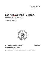
compression stroke. Arrow mark on right-side camshaft sprocket should
be pointing up. See Fig. 1. Using feeler gauge, measure No. 1 cylinder
valve clearance. Adjust as needed. Tighten lock nut to 78-95 INCH lbs.
(9-11 N.m). See VALVE CLEARANCE SPECIFICATION.
3) Rotate crankshaft 180 degrees clockwise (camshaft turns 90
degrees) so the next cylinder in firing order is at TDC, and
check/adjust valve clearance for that cylinder. See Fig. 1. Repeat
procedure until all valves have been adjusted.
Fig. 1: Identifying Camshaft/Cylinder Top Dead Center Positions
Courtesy of Subaru of America, Inc.
VALVE CLEARANCE SPECIFICATION
ÄÄÄÄÄÄÄÄÄÄÄÄÄÄÄÄÄÄÄÄÄÄÄÄÄÄÄÄÄÄÄÄÄÄÄÄÄÄÄÄÄÄÄÄÄÄÄÄÄÄÄÄÄÄÄÄÄÄÄÄ
epair
Information Company, LLC
Application
Clearance In. (mm)
Intake .............................
Exhaust ............................
.0070-.0087 (.18-.22)
.0091-.0106 (.23-.27)
ÄÄÄÄÄÄÄÄÄÄÄÄÄÄÄÄÄÄÄÄÄÄÄÄÄÄÄÄÄÄÄÄÄÄÄÄÄÄÄÄÄÄÄÄÄÄÄÄÄÄÄÄÄÄÄÄÄÄÄÄ
REMOVAL & INSTALLATION
* PLEASE READ THIS FIRST *
NOTE:
For reassembly reference, label all electrical connectors,
vacuum hoses and fuel lines before removal. Also place mating
marks on engine hood and other major assemblies before
removal.
FUEL PRESSURE RELEASE
1995-97 Models
Disconnect fuel pump wiring connector located under rear
seat. Start engine and let idle until it stalls. Crank engine for an
additional 5 seconds. Turn ignition off.
1998 Models
Disconnect fuel pump relay connector located under left side
of dash. Start engine and run until it stalls. Crank engine for an
additional 5 seconds. Turn ignition off.
ENGINE
NOTE:
Transaxle remains in vehicle with engine removal.
Removal
1) Release fuel pressure. See FUEL PRESSURE RELEASE. Drain
cooling system. Disconnect battery and remove from vehicle. Remove air
intake duct/upper air cleaner cover assembly. Disconnect radiator and
heater hoses. Disconnect A/T cooler lines (if equipped). Remove
radiator.
2) Identify, mark and disconnect electrical connectors,
vacuum hoses and fuel lines that interfere with engine removal.
Discharge A/C system using approved refrigerant recovery/recycling
equipment. Disconnect accelerator cable, cruise control cable (if
equipped) and clutch cable/hill holder cable at clutch release fork
(M/T).
3) Remove accessory drive belts. Remove power steering pump
with hoses attached and set aside. Remove hoses from A/C compressor
and set aside. Raise and support vehicle. Remove front exhaust pipe.
Disconnect engine mount from front crossmember. Remove nuts attaching
lower engine to transaxle.
4) Remove all brackets interfering with engine removal.
Remove flywheel access cover. Disconnect bolts securing drive plate to
torque converter (A/T). Support engine using hoist. Support transaxle
using floor jack. Remove bolts attaching upper side of engine to
transmission. Remove engine.
Installation
To install, reverse removal procedure. Tighten bolts and nuts
to specification. See TORQUE SPECIFICATIONS. Adjust all control
cables. Check all fluid levels.
INTAKE MANIFOLD
Removal & Installation
1) Release fuel pressure. See FUEL PRESSURE RELEASE. Remove
"V" belt. Disconnect negative battery cable. Remove air intake
duct/upper air cleaner cover assembly. Disconnect throttle cable.
Disconnect cruise control cable (if equipped). Remove power steering
belt. Remove power steering pump with hoses attached and set aside.
2) Disconnect PCV and ventilation hoses. Disconnect spark
plug wires. Disconnect coolant hoses and air by-pass hose from
throttle body. Disconnect electrical connectors and vacuum hoses
interfering with intake manifold removal.
3) Remove EGR pipe. Disconnect fuel hoses from pipes. Remove
intake manifold-to-cylinder head bolts. Remove intake manifold. To
install, reverse removal procedure. Use NEW gaskets. Tighten bolts to
specification. See TORQUE SPECIFICATIONS.
EXHAUST MANIFOLD
NOTE:
Exhaust manifold is integral with cylinder head.
CYLINDER HEAD
Removal
Release fuel pressure. See FUEL PRESSURE RELEASE. Drain
engine coolant. Remove timing belt and camshaft sprocket. See TIMING
BELT. Remove intake manifold and exhaust pipe. See INTAKE MANIFOLD.
Remove cylinder head bolts in reverse order of tightening sequence.
See Fig. 2. Remove cylinder head and gasket.
Inspection
Check cylinder head warpage and height. Resurface head if
warpage exceeds specification. See CYLINDER HEAD table under
ENGINE SPECIFICATIONS. Replace cylinder head if height is not within
specification.
Installation
Ensure mating surfaces are clean and dry. Install head
gasket. Coat head bolt threads with oil. Tighten bolts to
specification in sequence. See Fig. 2. See TORQUE SPECIFICATIONS. To
complete installation, reverse removal procedure.
Fig. 2: Cylinder Head Bolt Tightening Sequence
Courtesy of Subaru of America, Inc.
TIMING BELT
Removal
1) Remove generator drive belt. Remove A/C belt and
tensioner, if equipped. Remove crankshaft pulley. If engine is removed
from vehicle, crankshaft can be held using Crankshaft Pulley Wrench
(499977000).
Fig. 3: Identifying Crankshaft Pulley & Timing Belt Covers
Courtesy of Subaru of America, Inc.
2) Remove left, right and front timing belt covers. See
Fig. 3. If timing belt is to be reused, mark belt to indicate original
direction of rotation before removal, if original marks are worn away
or faded. Also mark belt to indicate belt-to-sprocket alignment, if
original marks are worn away or faded. See Fig. 4.
Fig. 4: Identifying Timing Belt Components
Courtesy of Subaru of America, Inc.
3) To mark belt, turn crankshaft with Crankshaft Socket
(499987500) to align marks on crankshaft sprocket and left and right
camshaft sprockets with notches on timing belt cover and engine block.
See Fig. 5.
Fig. 5: Aligning Crankshaft Sprocket & Left & Right Camshaft
Sprocket Marks
Courtesy of Subaru of America, Inc.
4) Use White paint to mark direction of rotation and to mark
timing belt in relation to sprocket timing marks. When marks are
properly aligned, 44 teeth should be on right side of crankshaft
sprocket and 40.5 teeth should be on left side of crankshaft sprocket.
See Fig. 6.
Fig. 6: Aligning Timing Belt Before Removal (Impreza)
Courtesy of Subaru of America, Inc.
5) Loosen tensioner adjuster mounting bolts. Remove belt
idler, and belt idler No. 2. Remove timing belt. Remove upper belt
idler. Remove belt tensioner and spacer. Remove belt tensioner
adjuster. See Fig. 7
Fig. 7: Removing Timing Belt Tensioner Components
Courtesy of Subaru of America, Inc.
Inspection
1) Inspect timing belt for wear on rounded edges of drive
teeth. Inspect belt for signs of oil contamination. Replace belt if it
is damaged or contaminated. Inspect belt tensioner adjuster oil seals
for leaks. Inspect rod ends for abnormal wear and scratches. Timing
belt bend radius must be greater than 2.36" (60.0 mm). See Fig. 8.
2) Slight trace of oil at rod oil seal does not indicate a
problem. While holding tensioner with both hands, push rod section
against floor or wall using a force of 33-110 lbs. (15-50 kg) to
ensure rod section does not move.
3) If rod section moves, replace tensioner adjuster with a
NEW one. Measure extension of rod beyond body. Rod extension should be
.606-.646" (15.40-16.40 mm). Replace belt tensioner adjuster if
extension of rod is not as specified. Inspect belt tensioner and belt
adjuster rod mating surface. Check spacer and tensioner bushing for
wear.
Fig. 8: Measuring Timing Belt Bend Radius
Courtesy of Subaru of America, Inc.
Installation
CAUTION: DO NOT allow press pressure to exceed 2205 lbs. (992 kg).
DO NOT release pressure until stopper pin is completely
installed.
1) Ensure timing marks are aligned. Using a press, push rod
into body until holes in belt tensioner adjuster rod and adjuster body
are aligned. Install .059" (1.50 mm) diameter stopper pin into holes
in adjuster body and rod. See Fig. 9.
2) Install belt tensioner adjuster, and temporarily tighten
mounting bolts while tensioner adjuster is pushed completely to the
right. Install belt tensioner and spacer. Install upper belt idler.
Ensure crankshaft and camshaft alignment marks are aligned. See Fig. 5
.
3) Install timing belt, being careful not to move sprockets.
Ensure rotation direction of belt is correct and that all alignment
marks are aligned when belt is installed. See Fig. 6. Install belt
idler No. 2 and belt idler. Loosen tensioner adjuster mounting bolts
and push tensioner adjuster completely left. Tighten tensioner
adjuster mounting bolts.
4) Ensure marks on timing belt and sprockets align. See
Fig. 6. Remove stopper pin from tensioner adjuster. Install timing
belt covers, crankshaft pulley and generator drive belt. Install A/C
belt and tensioner, if equipped. Remove rocker covers, and ensure
valve lash adjuster does not contain air.
Fig. 9: Installing Tension Adjuster Rod Stopper Pin
Courtesy of Subaru of America, Inc.
ROCKER ARM ASSEMBLY
Removal & Installation
1) Disconnect PCV hose, and remove rocker cover. Loosen, but
DO NOT remove, bolt No. 1. See Fig. 10. Remove rocker bolts No. 2-4 in
order. Remove bolts No. 5-8. Remove rocker arm assembly.
2) On models with hydraulic lash adjusters, ensure rocker arm
assembly air vent remains facing upward or submerge rocker arm
assembly in clean engine oil.
3) To install, reverse removal procedure. DO NOT allow rocker
arm assembly to gouge dowel/alignment pins. Tighten bolts in reverse
order of loosening sequence to specification. See Fig. 10. See
TORQUE SPECIFICATIONS.
Fig. 10: Rocker Bolt Loosening Sequence
Courtesy of Subaru of America, Inc.
CAMSHAFT
Removal
Remove timing belt, valve covers and camshaft sprockets. See
TIMING BELT.
NOTE:
The following procedure is for removal of left camshaft.
Procedure for right camshaft is similar.
Remove rocker arm assembly. See ROCKER ARM ASSEMBLY. Remove
camshaft position sensor. Remove valve lash adjusters and submerge in
clean engine oil (if equipped). Remove oil dipstick tube mounting
bolt. Remove camshaft support and "O" ring. Remove camshaft. Remove
oil seals only if necessary.
Inspection
1) Place camshaft in "V" blocks. Measure bend. Bend limit is
.001" (.025 mm). Check cam face condition. Remove minor burrs by
grinding using oil stone. Check cam height and journal for damage or
wear.
2) Measure outside diameter of camshaft journal and inside
diameter of cylinder head journal to determine camshaft oil clearance.
If clearance is not within specification, replace camshaft or cylinder
head as necessary. See CAMSHAFT under ENGINE SPECIFICATIONS.
3) Measure camshaft end play. If end play is not within
specification, replace camshaft support.
Installation
1) Apply a coat of clean engine oil to camshaft journals.
Install camshaft. Lubricate "O" ring and Install to camshaft support.
Install camshaft support.
2) Apply grease to oil seal lips. Using Oil Seal Guide
(499597000) and Oil Seal Installer (499587100), install oil seal on
camshaft support. To complete installation, install rocker cover,
timing belt, camshaft sprockets and related parts. Perform necessary
adjustments.
OIL PAN
Removal & Installation
Drain oil. Remove oil pan bolts. Remove oil pan and gasket.
To install, reverse removal procedure using NEW gasket. Tighten bolts
to specification. See TORQUE SPECIFICATIONS.
WATER PUMP
Removal
Repair Information
1)
Company,
Disconnect
LLC
negative battery cable. Drain engine coolant.
Disconnect radiator hose from water pump. Remove electric cooling fan.
2) Remove all accessory drive belts. Remove timing belt. See
TIMING BELT. Remove belt tension adjuster and camshaft position
sensor. Using Camshaft Sprocket Wrench (499207100), remove left-side
camshaft pulley.
3) Remove left-side rear timing belt cover. Remove tensioner
bracket. Disconnect heater hose from water pump. Remove water pump.
Installation
To install, reverse removal procedure using a NEW gasket.
Tighten bolts to specification in sequence. See Fig. 11. See
TORQUE SPECIFICATIONS.
Fig. 11: Water Pump Bolt Tightening Sequence
Courtesy of Subaru of America, Inc.
OVERHAUL
CYLINDER HEAD
Valve Springs
Measure free length of valve springs. Check spring tension at
specified height. Replace springs if free length or tension is not
within specification. Check valve spring for squareness. See
VALVES & VALVE SPRINGS under ENGINE SPECIFICATIONS.
Valve Stem Oil Seals
With valves removed, remove oil seals from cylinder head.
Intake valve stem seal is Black with White or Silver spring. Exhaust
valve stem seal is Brown with White or Silver spring. Coat seals with
oil. Using Valve Stem Oil Seal Guide (498857100), install valve stem
oil seal.
Valve Guides
1) Check clearance between valve guide and stem. Clearance is
checked by measuring outside diameter of valve stem and inside
diameter of valve guide using an outside and inside micrometer.
2) If clearance is not within specification, replace valve
guide. See CYLINDER HEAD under ENGINE SPECIFICATIONS. To replace valve
guide, position cylinder head with combustion chamber facing upward.
Insert Valve Guide Remover (499767200) into valve guide and press down
to remove valve guide.
3) Invert cylinder head and place Valve Guide Adjuster
(499767000) in position shown. See Fig. 12. Coat new valve guide with
engine oil. Insert Valve Guide Remover (499767200) into valve guide.
Press in until valve guide upper end is flush with upper surface of
valve guide adjuster.
4) Check valve guide protrusion. Valve guide protrusion
should be .69-.71" (17.5-18.0 mm). Ream inside of valve guide using
Valve Guide Reamer (499767400). Ensure all chips and metal particles
are cleaned from valve guide. Recheck contact between valve and valve
seat after replacing valve guide.
Fig. 12: Positioning Valve Guide Adjuster On Cylinder Head
Courtesy of Subaru of America, Inc.
Valve Seat
Inspect intake and exhaust valve seats. Correct contact
surfaces with valve seat cutter if surfaces are defective or when
valve guides are replaced. See CYLINDER HEAD under ENGINE
SPECIFICATIONS.
Valves
Measure valve stem diameter and valve margin. Replace valves
if they are not within specification. See VALVES & VALVE SPRINGS under
ENGINE SPECIFICATIONS. Recheck valve margin after grinding valves.
epair Information Company, LLC
VALVE TRAIN
Rocker Arm Shaft Assembly
Check oil clearance between valve rocker arm and shaft.
Clearance should be .0008-.0021" (.020-.054 mm) with a limit of .004"
(.10 mm). Replace valve rocker or shaft if clearance is not as
specified.
Lash Adjuster Bleeding
1) Dip valve lash adjuster in engine oil. Push check ball in
using .08" (2 mm) diameter rod. With check ball pushed in, manually
move plunger up and down at one-second intervals until air bubbles
disappear.
2) After air bubbles disappear, remove bar and quickly push
plunger in to ensure it is locked. If plunger does not lock properly,
replace valve lash adjuster. Always leave valve lash adjuster
submerged in engine oil until it is ready for installation.
CYLINDER BLOCK ASSEMBLY
Cylinder Block Disassembly
1) Remove piston pin service hole cover and plugs. Rotate
crankshaft until No. 1 and 2 pistons are at BDC. Remove piston pin
circlips from No. 1 and 2 pistons through service hole.
2) Using Piston Pin Remover (499097500), remove piston pins.
Rotate crankshaft until No. 3 and 4 pistons are at BDC. Remove
circlips and piston pins.
3) Set up cylinder block so cylinders No. 1 and 3 are on
upper side. Remove cylinder block connecting bolts. Separate left and
right cylinder blocks. DO NOT allow connecting rods to fall and damage
block.
4) Remove rear oil seal. Remove crankshaft together with
connecting rods. Remove crankshaft bearings from cylinder block using
hammer handle. Ensure bearings are marked for proper location.
5) Drive out each piston from cylinder block. Note piston
position and location. Remove connecting rod caps. Remove connecting
rod bearings. Note connecting rod cap and bearing locations.
6) Remove piston rings and oil ring. Mark rings for proper
order/location. Remove remaining circlip from piston.
Piston & Rod Assembly
1) Inspect pistons and pins for cracks or damage. Measure
piston diameter at a 90-degree angle to piston pin, 1.575" (40.00 mm)
from top of piston. See PISTONS, PINS & RINGS under ENGINE
SPECIFICATIONS. Replace piston if defective.
2) Ensure piston-to-cylinder clearance is within
specification. Ensure ring gap and side clearance are within
Repair Information Company, LLC
specifications. Ensure piston pin can be inserted in piston with thumb
pressure at 68øF (20øC). See PISTONS, PINS & RINGS under ENGINE
SPECIFICATIONS.
3) Inspect connecting rod thrust surfaces at both ends.
Replace connecting rod if large or small end thrust surface is
damaged. Measure connecting rod bend and twist. Replace connecting rod
if bend or twist exceeds specification. See CONNECTING RODS under
ENGINE SPECIFICATIONS.
4) Inspect connecting rod small end bushing. Measure piston
pin-to-rod clearance. Replace connecting rod bushing if clearance
exceeds specification. See PISTONS, PINS & RINGS under ENGINE
SPECIFICATIONS.
5) Install connecting rod with bearing onto crankshaft.
Measure side clearance. Replace connecting rod if clearance exceeds
specification. See CONNECTING RODS under ENGINE SPECIFICATIONS.
6) Measure connecting rod bearing oil clearance using
Plastigage. Replace bearing if oil clearance exceeds specification.
See CRANKSHAFT, MAIN & CONNECTING ROD BEARINGS under ENGINE
SPECIFICATIONS.
Crankshaft & Main Bearings
1) Inspect crankshaft for cracks. Measure crankshaft runout
at center journal. Measure out-of-round and taper at each journal. See
CRANKSHAFT, MAIN & CONNECTING ROD BEARINGS under ENGINE
SPECIFICATIONS. Grind crankshaft and replace bearing if out-of-round
or taper exceeds specification.
2) Install main bearings in cylinder block. Install
crankshaft in left side of cylinder block. Using feeler gauge, measure
crankshaft end play at center journal. Replace center bearing if end
play exceeds specified service limit.
3) Install right side cylinder block. Measure oil clearance
at each bearing using Plastigage. See
CRANKSHAFT, MAIN & CONNECTING ROD BEARINGS under ENGINE
SPECIFICATIONS. Grind crankshaft and replace bearing if oil clearance
exceeds service limit.
Cylinder Block
Inspect cylinder block for cracks or damage. Measure warpage
at deck surface. Surface cylinder block if warpage exceeds .002" (.05
mm). Cylinder bore size marks are stamped on front upper surface of
block. See Fig. 13. Measure cylinder bore diameter 0.39" (10.0 mm), 1.
77" (80.0 mm), 3.15" (80.0 mm) and 4.53" (115.0 mm) from deck surface.
See CYLINDER BLOCK under ENGINE SPECIFICATIONS. Rebore cylinder if
diameter, taper or out-of-round exceeds service limit.
Fig. 13: Identifying Cylinder Bore Size Marks
Courtesy of Subaru of America, Inc.
Crankshaft & Connecting Rod Installation
1) Lubricate and install bearings in connecting rod and
connecting rod caps. Install connecting rod in proper crankshaft
journal location, with identification mark toward front of crankshaft
and matching numbers aligned.
2) Use NEW connecting rod nuts. Apply oil to connecting rod
bolt threads and tighten nuts to specification. See
TORQUE SPECIFICATIONS. Lubricate and install main bearings in cylinder
block. Install crankshaft in left side of cylinder block.
3) Apply Three Bond 1215 or equivalent to cylinder block
mating surface. Install right side of cylinder block. Tighten 10 mm
bolts in sequence to specification. Tighten 6 mm and 8 mm bolts in
sequence to specification. See Fig. 14. See TORQUE SPECIFICATIONS.
epair Information Company, LLC
4) Install rear oil seal using Oil Seal Guide (499597100) and
Oil Seal Installer (499587200).
Fig. 14: Cylinder Block Bolt Tightening Sequence
Courtesy of Subaru of America, Inc.
Piston & Piston Pin Installation
1) Install rings on piston with "R" mark toward top of
piston. Properly space ring end gaps on piston. See Fig. 15. Ensure
ring gaps are not in piston skirt area. Install one circlip in piston.
2) Rotate crankshaft so that connecting rods for pistons to
be installed are at BDC. Lubricate piston, rings and cylinder bore
with engine oil. Ensure identification mark on piston faces front of
engine. Install piston into cylinder bore.
3) Coat Piston Pin Guide (499017100) with engine oil. Insert
guide into service hole to align piston pin hole with connecting rod
small end. Coat piston pin with engine oil. Insert piston pin into
piston and connecting rod through service hole. Install remaining
circlip. Install service hole plug and NEW gasket.
air Information Company, LLC
Fig. 15: Positioning Piston Ring Gaps
Courtesy of Subaru of America, Inc.
ENGINE OILING
ENGINE LUBRICATION SYSTEM
Oil pressure is provided by a trochoid-type pump driven by
timing belt. Pressure relief valve is located in oil pump body.
Crankcase Capacity
Crankcase capacity is 5.0 qts. (4.7L) with filter
replacement.
Oil Pressure
With engine at normal operating temperature, pressure should
be at least 14 psi (1.0 kg/cmý) at 600 RPM and at least 43 psi (3.0
kg/cmý) at 5000 RPM.
OIL PUMP
Removal
Disconnect negative battery cable. Drain engine oil. Remove
timing belt covers and timing belt. See TIMING BELT under REMOVAL &
INSTALLATION. Remove belt tensioner bracket. Remove left camshaft
sprocket. Remove water pump. Remove oil pump assembly and gasket.
Disassembly & Inspection
1) Disassemble pump. See Fig. 16. Measure tip clearance of
epair
Information
Company,
rotors.
See
OILLLC
PUMP SPECIFICATIONS. If clearance is not as specified,
replace rotors as a matched set.
Fig. 16: Identifying Oil Pump Components
Courtesy of Subaru of America, Inc.
OIL PUMP SPECIFICATIONS
ÄÄÄÄÄÄÄÄÄÄÄÄÄÄÄÄÄÄÄÄÄÄÄÄÄÄÄÄÄÄÄÄÄÄÄÄÄÄÄÄÄÄÄÄÄÄÄÄÄÄÄÄÄÄÄÄÄÄÄÄÄÄÄÄÄÄÄÄÄÄ
Application
In. (mm)
Inner Rotor-To-Pump Cover Side
Clearance ................................. .0008-.0028 (.020-.070)
Inner Rotor Tip-To-Outer Rotor
Clearance ............................. (1) .0016-.0055 (.040-.140)
Outer Rotor-To-Case Clearance .............. (2) .004-.007 (.10-.18)
Relief Valve Spring (3)
Free Length .......................................... 2.83 (71.8)
Installed Length ..................................... 2.15 (54.7)
(1) - Service limit is .007" (.18 mm).
(2) - Service limit is .008" (.20 mm).
(3) - Relief valve spring installed load is 17.33 lbs. (7.86
kg)
ÄÄÄÄÄÄÄÄÄÄÄÄÄÄÄÄÄÄÄÄÄÄÄÄÄÄÄÄÄÄÄÄÄÄÄÄÄÄÄÄÄÄÄÄÄÄÄÄÄÄÄÄÄÄÄÄÄÄÄÄÄÄÄÄÄÄÄÄÄÄ
2) Measure clearance between outer rotor and oil pump
cylinder block rotor housing. If case clearance is not as specified,
replace rotor. See OIL PUMP SPECIFICATIONS.
3) Using a straightedge and feeler gauge, measure side
clearance between oil pump inner rotor and pump cover. If clearance is
not as specified, replace rotor or pump body.
4) Check oil relief valve and relief spring for wear and
damage. Check oil pump case for ome
worn123shaft
hole,
any st pa
sa 5000clogged oil passage,
worn rotor chamber and cracks. Check oil seal lips for deformation,
hardening and wear. Replace components as necessary.
Reassembly & Installation
Install front oil seal using Oil Seal Installer (499587100).
Install inner and outer rotors, oil relief valve, relief spring and
oil pump cover. See Fig. 16. To complete installation, reverse removal
procedure. Replace "O" ring.
TORQUE SPECIFICATIONS
TORQUE SPECIFICATIONS
ÄÄÄÄÄÄÄÄÄÄÄÄÄÄÄÄÄÄÄÄÄÄÄÄÄÄÄÄÄÄÄÄÄÄÄÄÄÄÄÄÄÄÄÄÄÄÄÄÄÄÄÄÄÄÄÄÄÄÄÄÄÄÄÄÄÄÄ
Application
Ft. Lbs. (N.m)
Camshaft Sprocket Bolt ............................ 54-61 (73-83)
Camshaft Support Bolt ................................... 12 (16)
Connecting Rod Cap Nut ............................ 31-34 (42-46)
Crankshaft Pulley Bolt ......................... 86-101 (117-137)
Cylinder Block Bolt
6 mm Bolt ................................................. (1)
8 mm Bolt ....................................... 17-20 (23-27)
10 mm Bolt ...................................... 33-37 (44-50)
Cylinder Block Service Hole Plug .................. 46-56 (62-76)
Cylinder Head Bolt
Step 1 ............................................ (2) 21 (29)
Step 2 ............................................ (2) 51 (69)
Step 3 ................................. (2) Loosen 180 Degrees
Step 4 ................................. (2) Loosen 180 Degrees
Step 5 .................................................... (3)
Step 6 .............................. (2) Tighten 80-90 Degrees
Step 7 .............................. (2) Tighten 80-90 Degrees
Drive Plate Reinforcement Bolt .................... 51-55 (69-75)
Flywheel Bolt ..................................... 51-55 (69-75)
Timing Belt Idler Bolt ............................ 26-32 (35-43)
Timing Belt Tension Adjuster Bolt ................. 17-20 (23-27)
Timing Belt Tensioner Bracket Bolt ................ 17-20 (23-27)
Water Pump Bolt ................................ 7-10 (10.0-14.0)
INCH Lbs. (N.m)
Cylinder Block Service Hole Cover ...................... 57 (6.4)
Oil Pan Bolt ........................................... 44 (5.0)
Oil Pump Bolt .......................................... 57 (6.4)
Rocker Shaft Support Bolt
Long ............................................... 108 (12.2)
Short ................................................ 44 (5.0)
Timing Belt Cover Bolt .................................
Valve Cover Bolt .......................................
44 (5.0)
44 (5.0)
(1) - Tighten bolts to 57 INCH lbs.(6.4 N.m)
(2) - Tighten or loosen bolts in sequence. See Fig. 2.
(3) - Tighten bolts No. 1 and 2 to 25 ft. lbs. (34 N.m), and
tighten bolts No. 3, 4, 5 and 6 to 11 ft. lbs. (15 N.m). See
Fig. 2.
ÄÄÄÄÄÄÄÄÄÄÄÄÄÄÄÄÄÄÄÄÄÄÄÄÄÄÄÄÄÄÄÄÄÄÄÄÄÄÄÄÄÄÄÄÄÄÄÄÄÄÄÄÄÄÄÄÄÄÄÄÄÄÄÄÄÄÄ
ENGINE SPECIFICATIONS
GENERAL SPECIFICATIONS
GENERAL SPECIFICATIONS
ÄÄÄÄÄÄÄÄÄÄÄÄÄÄÄÄÄÄÄÄÄÄÄÄÄÄÄÄÄÄÄÄÄÄÄÄÄÄÄÄÄÄÄÄÄÄÄÄÄÄÄÄÄÄÄÄÄÄÄÄÄÄÄÄÄÄÄÄÄÄ
Application
Specification
1.8L
Displacement .................................. 111 Cu. In. (1.8L)
Bore ............................................. 3.46" (87.8 mm)
Stroke ........................................... 2.95" (75.0 mm)
Compression Ratio .......................................... 9.7:1
Compression Pressure (1)
Standard ............................ 156-185 psi (11-13 kg/cmý)
Service Limit ............................... 128 psi (9 kg/cmý)
Maximum Variation ............................ 28 psi (2 kg/cmý)
Fuel System .................................................. SFI
Horsepower @ RPM ...................................... 110 @ 5600
Torque Ft. Lbs. @ RPM ................................. 110 @ 4400
2.2L
Displacement .................................. 135 Cu. In. (2.2L)
Bore ............................................. 3.82" (97.0 mm)
Stroke ........................................... 2.95" (75.0 mm)
Compression Ratio .......................................... 9.7:1
Fuel System .................................................. SFI
Horsepower @ RPM ...................................... 137 @ 5400
Torque Ft. Lbs. @ RPM ................................. 145 @ 4000
(1) - Checked at 200-300 RPM or higher.
ÄÄÄÄÄÄÄÄÄÄÄÄÄÄÄÄÄÄÄÄÄÄÄÄÄÄÄÄÄÄÄÄÄÄÄÄÄÄÄÄÄÄÄÄÄÄÄÄÄÄÄÄÄÄÄÄÄÄÄÄÄÄÄÄÄÄÄÄÄÄ
CRANKSHAFT, MAIN & CONNECTING ROD BEARINGS
CRANKSHAFT, MAIN & CONNECTING ROD BEARINGS
ÄÄÄÄÄÄÄÄÄÄÄÄÄÄÄÄÄÄÄÄÄÄÄÄÄÄÄÄÄÄÄÄÄÄÄÄÄÄÄÄÄÄÄÄÄÄÄÄÄÄÄÄÄÄÄÄÄÄÄÄÄÄÄÄÄÄÄÄÄÄ
Application
In. (mm)
Crankshaft
End Play
Standard ............................... .0012-.0045 (.030-.115)
Service Limit ..................................... .0098 (.250)
Runout ............................................ .0014 (.035)
Main Bearings
Journal Diameter
Standard ......................... 2.3619-2.3625 (59.992-60.008)
0.0012" (0.03 mm) Undersize
Journals No. 1 & 5 ............. 2.3607-2.3613 (59.962-59.978)
Journals No. 2, 3 & 4 .......... 2.3604-2.3610 (59.954-59.970)
0.0020" (0.05 mm) Undersize
All Journals ................... 2.3596-2.3602 (59.934-59.950)
0.0098" (0.25 mm) Undersize
Journals No. 1 & 5 ............. 2.3520-2.3527 (59.742-59.758)
Journals No. 2, 3 & 4 .......... 2.3517-2.3524 (59.734-59.750)
Journal Out-Of-Round ................................ .0012 (.030)
Journal Taper ....................................... .0028 (.070)
Journal Grinding Limit .............................. .0098 (.250)
Oil Clearance
Standard
Journals No. 1 & 5 ................... .0001-.0012 (.003-.030)
Journals No. 2, 3 & 4 ................ .0004-.0013 (.010-.033)
Service Limit
Journals No. 1, 3 & 5 ........................... .0016 (.040)
Journals No. 2 & 4 .............................. .0014 (.035)
Connecting Rod Bearings
Journal Diameter
Standard ......................... 2.0466-2.0472 (51.984-52.000)
0.0012" (0.03 mm) Undersize ...... 2.0454-2.0461 (51.954-51.970)
0.0020" (0.05 mm) Undersize ...... 2.0446-2.0453 (51.934-51.950)
0.0098" (0.25 mm) Undersize ...... 2.0368-2.0374 (51.734-51.750)
Journal Out-Of-Round ................................ .0012 (.030)
Journal Taper ....................................... .0028 (.070)
Journal Grinding Limit .............................. .0098 (.250)
Oil Clearance
Standard ........................... .00060-.00180 (.0152-.0457)
Service Limit ....................................... .002 (.05)
ÄÄÄÄÄÄÄÄÄÄÄÄÄÄÄÄÄÄÄÄÄÄÄÄÄÄÄÄÄÄÄÄÄÄÄÄÄÄÄÄÄÄÄÄÄÄÄÄÄÄÄÄÄÄÄÄÄÄÄÄÄÄÄÄÄÄÄÄÄÄ
CONNECTING RODS
CONNECTING RODS
ÄÄÄÄÄÄÄÄÄÄÄÄÄÄÄÄÄÄÄÄÄÄÄÄÄÄÄÄÄÄÄÄÄÄÄÄÄÄÄÄÄÄÄÄÄÄÄÄÄÄÄÄÄÄÄÄÄÄÄÄÄÄÄÄÄÄ
Application
Bore Diameter
In. (mm)
Crankpin Bore .................. 2.1050-2.1060 (53.476-53.501)
Piston Pin Bore .................. .9062-.9064 (23.017-23.023)
Maximum Bend ............................................... (1)
Maximum Twist .............................................. (1)
Side Play
Standard ............................. .0028-.0130 (.070-.330)
Service Limit ..................................... .016 (.40)
(1) - Maximum bend or twist per 3.94" (100 mm) is .004" (.100 mm).
ÄÄÄÄÄÄÄÄÄÄÄÄÄÄÄÄÄÄÄÄÄÄÄÄÄÄÄÄÄÄÄÄÄÄÄÄÄÄÄÄÄÄÄÄÄÄÄÄÄÄÄÄÄÄÄÄÄÄÄÄÄÄÄÄÄÄ
PISTONS, PINS & RINGS
PISTONS, PINS & RINGS
ÄÄÄÄÄÄÄÄÄÄÄÄÄÄÄÄÄÄÄÄÄÄÄÄÄÄÄÄÄÄÄÄÄÄÄÄÄÄÄÄÄÄÄÄÄÄÄÄÄÄÄÄÄÄÄÄÄÄÄÄÄÄÄÄÄÄÄÄÄÄ
Application
In. (mm)
Pistons
Clearance ................................ .0004-.0012 (.010-.030)
1.8L
Diameter
Standard
"A" .......................... 3.4600-3.4604 (87.885-87.895)
"B" .......................... 3.4596-3.4600 (87.875-87.885)
2.2L
Diameter
Standard
"A" .......................... 3.8144-3.8148 (96.885-96.895)
"B" .......................... 3.8140-3.8144 (96.875-96.885)
Pins
Diameter ............................. .9053-.9055 (22.994-23.000)
Piston Fit ................................................... (1)
Piston-To-Pin Clearance .................. .0002-.0004 (.005-.010)
Pin-To-Rod Clearance ............................ 0-.0009 (0-.022)
Rings
No. 1
End Gap
Standard ............................. .0079-.0138 (.200-.350)
Service Limit ..................................... .039 (1.0)
Side Clearance
Standard ............................. .0016-.0031 (.041-.080)
Service Limit ................................... .0059 (.150)
No. 2
End Gap
Standard ............................. .0079-.0197 (.200-.500)
Service Limit ..................................... .039 (1.0)
Side Clearance
998 Mitchell
Repair Information Company, LLC
Standard
.............................
.0012-.0028 (.030-.070)
Service Limit ................................... .0059 (.150)
No. 3 (Oil)
End Gap
Standard ................................. .008-.028 (.20-.70)
Service Limit .................................... .059 (1.50)
(1) - Thumb press fit at 68øF (20øC).
ÄÄÄÄÄÄÄÄÄÄÄÄÄÄÄÄÄÄÄÄÄÄÄÄÄÄÄÄÄÄÄÄÄÄÄÄÄÄÄÄÄÄÄÄÄÄÄÄÄÄÄÄÄÄÄÄÄÄÄÄÄÄÄÄÄÄÄÄÄÄ
CYLINDER BLOCK
CYLINDER BLOCK
ÄÄÄÄÄÄÄÄÄÄÄÄÄÄÄÄÄÄÄÄÄÄÄÄÄÄÄÄÄÄÄÄÄÄÄÄÄÄÄÄÄÄÄÄÄÄÄÄÄÄÄÄÄÄÄÄÄÄÄÄÄÄÄÄÄÄÄÄÄÄ
Application
In. (mm)
Cylinder Bore
1.8L
Standard Diameter
"A" ............................ 3.4608-3.4612 (87.905-87.915)
"B" ............................ 3.4604-3.4608 (87.895-87.905)
2.2L
Standard Diameter
"A" ............................ 3.8151-3.8155 (96.905-96.915)
"B" ............................ 3.8148-3.8151 (96.895-96.905)
Maximum Taper ........................................... .002 (.05)
Maximum Deck Warpage .................................... .002 (.05)
Maximum Boring Limit .................................... .020 (.50)
Maximum Surface Grinding Limit .......................... .004 (.10)
Out-Of-Round
Standard ............................................ .0004 (.010)
Service Limit ....................................... .0020 (.050)
ÄÄÄÄÄÄÄÄÄÄÄÄÄÄÄÄÄÄÄÄÄÄÄÄÄÄÄÄÄÄÄÄÄÄÄÄÄÄÄÄÄÄÄÄÄÄÄÄÄÄÄÄÄÄÄÄÄÄÄÄÄÄÄÄÄÄÄÄÄÄ
VALVES & VALVE SPRINGS
VALVES & VALVE SPRINGS
ÄÄÄÄÄÄÄÄÄÄÄÄÄÄÄÄÄÄÄÄÄÄÄÄÄÄÄÄÄÄÄÄÄÄÄÄÄÄÄÄÄÄÄÄÄÄÄÄÄÄÄÄÄÄÄÄÄÄÄÄÄÄÄÄÄÄÄÄÄÄ
Application
Specification
Intake Valves
Face Angle ...................................................
Head Diameter ................................................
Margin
Standard ....................................... .039" (1.00
Service Limit .................................. .031" (0.80
Stem Diameter
Standard ......................... .2343-.2348" (5.950-5.965
Exhaust Valves
45ø
(1)
mm)
mm)
mm)
Face Angle ................................................... 45ø
Head Diameter ................................................ (1)
Margin
Standard ....................................... .047" (1.20 mm)
Service Limit .................................. .031" (0.80 mm)
Stem Diameter
Standard ......................... .2341-.2346" (5.945-5.960 mm)
Valve Springs
1995-96
1.8L
Free Length .............................. 1.8173" (46.160 mm)
Out-Of-Square ................................ .079" (2.00 mm)
2.2L
Free Length .............................. 1.7342" (44.050 mm)
Out-Of-Square ................................ .075" (1.90 mm)
1997-98
1.8L & 2.2L
Free Length .............................. 1.7342" (44.050 mm)
Out-Of-Square ................................ .075" (1.90 mm)
Pressure (2)
1995-96
1.8
Valve Closed ......... 42.8-49.4 @ 1.457 (19.4-22.4 @ 37.00)
Valve Open .......... 90.2-103.9 @ 1.150 (40.9-47.1 @ 29.20)
2.2 (1995-96)
Valve Closed ......... 39.2-45.0 @ 1.417 (17.8-20.4 @ 36.00)
Valve Open .......... 91.1-103.0 @ 1.110 (41.3-46.7 @ 28.20)
1997-98
1.8L & 2.2
Valve Closed ......... 39.2-45.0 @ 1.417 (17.8-20.4 @ 36.00)
Valve Open .......... 91.1-103.0 @ 1.110 (41.3-46.7 @ 28.20)
(1) - Information is not available from manufacturer.
(2) - Specification is Lbs. @ In. (kg @ mm).
ÄÄÄÄÄÄÄÄÄÄÄÄÄÄÄÄÄÄÄÄÄÄÄÄÄÄÄÄÄÄÄÄÄÄÄÄÄÄÄÄÄÄÄÄÄÄÄÄÄÄÄÄÄÄÄÄÄÄÄÄÄÄÄÄÄÄÄÄÄÄ
CYLINDER HEAD
CYLINDER HEAD
ÄÄÄÄÄÄÄÄÄÄÄÄÄÄÄÄÄÄÄÄÄÄÄÄÄÄÄÄÄÄÄÄÄÄÄÄÄÄÄÄÄÄÄÄÄÄÄÄÄÄÄÄÄÄÄÄÄÄÄÄÄÄÄÄÄÄÄÄÄÄ
Application
Specification
Cylinder Head
Height ......................................... 3.870" (98.30 mm)
Maximum Warpage ............................... (1) .002" (.05 mm)
Valve Seats
Intake Valve
Seat Angle ................................................. 45ø
Seat Width
Standard ...................................... .028" (.70
Service Limit ................................ .055" (1.40
Exhaust Valve
Seat Angle .................................................
Seat Width
Standard ..................................... .055" (1.40
Service Limit ................................ .071" (1.80
Valve Guides
Intake Valve
Valve Guide I.D. ................. .2362-.2367" (6.000-6.012
Valve Guide Installed Height ....... .690-.710" (17.50-18.00
Valve Stem-To-Guide Oil Clearance
Standard ......................... .0014-.0024" (.035-.062
Service Limit ................................. .006" (.15
Exhaust Valve
Valve Guide I.D. ................. .2362-.2367" (6.000-6.012
Valve Guide Installed Height ....... .690-.710" (17.50-18.00
Valve Stem-To-Guide Oil Clearance
Standard ......................... .0016-.0026" (.040-.067
Service Limit ................................. .006" (.15
mm)
mm)
45ø
mm)
mm)
mm)
mm)
mm)
mm)
mm)
mm)
mm)
mm)
(1) - Maximum resurface limit is .004" (0.10 mm) on 1995-97 models
and .012" (0.30 mm) on 1998 models.
ÄÄÄÄÄÄÄÄÄÄÄÄÄÄÄÄÄÄÄÄÄÄÄÄÄÄÄÄÄÄÄÄÄÄÄÄÄÄÄÄÄÄÄÄÄÄÄÄÄÄÄÄÄÄÄÄÄÄÄÄÄÄÄÄÄÄÄÄÄÄ
CAMSHAFT
CAMSHAFT
ÄÄÄÄÄÄÄÄÄÄÄÄÄÄÄÄÄÄÄÄÄÄÄÄÄÄÄÄÄÄÄÄÄÄÄÄÄÄÄÄÄÄÄÄÄÄÄÄÄÄÄÄÄÄÄÄÄÄÄÄÄÄÄÄÄÄÄÄÄÄ
Application
In. (mm)
End Play
Standard ................................. .0012-.0102 (.030-.260)
Service Limit ....................................... .0138 (.350)
Journal Runout (Bend) ................................. .0010 (.025)
Oil Clearance
Standard ................................. .0022-.0035 (.055-.090)
Service Limit ....................................... .0039 (.100)
Lobe Height
1995-96
1.8L
Standard ....................... 1.2742-1.2781 (32.364-32.464)
Service Limit ................................ 1.2683 (32.214)
2.2L
Intake
Standard ..................... 1.2596-1.2635 (31.994-32.094)
Service Limit .............................. 1.2537 (31.844)