TÀI LIỆU ĐÀO TẠO INNOVA
Bạn đang xem bản rút gọn của tài liệu. Xem và tải ngay bản đầy đủ của tài liệu tại đây (3.24 MB, 67 trang )
P o w e r S o u rc e
1
5 AM2
IG2 6
B
ST2 7
B–W
6 2C
∗ 1 : w/ Theft Deterrent System
∗ 2 : w/o Theft Deterrent System
B–R
1 ID2
W–R
L–Y
(A/T)
I9
Ignition SW
B
L–Y
(M/T)
7 2C
3 2O
W–B
(∗2)
3 B
1 A
1
13 EA1
B
W
B–R
1
B
S B
1 A
L B
8 A
J27(A), J28(B)
Junction
Connector
M IG B
A 7(A), A 8(B)
Alternator
3 B
12 B
Battery
G
W–B
S 6(A), S 7(B)
Starter
IG
Instrument Panel
Reinforcement Center
3 ID2
Engine ECU
< 3–11>
1
4
2
R–L
1 A
GR
L
1 1A
W
B
2 EA2
4 ID2
B–W
II4
Engine ECU
< 3–12>
L
Engine ECU
< 3–11> < 3–12>
10
W–B
W–B
1
E
(∗1)
GR
B–Y
(A/T)
30A AM2
100A ALT
7. 5A ALT–S
1
12 A
W
SRLY
(∗1)
1
37 A
T 9(A)
Theft Warning ECU
S11(B)
5
L–Y
2
14 ID2
(∗2)
19 2O
1 B
(∗2)
ST
Relay
12 B
Short Connector
(Theft Warning ECU)
B–Y
(A/T)
4 1B
2
C10(A)
J14(A), J15(B)
Junction
Connector
1
B
B
1 1F
21 A
4 A
Charge
3 A
5
Combination Meter
B–Y
(A/T)
B–Y
W–R
7. 5A ST
W–R
W–R
1
3
1 1E
N
4 EA1
1
N1
Park/Neutral
Position SW
R–L
II2
L
B–O
1
32 2S
1 2D
4
P
B–Y
(A/T)
L–Y
40A AM1
B–W
2
1
6 2A
10A
ECU–IG&GAUGE
W–R
B–Y
B–Y
7. 5A MET
IG1 1
L–Y
4 AM1
B–Y
J23(A), J24(B)
Junction
Connector
2 2A
W
TOYOTA INNOVA (EM00K2EV)
B–R
4
B
B
3
A
4
3
2
ACC
1 2G
C h a rg in g
S ta rtin g
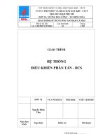
M OVERALL ELECTRICAL WIRING DIAGRAM
1 TOYOTA INNOVA
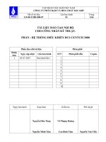
Position of Parts in Engine Compartment
A3
B1
E1
F7
F6
F5
H6
A4
B2
A7
C5
H2
C2
H1
F1
F2
C4
A6
A8
E4
H4
C1
A1
-1-
E3
H3
F4
A2
A5
C3
Position of Parts in Engine Compartment
A
A
A
A
A
A
A
A
1
2
3
4
5
6
7
8
A/C Ambient Temp. Sensor
A/C Compressor
A/T Fluid Temp. Sensor
Air Flow Meter
Airbag Sensor (Front LH)
Airbag Sensor (Front RH)
Alternator
Alternator
B
B
1 Back-Up Lamp SW
2 Brake Fluid Level Warning SW
C
C
C
C
C
1
2
3
4
5
E
E
E
1 ECT Solenoid
3 Engine Hood Courtesy SW
4 Engine Oil Pressure SW
F
F
F
F
F
F
1
2
4
5
6
7
Fog Lamp (Front LH)
Fog Lamp (Front RH)
Fuel Injector (No.1)
Fuel Injector (No.2)
Fuel Injector (No.3)
Fuel Injector (No.4)
H
H
H
H
H
1
2
3
4
6
Headlamp (LH)
Headlamp (RH)
Horn (High)
Horn (Low)
Heated Oxygen Sensor (Bank 1 Sensor 1)
Camshaft Position Sensor
Camshaft Timing Oil Control Valve
Clearance Lamp (Front LH)
Clearance Lamp (Front RH)
Crankshaft Position Sensor
-2-
Position of Parts in Engine Compartment
A1
A2
A3
A4
A5
Black
Gray
Gray
Black
Yellow
1
1
1
2
A6
1
2
A7
Yellow
2
3
4
5
1
2
A8
B1
B2
Black
Gray
Gray
1
1
2
1
2
3
4
1
1
2
2
C1
C2
C3
C4
C5
Black
Gray
Black
Black
Gray
1
1 2
2
1
2
1
1
2
2
3
E1
E3
E4
F1
F2
White
Black
Black
Brown
Brown
1
1
1
2
3
4
5
6
7
8
2
2
2
1
F4
F5
F6
F7
H1
Brown
Gray
Brown
Gray
Black
1
1
1
1
2
2
2
H2
H3
H4
H6
Black
Black
Black
Black
1
1
1
2
1
3
1
2
3
4
-3-
2
1
2
3
Position of Parts in Engine Compartment
I2
N1
I3
I4
T5
S3
T4
W1
T1
W3
T16
S2
T17
J37
S1
J1
T8
T7
P2
S5
I1
K1
N2
V3
P1
-1-
S6
S7
S4
R1
W2
Position of Parts in Engine Compartment
I
I
I
I
1
2
3
4
Ignition Coil (No.1)
Ignition Coil (No.2)
Ignition Coil (No.3)
Ignition Coil (No.4)
J 1 Junction Connector
J 37 Junction Connector
K
1 Knock Control Sensor (Bank 1)
N
N
N
1 Park/Neutral Position SW
2 Noise Filter (Ignition)
2 Noise Filter (Ignition)
P
P
1 Power Steering Oil Pressure SW
2 Pressure SW
R
1 Rear Washer Motor
S
S
S
S
S
S
S
1
2
3
4
5
6
7
Security Horn
Skid Control ECU with Actuator
Speed Sensor
Speed Sensor (Front LH)
Speed Sensor (Front RH)
Starter
Starter
T 1 Throttle Body Assembly
T 4 Transmission Revolution Sensor (Input)
T 5 Transmission Revolution Sensor (Output)
T 7 Turn Signal Lamp (Front LH)
T 8 Turn Signal Lamp (Front RH)
T 16 Turn Signal Lamp (Front Side LH)
T 17 Turn Signal Lamp (Front Side RH)
V
3 VSV (Purge)
W 1 Water Temp. Sensor
W 2 Windshield Washer Motor
W 3 Windshield Wiper Motor
-2-
Position of Parts in Engine Compartment
1
I1
I2
I3
I4
Black
Black
Black
Black
2
3
4
1
2
3
4
1
2
3
4
1
2
3
4
J1
J 37
K1
N1
White
White
Black
Gray
1 2 3
4 5
6 7 8 9 10 11 12
1 2 3
4 5
6 7 8 9 10 11 12
1
2
1
5
6
2
7
3
8
4
9
N2
N2
P1
P2
R1
Gray
Gray
Black
Gray
Black
1
1
1
2
2
1
1
2
2
(Before Sep. 2008 Production)
(From Sep. 2008 Production)
S1
S2
S3
Black
Black
Black
1
1
1
2
23
24
3
4
13
25
5
6
14 15 16
26 27 28
7
8
9
2
3
10 11 12
17 18 19
29 30 31
20 21 22
32 33 34
S4
S5
S6
Gray
White
Black
S7
T1
Black
1
1
2
1
2
1
1
2
3
4
T4
T5
T7
T8
T 16
Black
Black
Gray
Gray
Gray
1
1
2
1
2
1
2
1
-3-
2
2
5
6
Position of Parts in Engine Compartment
T 17
V3
W1
W2
W3
Gray
Black
Black
Black
Black
1
1 2
2
1
1
2
2
1
2
4
-4-
3
5
Wire and Wire , Ground Points in Engine Compartment
Engine Wire
EC
ED
EB1
Sensor Wire
EA2
Engine Room
Main Wire
EA1
EB
EA
Engine No.2 Wire
-1-
Wire and Wire , Ground Points in Engine Compartment
1 2 3
EA1
EA2
White
White
4 5
6 7 8 9 10 11 12 13
5 4
1
3 2 1
13 12 11 10 9 8 7 6
EB1
Black
2
1
1
2
-2-
2
2
1
2 TOYOTA INNOVA
P o w e r S o u rc e
1
5 AM2
IG2 6
4
3
2
W–R
∗ 1 : Before Sep. 2008 Production
∗ 2 : From Sep. 2008 Production
Ig n itio n
R
B
R
R
R
ST2
1 A (∗1)
1 B (∗2)
N 2(A), (B)
Noise Filter
(Ignition)
R
R
R
R
R
15A
INJ
5 ID1
I1
Ignition Coil
(No. 1)
1
I2
Ignition Coil
(No. 2)
1
+B
I3
Ignition Coil
(No. 3)
1
+B
I4
Ignition Coil
(No. 4)
1
+B
+B
10 2D
W–R
IGT1
IGF
GND
IGT2
IGF
GND
IGT3
IGF
GND
IGT4
IGF
GND
3
2
4
3
2
4
3
2
4
3
2
4
R
R
W–B
G–R
G
W–B
G–R
G–B
W–B
G–R
R–L
W–B
G–R
R
1
II2
W–B
W–B
G–R
30A
AM2
9 A
8 A
J12(A), J13(B)
11 B
Junction
Connector
10 B
4 1B
W–B
W–R
TOYOTA INNOVA (EM00K2EV)
6 2C
I9
Ignition SW
7 A
G–R
G–R
G–R
G
G–B
R–L
R
1 1A
W
Engine ECU
< 3–14>
W–B
Battery
Rear Side of the
Cylinder Block
EC
M
P o w e r S o u rc e
1
E n g in e C o n tro l
4
3
2
G(∗4)
O(∗3)
R–W
B–O
B–R
B–O
IG2 6
5 AM2
B
ST2
L
O(∗3)
I9
B
G(∗4)
Ignition SW
W–G
B
C
D
E
F
G
H
I
R–W
6 2C
L
14 2D
22 2S
6 2L
6 2M
11 2D
B–O
1 1H
II2
W–G
1
L
W–L
1 2G
6 1J
B
6 A
J 4(A), J 5(B)
7. 5A MET
15A INJ
7. 5A IGN
W–R
8 A
J 4(A), J 5(B)
Junction
Connector
11 B
Junction
Connector
2 B
7. 5A OBD
4 1J
1 1J
2 1J
C/OPN
Relay
1 2D
1
MAIN Relay
25A EFI
B–O
B–R
B–O
B–O
3 1B
B–O
1
1 1F
W–R
W–L
R–W
B
4 1B
8 1J
4 ID1
5
II4
LG–B
W–B
5
12 EA1
F13
Fuel Suction Pump
and Gage Assembly
M
Pump
6 BA1
B–R
B
(∗4)
4
1 IJ1
B–R
2
3 1J
W–B
B
(∗4)
B
(∗3)
J37
Junction
Connector
B–R
30A AM2
50A BATT P/I
10A ETCS
1
5 1J
1
LG–B
2
7 1J
B–R
2
100A ALT
TOYOTA INNOVA (EM00K2EV)
B
A
1 1A
B
B
W
B–O
7
5 BA1
1
Battery
11
W–B
∗ 3 : Before Sep. 2008 Production
∗ 4 : From Sep. 2008 Production
EB
LG–B
W–B
J1
Junction
Connector
J20
Junction
Connector
Left Side of the
Fender Apron
J
K
IF
Cowl Side
Panel LH
L
M OVERALL ELECTRICAL WIRING DIAGRAM
(Cont. next page)
3 TOYOTA INNOVA
3 TOYOTA INNOVA (Cont' d)
(Cont. next page)
∗ 1 : w/ Accessory Meter
∗ 3 : Before Sep. 2008 Production
∗ 4 : From Sep. 2008 Production
E n g in e C o n tro l
A
B
C
G(∗4)
5
8
7
6
G(∗4)
O(∗3)
O(∗3)
BR
B–O
IGSW
9 A
FC
25 A
# 40
30 B
W
7 A
+BM
B
Y
LG–B
B–O
J14(A), J15(B)
Junction
Connector
V3
VSV (Purge)
B
B
9 A
L–Y
W
(Shielded)
E
B
3
1
OX1A
LG–B
+B
2
HT1A
E2
4
H6
B–O
BR
B
Heated Oxygen Sensor
(Bank 1 Sensor 1)
L
1 C
1 D
9 B
2
K
# 30
HA1A
A1A+
21 D
1
J
2 C
# 20
R–W
PRG
23 C
L
8 B
5 C
# 10
R–B
11 A
C10(A)
R–B
W
R
L
6 C
ST1–
BATT
Check Engine
1 IE1
E 9(A), E10(B), E11(C), E12(D)
Engine ECU
J12(A), J13(B)
Junction Connector
7 B
16 A
3 A
B
10 A
+B
F7
Fuel Injector
(No. 4)
F6
Fuel Injector
(No. 3)
2
Combination Meter
B–R
B–R
2
G
3 B
J12(A), J13(B)
Junction
Connector
R–L
1 A
MREL
21 A
1
F5
2
3 A
L
B
W–G
8 A
D
39 A
4 A
4
C
L
II4
2
L
(∗1)
S13
Stop Lamp SW
1
2
Fuel Injector
(No. 2)
13 ID2
1
F4
R–L
B–O
II4
3
Fuel Injector
(No. 1)
II4
B
W–G
1
14
4
1
L
(∗1)
Stop Light
System
< 6–3>
B
W–G
B–R
B–R
1
B
TOYOTA INNOVA (EM00K2EV)
I
B–R
Combination
Meter< 20–5>
L
G
H
B–R
B–R
B–R
F
B–O
B–O
E
B
R–W
B
D
A
M
(Cont. next page)
∗ 3 : Before Sep. 2008 Production
∗ 4 : From Sep. 2008 Production
E n g in e C o n tro l
A
B
C
D
9
G(∗4)
12
11
10
G(∗4)
O(∗3)
O(∗3)
A
B
BR
B
BR
BR
VTA
VC
4
6
5
SPD
ELS
12 A
STA
G–W
B–Y(A/T)
L–Y(M/T)
8 B
15 A
F/PS
ALT
V–R
32 B
10 D
NSW
G
30 A
VC
VTA1
B
(w/ SRS)
18 D
20 D
VTA2
G
19 D
M–
L–Y
(A/T)
B–R
LG
(Shielded)
4 D
M+
Stop Lamp SW
< 6–4>
VTA2
5 D
GE01
E2
THW
M–
1
W
8 D
28 D
32 D
THA
M+
2
B
29 C
BR
BR
E2G
B
30 C
L–B
VG
L–R
L–W
28 C
2
Combination Meter
< 20–3>
4
Combination SW
< 8–5>
THA
2
ST Fuse
< 1–2>
E2G
W1
Water Temp. Sensor
VG
3
A4
E2
Air Flow Meter
+B
Alternator
< 1–4>
E2
5
LG–B
TOYOTA INNOVA (EM00K2EV)
1
Airbag Sensor
Assembly Center
< 11–4>
3
1
Park/Neutral Position SW
(A/T)< 1–3>
ST Fuse (M/T)
< 1–2>
BR
BR
BR
BR
B
T1
Throttle Body Assembly
4 B
STP
E 9(A), E10(B), E11(C), E12(D)
Engine ECU
KNK1
29 D
NE–
G2
EKNK
30 D
26 D
NE+
34 D
ME01
E1
27 D
3 D
3 C
VCP2
27 A
EPA2
21 A
VPA2
19 A
VCPA
26 A
EPA
20 A
VPA
18 A
OC1–
12 D
OC1+
13 D
G
P–L
Y
W–L
BR–W
C2
Camshaft Timing Oil
Control Valve
J7
Junction Connector
2
V
W–B
1
6
VPA
A17
V
2
5
EPA
Accelerator Position Sensor
BR
3
4
VCPA
BR
10
3
VPA2
1
W–B
1
LG–R
E
3
GR–G
NE
2
EPA2
C5
1
NE–
1
VCP2
(Shielded)
2
Crankshaft
Position Sensor
W–B
C1
Camshaft
Position Sensor
K1
Knock Control
Sensor (Bank 1)
2
L
Y
(Shielded)
G
R
W
B
1
2
BR–Y
1 A
(Shielded)
BR–R
2 A
E
W–B
J12(A), J13(B)
Junction Connector
BR
W
1 EB1
(Shielded)
B
2 EB1
6 B
8
9
7
ED
Rear Side of the
Cylinder Block
C
M OVERALL ELECTRICAL WIRING DIAGRAM
3 TOYOTA INNOVA (Cont' d)
3 TOYOTA INNOVA (Cont' d)
∗ 2 : w/ Rear Window Defogger
∗ 3 : Before Sep. 2008 Production
∗ 4 : From Sep. 2008 Production
E n g in e C o n tro l
A
B
13
G(∗4)
16
15
14
O(∗3)
BAT
TAC
WFSE
9
15
17 D
16 D
IGT3
15 D
IGT4
14 D
7 2B
4 2B
1 B
4 B
J28(B)
Junction
Connector
23 D
W–B
Airbag Sensor Assembly Center
< 11–2>
Combination Meter
< 11–2>
Airbag Sensor
Assembly Center
< 11–3>
Skid Control ECU
with Actuator
< 10–3>
J26(B)
Junction
Connector
12 B
Ignition Coils
< 2–3> < 2–4>
5 2J
IGF1
G–R
P1
Power Steering Oil
Pressure SW
8 B
2 A
G
G–B
R–L
R
W–B
W–B
W–B
W–B
R
G–Y
1
1 A
G
6 D
SIL
B–Y
(w/ SRS)
7 D
IGT2
6 2J
18 ID2
13 B
P–B
(w/ SRS)
4 C
IGT1
21 2Q
W
(w/ SRS)
7 C
E02
22 2Q
P–L
(w/ ABS)
22 A
E01
TC
5 2Q
L–Y
(w/ ABS)
32 C
E03
17 B
6 2Q
V
WFSE
W
(w/ ABS)
E04
EC
BR
35 B
TACH
E 9(A), E10(B), E11(C), E12(D)
Engine ECU
PSW
B–Y
(w/ SRS)
1 B
THWO
CG
4
R–Y
14 B
ACT
P–B
25 B
W
AC1
SG
5
6 2O
B–W
P
24 B
ELS3
A/B
11
P–B
R–Y
R–L
Y
B
(∗2)
3 B
13
P–B
6 2N
TC
SIL
7
R–Y
16 2Q
TS
12
W
B–W
B–W
P
22 2O
G(∗4)
O(∗3)
Combination Meter
< 20–5>
Combination Meter
< 20–5>
A/C Amplifier
< 21–6>
DEF Relay
< 17–2>
TOYOTA INNOVA (EM00K2EV)
32 2Q
D3
DLC3
16
6 B
J14(A), J15(B)
Junction
Connector
W–B
C
V
W–B
Instrument Panel
Reinforcement
Center
IG
EC
Rear Side of
the Cylinder Block
IH
Instrument Panel
Reinforcement LH
M
Position of Parts in Body
M2
B12
O3
D12
D5
D9
* 1:Before Sep. 2008 Production
* 2:From Sep. 2008 Production
O2
C15
D8
D11
D4
D7
B10
B11
(*1)
(*2)
F11
D10
D6
F13
-1-
F14
J36
J35
B9
L2
C16
C17
Position of Parts in Body
B 9 Back Door Lock Assembly
B 10 Blower Motor (Rear)
B 11 Blower Resistor (Rear)
B 12 Blower SW (Rear)
C 15 Center Stop Lamp
C 16 Clearance Warning ECU
C 17 Clearance Warning ECU
D 4 Door Courtesy SW (Driver's Side)
D 5 Door Courtesy SW (Front Passenger's Side)
D 6 Door Courtesy SW (Rear LH)
D 7 Door Courtesy SW (Rear RH)
D 8 Door Lock Assembly (Driver's Side)
D 9 Door Lock Assembly (Front Passenger's Side)
D 10 Door Lock Assembly (Rear LH)
D 11 Door Lock Assembly (Rear RH)
D 12 Door Lock Control Receiver
F 11 Front Seat Inner Belt (Driver's Side)
F 13 Fuel Suction Pump and Gage Assembly
F 14 Front Seat Inner Belt Assembly (Front Passenger's Side)
J 35 Junction Connector
J 36 Junction Connector
L
2 License Plate Lamp
M
2 Map Lamp
O
O
2 Outer Rear View Mirror (LH)
3 Outer Rear View Mirror (RH)
-2-
Position of Parts in Body
B9
B 10
B 11
B 12
C 15
White
Black
Black
White
Gray
1
1
1 2
2
3 4
1
2
3
4
2
3
4
5
1
2
6
C 16
C 17
D4
D5
White
White
White
White
1
1
1
2
3
7
8
9 10 11 12
4
5
1
6
2
3
4
5
6
7
8
9
10 11 12 13 14 15 16 17 18 19 20 21 22 23 24
D6
D7
D8
D9
D 10
White
White
White
White
White
1
1
1
2
5
6
7
3
8
4
1
9 10
5
2
6
5
4
1
9 10
5
7
F 11
F 13
F 14
White
Black
White
3
8
4
1
2
3
4
1
5
2
4
9 10
4
9 10
1 2
3
5
J 35
J 36
L2
M2
O2
White
White
White
White
White
3
8
3
8
D 12
7
2
7
White
1
1
2
6
D 11
2
6
3
8
White
1 2
1
7
4
5
6
9 10 11 12
1
7
2
8
3
4
5
6
2 1
9 10 11 12
O3
White
2
1
4
3
6
5
-3-
2
2
1
4
3
6
5
Position of Parts in Body
R12
T15
P7
S15
P10
R13
* 1:Before Sep. 2008 Production
* 2:From Sep. 2008 Production
T14
P12
P5
P9
P6
S17
S14
R8
P11
R10
P8
R7
S16
R11
(*1)
(*2)
R6
S18
-1-
S19
R9
U2
U4
(*1)
(*2)
U3
U5
Position of Parts in Body
P 5 Power Window Master SW
P 6 Power Window Regulator Motor (Front LH)
P 7 Power Window Regulator Motor (Front RH)
P 8 Power Window Regulator Motor (Rear LH)
P 9 Power Window Regulator Motor (Rear RH)
P 10 Power Window SW (Front Passenger's Side)
P 11 Power Window SW (Rear LH)
P 12 Power Window SW (Rear RH)
R
R
R
R
R
R
R
R
6
7
8
9
10
11
12
13
Rear Combination Lamp (LH)
Rear Combination Lamp (RH)
Rear Cooler Relay
Rear Window Defogger
Rear Window Defogger
Rear Wiper Motor
Room Lamp (Center)
Room Lamp (Luggage)
S
S
S
S
S
S
14
15
16
17
18
19
Speaker (Front Door LH)
Speaker (Front Door RH)
Speaker (Rear Door LH)
Speaker (Rear Door RH)
Speed Sensor (Rear LH)
Speed Sensor (Rear RH)
T 14 Tweeter (LH)
T 15 Tweeter (RH)
U
U
U
U
2
3
4
5
Ultrasonic Sensor No.1 (LH)
Ultrasonic Sensor No.1 (RH)
Ultrasonic Sensor No.1 (LH)
Ultrasonic Sensor No.1 (RH)
-2-
Position of Parts in Body
P5
P6
P7
P8
White
Black
Black
Black
1
1
3
2
4
5
6
7
8
3
9
4
5
2
1
6
3
1
2
4
5
2
6
10 11 12 13 14 15 16 17 18
P9
P 10
P 11
P 12
R6
Black
Black
Black
Black
White
1 2 3 4 5
1 2 3 4 5
1 2 3 4 5
1
2
1
2
3
4
5
6
R7
R8
R9
R 10
R 11
R 12
R 13
White
White
White
White
White
White
White
1
1
1
1
2
2
1
1
2
3
4
5
2
3 4 5
1
2
6
S 14
S 15
S 16
S 17
S 18
S 19
White
White
White
White
Gray
White
1
1
1
1
2
2
2
2
1
2
1
1
2
T 14
T 15
U2
U3
White
White
Black
Black
3
4
1
2
3
1
4
U4
U5
Black
Black
1 2 3 4 5 6
1 2 3 4 5 6
-3-
2
1
2
2
F
[Body]
Door Lock Control Receiver
Rear Cooler
Relay
Clearance
Warning
ECU
TOYOTA INNOVA (EM00K2EV)
Wire and Wire , Ground Points in Body
* 1:Before Sep. 2008 Production
* 2:From Sep. 2008 Production
Roof Wire
Front Door
RH Wire
BC1
Rear Door
No.1 Wire
RH
Instrument
Panel Wire
BK
BB1
Back Door
No.1 Wire
Front Door
LH Wire
(*1)
(*2)
BA1
BE1
BE2
Luggage
Room
No.2 Wire
Rear Door No.1
Floor Wire
Wire LH
Frame Wire
BD2
-1-
BD1
BJ
Wire and Wire , Ground Points in Body
1
2
3
4
5
6
7
8
1
2
3
4
6
7
8
9 10
1
2
3
4
BA1
BB1
White
White
4
3
2
1
8
7
6
5
1
2
3
4
6
7
8
9 10
5
4
3
2
1
10 9
5
8
7
6
BC1
BD1
BD2
White
White
White
5
5
4
3
2
1
10 9
8
7
6
2 1
4 3
1 2
3 4
BE1
BE2
White
White
4
3
2
1
1 2 3
3
2
1
4 5 6
6
5
4
-2-
1
2
3
3
2
1
4
5
6
6
5
4
Camry
Jan.
ACV30, 31, MCV30
1300 (13.3, 189)
245–539
(2.5 – 5.5, 36 – 78)
A
B
C
Printed in Japan I
’04