DSpace at VNU: Image and video compression for wireless networks
Bạn đang xem bản rút gọn của tài liệu. Xem và tải ngay bản đầy đủ của tài liệu tại đây (5.91 MB, 14 trang )
VNU. JOURNAL OF SCIENCE, Mathematics - Physics, T.XXII, N01, 2006
IMAGE AND VIDEO COMPRESSION FOR WIRELESS NETWORKS
Ho Anh Tuy
Hanoi University o f Technology
N guyen Vinh An
Hanoi Open University
Abstract. The demands for transmission of image, video and multimedia over
wireless networks are increasing very rapidly. The inherently characteristics of
wireless medium as bandwidth narrowing, interferences and fading are big
challenges. The traditional compression techniques can not adapt to this
changes. In this paper, we will discuss of issues of using wavelet compression
for image and video over wireless networks. This paper also introduces some
change of wavelet parameters in order to improve quality of transmission image
and video over wireless network conditions.
1. I n tr o d u c tio n
The
tra d i ti o n a l
mobile
networks
are
used
for
low
-
rate
audio
communications. New generation of mobile comm unications is em e rgin g to t r a n s f e r
d a ta trafic a t m uch higher bit rate. The dem an ds for m ultimedia, im age a n d video
over wireless netw ork s are rapidly increasing. F u t u r e I n t e r n e t will allow u se rs
access from mobile appliances (PDAs, s m a r t phone, Web pads, h a n d PCs...) and
high b a n d w id th applications (m-commerces, m ultim edia E-mail, video telephone,
wireless LANs, PANs).
T r a n s m i s s io n of Image a nd Video over Wireless Networks a re challe nging
because of th e highly variable n a t u r e of the wireless link. Radio is a n i n h e r e n tly
unreliable t r a n s m i s s io n medium when compared to a wired link due to inteference
and fading c re a t e h igher bit errors. Typical wireless c hannels are noisy a n d of
n arrow b a n d w id th . For example, a customer using a code-division multiple-access
(CDMA) has only a 9.6 kbps bandw idth. Even if the b a n d w id th i n cre as es up to 2
Mbps for t h e 3G wireless, it is still not comparable to th e b a n d w id th of bro ad ba n d
optical comm unication syste ms (ATM could allocate dozens of Mbps to end users).
Time-varying c h ar acteristics of wireless channel a n d limited b a tt e r y resource in
h an dh eld devices is a n o th e r issue for scalable video st r e a m in g over wireless link
with Quality of Service (QoS). Meanwhile, the capacity of a wireless c h a n n e l is
fluctuated d ue to th e changing distance between the t r a n s m i t t e r a nd t h e receiver.
So it is i m p o r t a n t to e stim a te the available wireless network condition dyna mically
and it is n e ce ssa ry to apply appro priate d video compression stra te g y to h a n d le the
variability of wireless networks.
33
Ho Anh Tuy, Nguyen Vinh An
34
2. Im age c o m p r e ss io n t e c h n iq u e s
There are four common methods for compression, Discreate Cosine T r a n sf o r m
(DCT), Vector qu a n ti za tio n (VQ), Fra ctal Compression and Discrete Wavelet
Transform (DWT).
DCT is a lossy compression algorithm t h a t samples an image a t r e g u la r
intervals, analyzes the frequency components p r e s e n t in the sample, discards those
frequencies which do not affect the image as the h u m a n eye perceives it.
Vector qu an tizatio n (VQ) is a lossy compression t h a t looks a t a n a r r a y of data,
not an individual value. It compresses r e d u n d a n t d a ta while a t the sam e time
r etaining th e desired object or da ta s t r e a m ’s original intent.
Fractal compression is a form of VQ and is also a lossy compression. The self
similar sections of image is located and then using fractal algorithm to handle them.
DWT analyzes signals into wavelets-functions t h a t have both time and
frequency domains. The process is perform on the entire image, which differs from
DCT t h a t works on sm aller block (8 x 8 picxels).
2.1 D iscrete Cosine T r a n s fo r m (DCT)
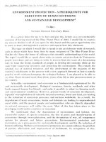
Currently, DCT is quite popular in m any compression products such as J P E G .
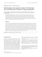
Image compression using DCT is illustrate d in figure 1 .
F ig u r e 1. JP E G compression.
The general forward a nd inverse DCT transfo rm for a 2D (N by M image) is
defined by the following equation
DCT:
s
EY \ _ 2 r v w
\ v l ' v l /Y
\
( 2x + X)vn
{2y+\)nn
F(w,v) = f - C ( t < ) C ( v ) X
f ( y , x ) c o s -----—^----- COS----- — ----N
y=0
x=0
2
N
+
\)U 7 T
(1)
2N
IDCT:
t<:
i\ _
2
V
' V
/ơ .ỹ ) = f r Z
ỵ
N „ = 0 1'=0
n t
\ n t
\E V
\
( 2x
(2y + \ ) v n
C(u)C(v)F(u,v)c o s ------ — ---------COS------- —
2N
; ------
/o x
(2)
2N
The main d isa dv an tag e s of DCT is t h a t when the coded bit r a t e is lower t h a n
a certain value (0.25 bits/pixel), th ere are blocking effects in the decoded image, due
to t h e 8 x 8 block two d i m e n s i o n a l DCT. In a n o t h e r issue, for t h e w ir e le s s n e tw o r k s ,
the channe ls are noisy, th e blocks are lost because Huffman coding is a variable
length code. The noisier th e channe l is, the more blocks are lost.
I m age a n d Video C o m p re ssio n fo r Wireless N e t w o r k s
35
2.2 D iscrete W avelet T ra n sfo rm (DWT).
2.2.1
The wavelet decomposition h as been proved to be a good tool for image
compression recently. It performs b etter t h a n DCT in term of compression ratio and
quality of p icture which is reproduced. The new J P E G 2000 s t a n d a r d s adopt
w av elet s u b b a n d coding, w h e r e t h e enc od er tiles t h e i m a g e in to blocks of N X N
pixels (N being a power of 2), calculates a 2-D Discrete Wavelet Transform (DWT),
q u a n t i z e s t h e t r a n s f o r m coefficients a n d encodes t h e m u s in g a r i t h m e t i c coding. Th e
discrete-time wavelets have general form:
1
a
-
1/2
¥
t-b
(3)
a
The v a ri a b le a is used to scale the wavelet V
ụ(t) by powers of two and variable
b is used to t r a n s l a t e the wavelet in integer amounts. To analyse d a ta a t different
resolution, a function W(t) is used in conjunction with the m oth e r wavelet. Here
W (0 = ! ( - ! ) * C y F (2 / + *)
(4)
Ck are the w a v ele t coefficients which satisfy (5)
N- \
N-\
N-1
I C , = 2 and ỵ c kc „ = ĩ ổ h0
k=0
*=0
(5)
In th is case 5 is the delta function and b is the location index.
In forward DWT, image is seperated into low-pass samples, representin g a
low-resolution version of the original image and high-pass samples, rep resen tin g a
details which a re needed for the perfect reconstruction of the original image.
V e rtic a l
W a v e le t
Hl|fc QgriMotRl
Pngmnrtw
AU'Vtotkvl
P m tn u k t
A H Piapm òct
Tm pm àm
M l
V e rtic al
B H iH criM dil
FmqMKlei
S c a lin g
F u n c tio n
U w V W e*
Frwpwnci*
V b tú a l
Law H odm tal
Fraqittttfcf
Wsvxlet
ị
H c rim n ta l
Fuqunp*
I
S c a lin g
F n n c tijjn
Froqvoekfl
HH
EBsfaVwk«]
HL
LH
ỸTỆQmcbỆ
Vertical
Scaling
Function
ĩm Hnrímrial
ftgncia
L m W iai
Ynqaaàm
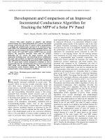
F ig u r e 2. The level 1 of wavelet decomposition process
J J
^
Ho Anh Tuy , Nguyen Vinh An
36
The entire process is carried o u t by excuting a 1 -D subband decomposition
twice, first in horizontal t h e n in the veritcal (orthogonal). For example, the low pass
subband (Ll) resulting from the horizontal is f u r t h e r decomposed in th e veritcal,
leading to L L 1 a nd L H 1 subband. Similarly, the high pass sub b a n d H I is f u r t h e r
decomposed into HL1 a n d H H l . An example of the proccess of one level wavelet
decomposition is depicted in figure 3 a n d the d e m o nstr a tio n of picture is shown in
figure 4..
F ig u r e 3. The proccess of one level wavelet decomposition.
The second level of decomposition can be repeated for existing LL1 subband.
This iterative process results in multiple ”transfo rm levels”. If an image is
decomposition into K levels th en the total n u m b e r of sub b a n d s is 3 K + 1. The
process of decomposition of an image in three level as shown in figure 3. N u m be r of
required subbands afte r th r e e level decomposion of 2D image is depicted in figure 5.
LL
HL
LH
HH
HL
HL
LH
HH
LH
HH
Figure 4. Three level of 2-D Discrete Wavelet Decomposition
Im a g e a n d Video C o m p r e s s i o n f o r Wireless N e t w o r k s
37
2.2.3 Q u an tiz atio n is the process by which th e coefficients a re reduced in
presision. The qu a n ti za tio n can be lossy or lossless.
Each subband of the wavelet decomposition is divided into r ec tan g u lar blocks
(Code blocks), which are coded indep enden tly u sin g a rith m e tic coding. These code
blocks are coded a t a bit-plane at a time, s t a r t i n g with the most significant bitplane with a non-zero element to the least significant bit-plane.
2.2.4 Wavelet h a s some main a d v an tage s over DCT, includes:
• Improved scalability: This is because th e wavelet t ran s fo rm process can be
repe ate d for as m an y time as needed. The decoder can stop any time if
needed, as full resolution of th e image m a y not required.
•
Higher efficiency a t low bit rates.
•
It provide h igher compression ratio a n d b e tt e r quality of reproduced image.
• The disadvance of it is using wavelet require more calculations when
comparing with DCT. This leads to more complexing in th e h a r d w a r e and
software implementations.
2.3. The J P E G (J o in t P h o to g ra p h ic E x p e r ts Group)
J P E G is well-known image compression method based on DCT algorithm.
J P E G compression can be done a t different u s e r defined compression levels, which
de te rm ine how much an image is to be compressed. The compression level is
directly related to the image quality. Besides th e compression level, th e image scene
itself also has an im pact on th e resulting compression ratio. The sa m e compression
level applied on simple scene may produce a sm a lle r file (higher compression ratio)
t h a n on a very complex a nd p a tt e r n e d scene (lower compression ratio).
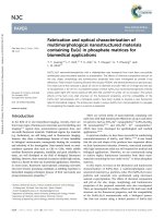
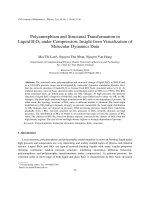
2.4. J P E G 2000 sta n d a r d s .
The J P E G s t a n d a r d s using DCT and J P E G 2000 using DWT. The difference in
quality of image when compressed using J P E G a n d J P E G 2000 can be seen in the
íìgureõ.
J P E G 2000 s t a n d a r d provides a set of f e a t u r e s t h a t are of vital importance to
m an y emerging applications. Some of the fe a t u r e s t h a t th is s t a n d a r d possesses are:
Superior low bit-rate p erform ance: This offers b e t t e r performance t h a n c u rr e nt
s t a n d a r d s a t the low bit-rate.
•
Lossless a nd lossy compression.
• Progressive transm ission by pixel accuracy a n d resolution: Progressive
t r a n s m iss io n allows pictures to be reconstructed with increasing pixel
accuracy or sp atia l resolution. This needs for m an y applications and for
different t a r g e t devices.
• Region o f Interest Coding: This f e a t u r e allows u se r defined Regions-OfI n t e r e s t (p arts of a image t h a t are more i m p o r t a n t t h a n other pa rts of it) in
the image to be compressed with b e tt e r quality t h a n th e r e s t of the image.
Ho Anh Tuy , Nguyen Vinh An
38
• R obustness'to bit-errors: It is desirable to consider ro bustness to bit-errors
while designing the codestream. This feature is very im p o r ta n t for wireless
communication applications.
Original Image
40:1 compressed J P E G
40:1 Compressed J P E G 2000
F ig u r e 5. Compare the quality of image using J P E G a n d J P E G 2000.
3. V i d e o c o m p r e s s i o n T e c h n o l o g y
3.1.
Video compression is performed when an i n p u t video stre am is -analyzed
and r e d u n d a n t information is discarded. Each event is t h e n assigned a codecommonly occurring events are assigned few bits and r a r e events will have more
bits. This is called variable length encoding respectively (VLC). One of the bestknown video st r e a m in g techniques is the s t a n d a r d called MPEG {Motion Picture
Experts Group). The basic principle of MPEG is to compare two compressed images
to be tr a n s m i t te d over the network and using the first compressed image as a
Im a g e a n d Video C o m p re ssio n f o r Wireless N e t w o r k s
39
reference frame (called an I-frame), only sending the p a rt s of the following images
(B-frame a nd P-frame) t h a t differ from the reference image.
3.2. There are five MPEG s t a n d a r d s being used. Each s t a n d a r d was designed
for a specific application and bit rate M P E G -1 was designed for up to 1.5 Mbps,
standad ized for compression of moving pictures a n d audio. MPEG-2 was designed
for between 1.5 and 15 Mbps. It is based on M P E G - 1 , b u t for the compression and
tra nsmiss io n of digital broadcas t television. The most significant e n h a n c e m e n t from
M P E G -1 is its ability to efficiently compress interlaced video.
The Motion Picture Exp erts Group (MPEG4) s t a n d a r d s for m ultimedia and
Web compression. MPEG-4 is based on object-based compression. Individual objects
within a scene are tracked se peratly and compresses together to create an M P E G -4
file t h a t is very scalable, from low bit rates to very high.
MPEG-4 is a new generation of In tern et- b ased video applications a nd Video
Coding Experts Group H.264 s t a n d a r d s for video compression is now widely used in
videoconferencing systems. MPEG 4 and H 263 promises to significant outperform,
providing b e tte r compression of video together with a ran ge of fea tu res supporting
high-quality, low b it-ra te str e a m in g video.
3.3. The H.261 a nd H.263 stan d ards. H.261 is an ITU s t a n d a r d designed for
two way communication over ISDN lines (Videoconferencing) a n d supports data
rates of multiples of 64Kbps. The algorithm is based on DCT a n d can be used in
intra-fram e a nd inte r- fra m e mode. H.261 supports CIF a n d QCIF resolutions.
H.263 is based on H.261 with en hanc em ents t h a t improve video quality over
modems. It support s CIF, QCIF, SQCIF, 4CIF a nd 16 CIF resolutions.
The H 264 s t a n d a r d does not explicitly define a CODEC, r a t h e r th e sta n d a r d
defines the syntax of an encoded video b its tr e a m together with th e method of
decoding this b its tr e am . The basic functional ele ments (prediction, transform,
quantization, entropy encoding) are little different from M P E G l , MPEG2, MPEG-4,
H.261, H.263.
3.4. The M P E G l , M P E G 2 , MPEG4, H.261, H.263 use 8 x 8 DCT transform.
The “Ba se line” profile H.264 uses three tran sfo rm depending on the type of residual
da ta t h a t is to be coded: a transfo rm for 4 X 4 a r r a y of l u m a DC coefficients in in tra
macroblocks, a tran sfo rm for 2 x 2 a r r a y of chro m a DC coefficients in any
mocroblock a nd a tran sform for all other 4 x 4 blocks in th e res idual data. H.264
uses scalar quantizer.
4. V id e o o v e r W ireless N e tw o r k
4.1,
three factors:
Su p po rtin g video over Wireless Networks is a h a r d problem because of
•
Scarcity of band width.
•
Time-varying error characteristics of th e t r a n s m iss io n channel.
•
Power lim ita tio ns of the wireless devices.
Ho Anh Tuy , Nguyen Vinh An
40
The emerging of 3G wireless netw orks such as GPRS (General P a c k e t Radio
Service), CDMA (Code Division Multiple Access), CDMA2000, W-CDMA boosts
enorm ous development of wireless video and services.. They are designed w ith the
capability of providing high speed d a t a services, ranging, from more t h a n 100Kbps
to several Mbps. However, transm issio n of video a nd m ulitm edia s t r e a m s over
wireless netw orks still faces several challenges. Firstly, t r a n s m iss io n of video over
wireless chann el is highly prone to errors due to m u lti-path effects, sh a do w in g and
interference. Secondly, the b a n d w id th of wireless channel can v a ry significnatly
over time. The rea son is the a m o u n t of ba nd w idth t h a t is assigned to a u s e r can be
a function of th e signal s t r e n g th (low signal stre n g th , more processing gain a t the
receiver a nd different b a n d w id th may be dynamically assigne d to th e user) and
interference level (high interference condition, heav ier channel coding). Thirdly,
m u lti-user sh a ring th e wireless channel with he terogeno us d a ta types can also lead
to significant b a n d w id th v ariation which can f u r t h e r lead to overflow of network
buffer and hence packet loss. Finally, d a ta tra n s m iss io n can be i n t e r r u p t e d
completely depending on wireless im p lem en ta tio n (handoff process, cell reselection)
4.2. Quality of Service (QoS) control in wireless netw ork s can help alleviate
th e b a n d w id th variation a nd packet delay/loss problem b u t it is often costly. For
example, to m a i n t a i n a reasona ble d a ta ra te for a use r n e a r the cell bo undary , a
large proportion of power of base station (BS) needs to be assigned which limiting
the capacity of the BS to serve other users. Video s t a n d a r d s MPEG-4 h a s a set of
tools providing improved compression efficiency and e rror r e s i li e n c e . In addition,
MPEG-4 provides scalability for both sp atia l a nd tem p o ral resolution
e nh an c em en ts. E rro r control a nd power control are two very effective approaches
for supporting quality of service. E rro r control is performed from indiv idual user
point of view by introducing red un d a n cy to combat the t r a n s m iss io n errors. One of
th e popular error coding techniques is Reed-Solomon coding, which can deal with
b u r s t error. If the original message length is M, we will add pa rity data , so the
codeword is of length N > M which can recover e rrors of length up to (N-M)/2.By
a d d in g extra p a rity d a ta of length R bytes, a t least p a r t of errors can be recovered
by th e receiver. The larg e r the value of R, more th e errors will be corrected.
Choosing of R should be considered carefully because parity d a ta in tr o d uces more
trafic to th e limited netw ork band w id th a nd may cause packet loss due to
congestion.
4 .3 . The Peak Signal-to-Noise Ratio (PSNR) m e a s u r e s th e size of error
relative to peak value of the signal Xpeak. In other word, it is used to m e a s u r e the
fidelity of a compressed image with its original. High PSNR m e a n s t h a t the
compressed image is very sim ila r to the original. The for m ular to calculate PS NR is
(6 )
2
where X peak is the peak value of the signal and Ơ2 * d is the Mean Square Error MSE
I m a g e a n d Video C o m p re ssio n f o r Wireless N e t w o r k s
41
Mean s q u a r e error (MSE) m easu re s the difference betw een the original a nd
reconstructed im age is calculated by
(7)
Here, X n, Y n N are the in p ut da ta sequence, the reconstructed d a ta a n d the
length of d a t a sequence
The W avele t transform with the advantage of multires olution is good solution
for improving PSNR. We will compare PSNRs for different resolutions with sa m e
compression ratio in table 1 .
T a b le 1. C om parison of P S N R ’s Lena colored image of size 512 X 512 for different
resolutions
No. of
Compression
Original (bits) resolutions
Ratio
0.01
(K)
After
compression
(bits)
1
62669
14.835608
2
62505
21.426299 22.403615
3
62505
28.116940 28.457747
4
62669
30.337381
5
62751
30.498237 30.167494
6
62669
30.424699 30.163027
PSNR (dB)
RED
GREEN
17.382185
6291456
29.919802
BLUE
19.314852
20.806499
27.138719
28.922634
I
29.289699
29.162789
4.4.
Pow er control is performed by controlling th e t r a n s m iss io n power a n d
tra n s m iss io n r a t e for a group of users. So e rror control a nd power control
technique s a r e n ecessary to ensu re high-quality video delivery from application
level a n d t r a n s m i s s i o n level.
It. is n e c e ssa r y to u n d e r s t a n d overall wireless system performance (such as
capacity) w h e n multiple types of traffic, each with distinct chara cteristic a re
p r e s e n t in th e s a m e sector.
5. N e w tr e n d s in im a g e and v id eo c o m p r e ss io n
5 .1 .
C u r r e n t l y , video communications are carried out using source coders a nd
c h an n e l coders designed ind ep e nd en t of each o th er based on the theoretic al
foundation of S h a n n o n ’s “separation principle” , which s t a te s t h a t this se p a r a t io n is
optimal [4].
However, w h e n considering wireless video communications, th e r e are some
rea so n s not to a d h e r e to the separation principle. For example, S h a n n o n ’s work
42
Ho Anh Tuy , Nguyen Vinh An
make no a s s u m p t i o n ab o ut the error characteristics of the ch an n e l on which data
would tr av e r se. It also doesn’t tak e into account th e optimization possible in
c han n e l utiliza tion thro ug h statical multiplexing. This is true for all po pu lar video
s t a n d a r d s , including MPEG-1, MPEG-2, H.261 and H.263. Coders are designed
with little r e g a r d to the error characteristics of the channel.
5.2. Although existing compression techniques h e l p fit video s t r e a m s into the
b a n d w id th available in wireless channels, th e r e are a n u m b e r of issues which affect
th e memory, c o m pu tation al capabilities and in te r n a l da ta t r a n s f e r c h an ne ls of
wireless devices. In addition, the wireless communication e n v ir o n m e n t is highly
prone to in tro d u c e e rrors into digital bit stream s. The video compression algor ithms
remove much of th e red u n d a n cy in video data , a nd as a result, t h e effects of channel
inte rfe rence ripples through not j u s t the c u r r e n t image being display, b u t also
successive im ages.T h e predictive techniques used in MPEG c au se errors in a
r ec o nstructe d video frame to pro pagate th ro ug h time into fu tu re frames. This can
also cause to lose synchronization in decoding process.
5.3. T h e selection of an image compression
algorithm for video and
m u ltim e d ia comm unication depends not only on the trad ition a l criterial of
achievable compression ratio a nd the quality of reconstructed images, it also
depends on associated energy consumption and ro bustness to h i g h e r bit e rro r rates
Wavelet a lg o rith m enables significant reduction in com putation as well as
co m m unication needed, with m inim al degradation in image quality. Study has
shown t h a t the wavelet step consumes more t h a n 60% of th e CPU tim e during
image compression process. By using optimizing algorithm of th e transfo rm step,
pe rform ance a n d energy r e q u ir e m e n ts of the en tire image compression process can
be significantly improved.
5.4. We know t h a t forward wavelet transfo rm uses a 1 -D subband
decomposition process where a 1 -D set of samples is converted into th e low-pass
s u b b a n d (Li) a n d high -pass subband (Hi). Dong-Gi Lee a n d Sujit Dey have
p r e s e n te d a wavelet- based transfo rm algorithm t h a t aim s a t minimizing
c om p u tatio n energy (by reducing the nu m b e r of ari th m e tic opera tio ns a nd memory
accesses) a n d communication energy (byreducing n u m b e r of t r a n s m i t t e d bits) in
“Adaptive a nd Energy Efficient Wavelet Image Compression For Mobile Multimedia
Data Services” [7]. T heir idea is exploits the num erical dist rib ution of the high-pass
coefficients to e lim in a te a large n u m b e r of sa m ples in the compression process. The
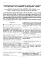
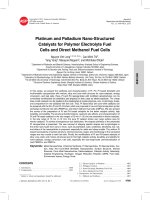
work shows t h a t on the [512x512] Lena image sample, the distrib ution of high-pass
coefficients afte r applying a 2 level wavelet as following (see figure 6 ).
We observe t h a t about 80% of the high-pass coefficients for level 1 are less
th a n 5. In th e q u a n ti z a t io n step, all small valued coefficients a re set to be zeros, so
a lots of high -pass coefficients do not have to be computed. This has two
a dv an tag e s: firstly, th e algorithm helps to reduce the computation energy consumed
d u r i n g image compression process and secondly, because the encoder and decoder
are a w a r e of th e e stim atio n technique, only small a m o u n ts of info rmation need to
Im age a n d Video C o m p r e s s i o n f o r Wireless N e t w o r k s
43
be t r a n s m i t t e d across the wireless channel, thereby reducing the comm unication
energy required.
Numerical Distribution of high-pass
coefficients
H ig h p a s s C o e ffic ie n ts (level 1) —
H igh pass C o e ffic ie n ts (le ve l 2)
Integer Value Range after transformation
F ig u r e 6. N u m e ric al distribution of high-pass coeeficients after wavelet tran sform
a t level 2 .
5.5.
Besides th e elimination techniques we have introduced, we can vary some
other wavelet p a r a m e t e r s , which can be used to minimize co m p u tatio n a nd
comm unication e n erg y consumed.
5.5.1. V a ry in g W avelet Transform Level.
As m en tio n before, increasing the wavelet tran sform level can reduc e the
n u m b e r of t r a n s m i t t e d bits, leading to less communication energy. However
in creas ing the t r a n s f o r m level also results in an increas e in c o m pu tatio n energy
consumption. F ig u re 7 shows the effects of four different t r a n s fo r m level on
co m p utation a n d comm unica tion energy.
In
mobile
communication,
when
h a n d held
is t r a n s m i t t i n g
d a ta
comm unication en ergy will dominate computation energy, so t h a t h ig h e r t ran s fo rm
level may b rin g significan t overall energy savings.
Ho Anh Tuy, Nguyen Vinh An
44
160%
2>
140%
I o 120%
w
QJ
N
TO
c
138%“
135%
4 2 8 % 3------------
I
100% 100%
ị
a 100%
E
3
tfl
c
o
_
Eo
o
z
80%
60%
40%
■
40 %
20%
0%
am
level 2
le ve l 1
25%
C\J /0
level 4
le ve l 3
Wavelet Transform Level
□ C o m p uta tio n E ne rgy ■ C o m m u n ic a tio n E nergy
F ig u r e 7. Effects of vary ing wavelet transfo rm level on energy consumption
(computation and communication energy).
5.5.2. Varying quantizatio n level
Effects of varying quantization level
on image quality and
communication energy
—
PSNR —
0
10
20
N o rm a lize d C o m m u n ica tio n E nergy
30
40
50
60
70
80
90
100
Quantization level
F ig u r e
8.
Effects
of
communication energy.
va ry ing
qu an tizatio n
level
on
image
quality
and
Im a g e a n d Video C o m p re ssio n f o r Wireless N e t w o r k s
45
The purpose of q u an tizatio n is to reduce th e entropy of the transformed
coefficients so t h a t the t arg e t bit rate can be met. Each of th e transfo rm coefficients
a,, (u,v) of the subband b is quantized to the value q h (u ,v) according to the formula
qh(u,v) = sign(ah(u,v))
M « .v ) I
(8)
The qu an tizatio n step size A|, IS r e p r 6 sented relative to the dynamic range of
subband 6 . Each su b ba n d h as se parate qu an tizatio n step-size and only one
quantizatio n step-size is allowed per subband [8 ],
Varying the qua ntiza tio n level of the wavelet compression has several effects
on mobile communication. By increasing the qua n tiza tio n level, the n u m b er of
t r a n s m i t te d bits will decrease, leading to a lower bit rate, less communication
energy and ban d w id th required. Of course, there is negativ e effect such as the
image quality will degradation.
6. C o n clu sio n
F u t u r e deployment of mobile multimedia d a ta servies a nd wireless video will
require very large a m o u n t s of da ta to be tr an s m itte d . However, transmiss io n of
image a nd video over mobile and wireless network have some bottlenecks including
limited ban dwidth , channel noise, b a ttery co nst rains of th e appliances. This paper
p res en t some Image a nd Video compresion popular techniques, some challenges of
wireless netw orks for high bit rate data. We propose some ways to improve the
quality of tran s m iss io n of video and multimedia over wireless networks. Based on
wavelet image compression, we give some ideas to change p a r a m e t e r s of wavelet
compression technique a t the source, which in tu r n will have to a d a p t to the verying
wireless ne tw ork condition.
R e fe r e n c e s
1. Clark N.Taylor and Sujit Dey, “Adaptive Image Compression for Wireless
Multimedia Communication.”, Communications, ICC 2001 . IEEE International
Conference on , Volume: 6(2001), Page(s): 1925-1929.
2 . Qian Zhang, Wenwu Zhu a nd Ya-Quin Zhang, “Network-adaptive Scalable Video
S t r e a m in g Over 3 G Wireless Network”, Microsoft R esearch, China. 5 F Bejing
Sigma Center, No. 49, Zhichun Road. Haidian District, Beijing 100080 p. R.
China.
3. G a n g Ding, Hilima Ghafoor and B h a r a t Bhargava, “ E rro r Resilient Video
T ra n sm iss io n over Wireless Ne tworks”, D e p a r t m e n t of Co m p u te r Sciences
D e p a r t m e n t of Electrical and Computer Engineering, P u rdu e University West
Lafayette, IN 47907.
4. C.E. Sh a nn o n,
vol.37(1949).
C om m unications
in
the
Presence
o f Noise
Proc
IRE
46
Ho Anh Tuy , Nguyen Vinh An
5. R ak sh ith K r ish n a p p a,’’Image Compression Techniques and Video S t r e a m in g for
Wireless M ultimedia Commun ication”, Illinois In stitu te o f Technology, ECES12,
Ju ly 2003.
6 . Hua Zhu, Hao Wang, Imrich Chlamtac, Biao Chen, “B andw idth Scalable SourceChannel
Coding
for
Video
over
Wireless
Networks,
www.utdallas.edu/~haowz/publication/
7. Dong-Gi Lee and Sujit Dey, “Adaptive a nd Energy Efficient Wavelet Image
Compression For Mobile Multim edia D a ta Services”, Proc. IE E E International
Conference on C o m m u n ica tio n , April 2002 (called EEWITA).
8
Athanassios Skodras, Ch arilaos Christopoulos a nd Touradj Ebra himi, “The
J P E G 2000 Still Image Compression S t a n d a r d ”, I E E E Signal Processing
Magazine, 2001.