DSpace at VNU: An analytical approach: Nonlinear vibration of imperfect stiffened FGM sandwich toroidal shell segments containing fluid under external thermo-mechanical loads
Bạn đang xem bản rút gọn của tài liệu. Xem và tải ngay bản đầy đủ của tài liệu tại đây (4.26 MB, 38 trang )
Accepted Manuscript
An Analytical Approach: Nonlinear Vibration of Imperfect Stiffened Fgm
Sandwich Toroidal Shell Segments Containing Fluid Under External ThermoMechanical Loads
Dao Huy Bich, Dinh Gia Ninh
PII:
DOI:
Reference:
S0263-8223(16)32131-6
/>COST 8026
To appear in:
Composite Structures
Received Date:
Revised Date:
Accepted Date:
11 October 2016
20 November 2016
23 November 2016
Please cite this article as: Huy Bich, D., Gia Ninh, D., An Analytical Approach: Nonlinear Vibration of Imperfect
Stiffened Fgm Sandwich Toroidal Shell Segments Containing Fluid Under External Thermo-Mechanical Loads,
Composite Structures (2016), doi: />
This is a PDF file of an unedited manuscript that has been accepted for publication. As a service to our customers
we are providing this early version of the manuscript. The manuscript will undergo copyediting, typesetting, and
review of the resulting proof before it is published in its final form. Please note that during the production process
errors may be discovered which could affect the content, and all legal disclaimers that apply to the journal pertain.
AN ANALYTICAL APPROACH: NONLINEAR
VIBRATION OF IMPERFECT STIFFENED FGM
SANDWICH TOROIDAL SHELL SEGMENTS
CONTAINING FLUID UNDER EXTERNAL
THERMO-MECHANICAL LOADS
Dao Huy Bicha, Dinh Gia Ninhb*
a
Professor, D. Sci, Department of Mathematics, Mechanics and Informatics, Vietnam
National University, Hanoi, Vietnam. Address: No. 144 Xuan Thuy Street, Cau Giay District,
Hanoi
b
Lecturer, Ph. D, School of Mechanical Engineering, Hanoi University of Science and
Technology, Hanoi, Vietnam. *Corresponding author. Tel: +84 988 287 789. Email address:
and
1
Highlights
•
•
•
•
A new analytical approach to the nonlinear dynamical buckling of imperfect stiffened
three-layered toroidal shell segment containing fluid under external thermal
environment is studied.
The lowest natural frequencies corresponding to particular modes of both convex and
concave are found in the considered case.
The fluid remarkably influenced on nonlinear vibration response of FGM sandwich
toroidal shell segment. Definitely, it makes the amplitudes of vibration of shell and
frequencies decreased considerably.
The change of external temperature makes the deflection as well as the amplitudes of
shell rocketed.
2
Abstract:
An analytical study to the nonlinear vibration of imperfect stiffened FGM sandwich toroidal
shell segment containing fluid in external thermal environment is approached in this present.
The toroidal shell segments consist of two types convex shell and concave shell which are
reinforced by ring and stringer stiffeners system. Material properties of shell are assumed to
be continuously graded in the thickness direction. Based on the classical thin shell theory
with geometrical nonlinearity in von Karman-Donnell sense, Stein and McElman assumption,
and the smeared stiffeners technique theoretical formulations are established. In addition, the
dynamical pressure of fluid is taken into account. The fluid is assumed to be non-viscous and
ideal incompressible. The nonlinear vibration analyses of full-filled fluid toroidal shell
segment are solved by using numerical method fourth-order Runge-Kutta. Furthermore,
effects of geometrical and material parameters, imperfection, fluid and change of temperature
field on the nonlinear vibration responses of shells are shown in obtained results. It is hoped
that the obtained results will be used as benchmark solutions for an analytical approach of
fluid-structures vibration in further research.
Key words: Toroidal shell segment; thermal vibration; fluid-structures; imperfection; fullfilled fluid.
1. Introduction
The sandwich structures have become pay attention in structural applications. The smooth
and continuous changes in material properties makes sandwich FGMs to avoid interface
problems and unexpected thermal stress concentrations. On the other hand, the sandwich
structures also have the mentionable properties, especially thermal and sound insulation.
Sofiyev et al. [1, 2] investigated the parametric instability of simply-supported sandwich
cylindrical shell with a FGM core under static and time dependent periodic axial compressive
loads; the influences of shear stresses and rotary inertia on the vibration of FG coated
sandwich cylindrical shells resting on Pasternak elastic foundation. The free vibration of
sandwich plates with FGM face sheets in various thermal environments to improve highorder sandwich plate theory using Hamilton's principle was studied by Khalili and
Mohammadi [3]. A new approach was used to reduce the equations of motion and then
solved them for both un-symmetric and symmetric sandwich plates. Xia and Shen [4] anlyzed
the small and large-amplitude vibration of compressively and thermally post-buckled
sandwich plates with FGM face sheets in thermal environment using a higher-order shear
deformation plate theory. The formulations were based on a general von-Karman-type
equation that included a thermal effect and the equations of motion were solved by an
improved perturbation technique. Wang and Shen [5] studied the nonlinear dynamic response
of sandwich plates with FGM face sheets assumed to be graded in the thickness direction
according to the Mori–Tanaka scheme resting on elastic foundations in thermal
environments. Sburlati [6] gave an analytical solution in the framework of the elasticity
theory to indicate the elastic bending response of axisymmetric circular sandwich panels with
functionally graded material cores and homogeneous face-sheets. The elastic solution was
obtained using a Plevako representation, which reduced the problem to the search of potential
3
functions satisfying linear fourth-order partial differential equations. Furthermore, Taibi et al.
[7] proposed the deformation behavior of shear deformable FG sandwich plates resting on
Pasternak foundation under thermo-mechanical loads. Ninh and Bich [8] investigated the
nonlinear torsional buckling and post buckling of eccentrically stiffened ceramic FGM metal
layer cylindrical shell under thermo-mechanical load. A layerwise shear deformation theory
proposed by Ferreira for FGM sandwich shells and laminated composite shells using a
differential quadrature finite element method (DQFEM) was analyzed by Liu et al. [9]. The
combination of the DQFEM with Ferreira’s layerwise theory allows a very accurate
prediction of the field variables.
On the other hand, the fluid-structures problems have been attracted the special interest of
many authors in the world. Chen et al. [10] researched the vibration of fluid-filled orthotropic
FGM cylindrical shells based on the three-dimensional fundamental equations of anisotropic
elasticity. The frequency equation was deduced for an FGM cylindrical shell filled with a
compressible, non-viscous fluid medium and the concept “added mass effect” appeared to
show the effect of fluid to structures. An analytical approach to research the elastic dynamic
responses of FG plates to underwater shock with applications in deep sea exploration and
naval and coastal engineering was proposed by Liang et al. [11]. Taylor׳s one dimensional
fluid solid interaction (FSI) model was extended to fit a three dimensional model appropriate
to FG plates. The extended FSI model and Laplace transform were integrated into the state
space method, with the transient solution in the time domain being obtained by using the
numerical inversion of the Laplace transform. Sheng and Wang [12] investigated into the
vibration of FGM cylindrical shells with flowing fluid in an elastic medium under mechanical
and thermal loads using a modal expansion method. Based on the first-order shear
deformation theory (FSDT) and the fluid velocity potential, the dynamic equation of
functionally graded cylindrical shells with flowing fluid was derived. Amabili et al. [13, 14]
presented circular cylindrical shells conveying incompressible flow using Donnell's nonlinear theory retaining in-plane displacements and the Sanders–Koiter non-linear theory;
geometrically nonlinear vibrations of thin infinitely long rectangular plates under axial flow
and concentrated harmonic excitation using von Karman non-linear plate theory and
geometric imperfections by employing Lagrangian approach. The fluid was modelled by
potential flow theory but the effect of steady viscous forces was investigated; moreover the
flow perturbation potential was derived by applying the Galerkin technique. A thin-walled
beam made of functionally graded material (FGM) which was used as rotating blades in
turbomachinery under aerothermoelastic loadingwas presented Fazelzadeh and Hosseini.
[15]. Based on first-order shear deformation theory, the governing equations included the
effects of the presetting angle, the secondary warping, temperature gradient through the wall
thickness of the beam and also the rotational speed. In addition, quasi-steady aerodynamic
pressure loadings were determined using first-order piston theory, and steady beam surface
temperature was obtained from gas dynamics theory. Eghtesad et al. [16] researched the
Smoothed Particle Hydrodynamics (SPH) method to investigate elastic–plastic deformation
of AL and ceramic–metal FGM plates under the impact of water in a fluid–solid interface. A
new scheme called corrected smooth particle method (CSPM) was applied to both fluid and
solid particles to improve the free surface behavior. Khorshidi and Bakhsheshy [17]
4
investigated the vibration analysis of a functionally graded (FG) rectangular plate partially in
contact with a bounded fluid. The fluid velocity potential satisfying fluid boundary conditions
was derived, and wet dynamic modal functions of the plate were expanded in terms of finite
Fourier series for compatibility requirement along the contacting surface between the plate
and the fluid.
The vibration of FGM structures also is studied by many researchers. Loy et al. [18]
investigated vibration of FGM cylindrical shells based on Love’s shell theory and the
eigenvalue governing equation was obtained using Rayleigh-Ritz method. The nonlinear
dynamic buckling of FGM cylindrical shells under time-dependent axial load and radial load
using an energy method and Budiansky-Roth criterion were presented by Huang and Han [19,
20]. Sofiyev [21] researched the dynamic buckling of truncated conical shells with FGM
coatings subjected to a time dependent axial load in the large deformation. The method of
solution utilizes superposition principle and Galerkin procedure. The nonlinear vibration of
FGM cylindrical shell improved Donnell equations using Galerkin procedure was studied by
Bich and Nguyen [22]. The dynamic instability of simply supported, functionally graded
(FG) truncated conical shells under static and time dependent periodic axial loads using
Galerkin method was analyzed by Sofiyev and Kuruoglu [23]. The domains of principal
instability were determined by using Bolotin’s method. Shariyat [24] presented dynamic
buckling of a pre-stressed, suddenly heated imperfect FGM cylindrical shell and dynamic
buckling of a mechanically loaded imperfect FGM cylindrical shell in thermal environment,
with temperature-dependent properties. Free vibration of simply supported FGM sandwich
spherical and cylindrical shell geometries with a three-dimensional exact shell model and
different two-dimensional computational models was investigated by Fantuzzi et al. [25].
Ferreira et al. [26-27] analyzed nonlinear vibration of microstructure-dependent FGM
piezoelectric material beams in pre/post buckling regimes based on Timoshenko beam theory
with various inplane and out-of-plane boundary conditions in thermo-mechanical loads; the
geometric nonlinear analysis of FGM plates and shells using the Marguerre shell element,
modified to incorporate the graded properties across the thickness.
The toroidal shell segment structures containing fluid have been applied in mechanical
engineering, aerospace engineering, bio-mechanical engineering such as fusion reactor
vessels, underwater toroidal pressure hull and nuclear reactor. In the past, the initial postbuckling behavior of toroidal shell segments under several loading conditions using the basic
of Koiter’s general theory was studied by Hutchinson [28]. Stein and McElman [29]
considered the buckling of homogenous and isotropic toroidal shell segments. Recently, Bich
et al. [30-34] have investigated the stability buckling of functionally graded toroidal shell
segment under thermomechanical load based on the classical thin shell theory and the
smeared stiffeners technique. Bich et al. [35] have just studied the nonlinear dynamical
investigation of eccentrically stiffened FGM toroidal shell segments surrounded by elastic
foundation in thermal environment.
To the best of the authors’ knowledge, there are no any publications for nonlinear
vibration of imperfect FGM sandwich toroidal shell segments containing fluid with external
thermal environment. Based on the classical shell theory with the nonlinear strain5
displacement relation of large deflection, the Galerkin method, Volmir’s assumption and the
numerical method using fourth-order Runge-Kutta are implemented for nonlinear vibration
responses of fluid-shells. The fluid is assumed to be non-viscous and ideal incompressible.
The temperature impacts on from external environment to shells. In addition, effects of
geometrical and material parameters, imperfection and fluid on the nonlinear vibration
responses of shells are shown in figures and discussion.
2.
Formulation of the problem
2.1. FGM sandwich
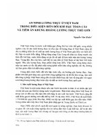
The sandwich toroidal shell segment of thickness h, length L, which is formed by rotation
of a plane circular arc of radius R about an axis in the plane of the curve is shown in Figure 1.
The coordinate system (x, y, z) is located on the middle surface of the shell, x and y is the
axial and circumferential directions, respectively and z is the normal to the shell surface. The
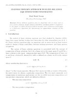
thickness of the shell is defined in a coordinate system (y, z) in Fig. 2. In this paper, FGM
core and ceramic core structures are investigated.
For FGM core, the inner layer (z = h/2) and the outer layer (z = -h/2) are isotropic
homogenous with ceramic and metal, respectively. Suppose that the material composition of
the shell varies smoothly along the thickness in such a way that the inner surface is ceramic,
the outer surface is metal and the core is FGM.
For ceramic core, the inner layer (z = h/2) and the outer layer (z = -h/2) are metal when
supposing that the material composition of the shell varies smoothly along the thickness from
ceramic core to outside metal.
The thickness of the shell is h, ceramic-rich and metal rich are h c, h m, respectively for
FGM core and FGM coatings are hz1 and hz2 as in Fig.2. The subscripts m and c are refered to
the metal and ceramic constituents respectively. Denote Vm and Vc as volume - fractions of
metal and ceramic phases respectively, where Vm + Vc = 1. According to the mentioned law,
the volume fraction is expressed as
For FGM core:
Vc ( z ) = 0,
k
z + h / 2 − hm
,
Vc ( z ) =
h − hc − hm
Vc ( z ) = 1,
−
h
h
≤ z ≤ − − hm
2
2
h
h
− − hm ≤ z ≤ − hc , k ≥ 0
2
2
h
h
− hc ≤ z ≤
2
2
(1)
For ceramic core:
6
k
z −h/2
,
Vc ( z ) =
− hz1
Vc ( z ) = 1,
k
z + h/2
,
Vc ( z ) =
hz 2
h
h
− hz1 ≤ z ≤ , k ≥ 0
2
2
h
h
− − hz 2 ≤ z ≤ − hz1 ,
2
2
h
h
− ≤ z ≤ − − hz 2
2
2
(2)
According to the mentioned law, the Young modulus, the mass density and the thermal
expression coefficient of FGM core shell are expressed of the form respectively
E ( z ) = EmVm ( z ) + EcVc ( z ) = E m + ( Ec − E m )Vc ( z ) ,
ρ ( z ) = ρ mVm ( z ) + ρcVc ( z ) = ρ m + ( ρ c − ρ m )Vc ( z ) ,
α ( z ) = α mVm ( z ) + α cVc ( z ) = α m + (α c − α m )Vc ( z )
the Poisson’s ratio ν is assumed to be constant.
Fig.1. The coordinate system of ES-FGM core toroidal shell segment containing fluid
a
b
7
Fig.2. The material properties of FGM sandwich:a) FGM core; b) ceramic core
2.2. Constitutive relations and governing equations
2.2.1. Constitutive relations
A sufficiently shallow toroidal shell segment in the region of the equator of the torus is
analyzed in Ref [28-35].
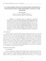
The eccentrically stiffened FGM sandwich toroidal shell segment is reinforced by string
and ring stiffeners. In order to provide continuity within the shell and stiffeners and easier
manufacture, the homogeneous stiffeners can be used. Since pure ceramic ones are brittleness
metal stiffener are used and put at metal side of the shell. With the indicated law in (1) and
(2), the outer surface is metal, so the external metal stiffeners are put at outer side of the shell.
Fig. 3 describes the geometry and coordinate system of stiffened FGM core shell.
(a)
(b)
Fig 3. Geometry and coordinate system of a stiffened FGM sandwich toroidal shell segment
containing fluid (a) stringer stiffeners; (b) ring stiffeners
The von Karman type nonlinear kinematic relation for the strain component across the shell
thickness at a distance z from the middle surface are of the form [36]:
ε x ε x0 χ x
0
ε y = ε y − z χ y ,
γ γ 0 2χ
xy z xy
(3)
0
0
where ε x0 and ε y are normal strains, γ xy is the shear strain at the middle surface of the shell
and χ x and χ y are the curvatures and χ xy is the twist.
According to the classical shell theory the strains at the middle surface and curvatures are
related to the displacement components u, v, w in the x, y, z coordinate directions as [36]:
2
∂u w 1 ∂w ∂w ∂wo
− + +
∂x R 2 ∂x
∂x ∂x
ε x0
2
0
∂v w 1 ∂w ∂w ∂wo
− + +
εy =
;
∂y a 2 ∂y
∂y ∂y
γ 0
xy ∂u ∂v ∂w ∂w ∂w ∂wo ∂w ∂wo
∂y + ∂x + ∂x ∂y + ∂x ∂y + ∂y ∂x
∂ 2w
2
χ x ∂x2
∂ w
χy = 2 ,
χ ∂y
xy ∂ 2 w
∂x∂y
(4)
8
where wo(x, y) is a known function representing initial imperfection of the shell.
From Eqs. (4) the strains must be satisfied in the deformation compatibility equation
2
2 0
2 0
∂ 2 ε x0 ∂ ε y ∂ γ xy
∂ 2 w ∂ 2 w ∂ 2 w ∂ 2 wo ∂ 2 w ∂ 2 wo
−
+
−
=
−
−
+
+
+
∂y 2
∂x 2
∂x∂y
R∂y 2 a∂x 2 ∂x∂y ∂x∂y ∂x 2
∂x 2
∂ 2 w ∂ 2 wo
2 +
∂y 2
∂y
. (5)
Hooke’s law for toroidal shell segment is defined as
E ( z)
E ( z )α ( z )
(ε x + νε y ) +
∆T , ∆T = T − T0 ,
2
1 −ν
1 −ν
E ( z)
E ( z )α ( z )
=
(ε y + νε x ) +
∆T ,
2
1 −ν
1 −ν
E ( z)
=
γ xy ,
2(1 +ν )
σ xsh =
σ ysh
σ xysh
(6)
and for metal stiffeners
st
σ xst = E m ε x + E mα m ∆T ; σ y = Emε y + Emα m∆T .
By intergrating the stress – strain equations and their moments through the thickness of the
shell and using the smeared stiffeners technique; the expressions for force and moment
resultants of a FGM core toroidal shell segment can be obtained as [33, 36]:
E A
N x = A11 + m 1 ε x0 + A12ε y0 − ( B11 + C1 ) χ x − B12 χ y + Φ a + Φ*a ,
s1
E A
N y = A12ε x0 + A22 + m 2 ε y0 − B12 χ x − ( B22 + C2 ) χ y + Φ a + Φ*a* ,
s2
N xy = A66γ xy0 − 2 B66 χ xy ,
E I
M x = ( B11 + C1 )ε x0 + B12ε 0y − D11 + m 1 χ x − D12 χ y + Φ m + Φ *m ,
s1
E I
M y = B12ε x0 + ( B22 + C2 )ε 0y − D12 χ x − D22 + m 2 χ y + Φ m + Φ*m* ,
s2
(7)
(8)
M xy = B66γ xy0 − 2 D66 χ xy ,
where Aij , B ij , D ij (i, j = 1, 2, 6) are extensional, coupling and bending stiffenesses of the
shell without stiffeners.
9
E1ν
,
1 −ν 2
Eν
B12 = 2 2 ,
1 −ν
Eν
D12 = 3 2 ,
1 −ν
E1
,
1 −ν 2
E2
B11 = B22 =
,
1 −ν 2
E3
D11 = D22 =
,
1 −ν 2
A11 = A22 =
E1
,
2(1 + ν )
E2
B66 =
,
2(1 + ν )
E3
D66 =
,
2(1 + ν )
A12 =
A66 =
(9)
where
For FGM core
h/2
∫ E ( z)dz = E
E1 =
m
h + Ecm hc +
−h / 2
h/ 2
∫ E ( z ) zdz =
E2 =
−h / 2
Ecm hc h Ecm hc2 Ecm h
Ecm
+
(h-hc -hm )2 ,
− hc (h-hc -hm )2
2
k +1 2
(k + 1 )(k + 2 )
2
h/ 2
∫ E ( z) z
E3 =
Ecm(h − hc − hm )
,
k +1
2
dz =
−h / 2
E cm h
2 Ecm
2 Ecm
E h3
h
2
(h-hc -hm )3 + c c
− hc (h-hc -hm ) −
− hc (h-hc -hm ) +
k + 1 2
(k + 1 )(k + 2 ) 2
(k + 1 )(k + 2 )(k + 3 )
3
E hh h
3hhm h
E
E
h
h
3
+ c c − hc + m hm3 +
− hm + m (h-hc -hm ) − 3 − hm − hc (h − hc − hm )
2 2
2 2
3
3
2
2
For ceramic core
h/2
∫ E( z)dz = E h − E
E1 =
c
cm
( hz1 + hz 2 ) +
−h / 2
Ecm (hz1 + hz 2 )
,
k +1
h/ 2
∫ E( z ) zdz = 0,
E2 =
−h / 2
h 2 hz 2 h 2 hz22 hz32
2
E
(
z
)
z
dz
=
E
−
+
m
∫
2
3
4
−h / 2
h/ 2
E3 =
2
h
2hz22
2hz32
h
h
+ Ecm − hz 2 z 2 + Ecm
− hz 2 + Ecm
( k + 1)(k + 2) 2
(k + 1)(k + 2)(k + 3)
2
k +1
2
h2
h 2 hz1 h 2 hz21 hz31
h h
2hz21
h
h
+ E cm z1 − hz1 + Ecm
+ Ec (hz 2 − hz1 ) − (hz22 − hz21 ) + hz32 − hz31 + Em
−
+
− hz1
2
2
3
k +1 2
(k + 1)(k + 2) 2
4
4
3
2hz1
+ Ecm
(k + 1)(k + 2)(k + 3)
in which Ecm = Ec - Em
C1 = −
Em A1 z 1
E Az
, C2 = − m 2 2 ,
s1
s2
A1 = h1 d 1 , A2 = h 2 d 2 ,
I1 =
d1h13
d h3
+ A1 z12 , I 2 = 2 2 + A2 z 22 .
12
12
Φa =
1
1 −ν
h/2
*
∫ E ( z )α ( z )∆Tdz ; Φ a =
−h / 2
d1
s1
−h / 2
**
∫ E mα m ∆Tdz ; Φ a =
− h / 2 − h1
d2
s2
−h / 2
∫E
m
α m ∆Tdz ;
− h / 2− h2
10
1
Φm =
1 −ν
h/ 2
d
E ( z )α ( z )∆Tzdz ; Φ = 1
∫
s1
−h / 2
*
m
If ∆T = const, Φ a =
−h / 2
d
E mα m ∆Tzdz ; Φ = 2
∫
s2
− h / 2 − h1
**
m
−h / 2
∫E
m
− h / 2− h2
α m ∆Tzdz.
dh
1
d h
Ph∆T ; Φ *a = 1 1 E mα m ∆T ; Φ *a* = 2 2 E mα m ∆T .
1 −ν
s1
s2
where for FGM core:
P = Emα m h + Ecα c hc + Emα m (h − hc ) +
Emα cm (h − hc − hm ) Ecmα m (h − hc − hm ) Ecmα cm (h − hc − hm )
+
+
.
k +1
k +1
2k + 1
and for ceramic core:
P = Emα m (hz1 + hz 2 ) + Ecα c (h − hz1 − hz 2 ) +
Emα cm (hz1 + hz 2 ) Ecmα m (hz1 + hz 2 ) Ecmα cm (hz1 + hz 2 )
+
+
.
k +1
k +1
2k + 1
The spacings of the stringer and ring stiffeners are denoted by s1 and s2 respectively. The
quantities A1, A2 are the cross section areas of the stiffeners and I1, I2, z1, z2 are the second
moments of cross section areas and eccentricities of the stiffeners with respect to the middle
surface of the shell respectively.
The reverse relations are obtained from Eqs. (7)
*
*
ε x0 = A22* N x − A12* N y + B11* χ x + B12* χ y + ( A12* − A22
)Φ a − A22
Φ*a + A12* Φ*a* ,
*
*
ε y0 = A11* N y − A12* N x + B21
χ x + B22
χ y + ( A12* − A11* )Φ a − A11* Φ*a* + A12* Φ*a ,
(10)
γ xy0 = A66* N xy + 2 B66* χ xy .
Substituting Eqs. (10) into Eqs. (8) yields
[
*
*
*
M x = B11* N x + B21
N y − D11* χ x − D12* χ y + (B11 + C1 ) ( A12* − A22
)Φ a − A22
Φ *a + A12* Φ *a*
[
]
]
+ B12 ( A12* − A11* )Φ a − A11* Φ *a* + A12* Φ *a + Φ m + Φ *m ,
[
]+ Φ
]
*
*
*
*
*
M y = B12* N x + B22
N y − D21
)Φ a − A22
Φ *a + A12* Φ *a* +
χ x − D22
χ y + B12 ( A12* − A22
[
+ ( B22 + C2 ) ( A − A )Φ a − A Φ + A Φ
*
66
*
12
*
11
*
11
**
a
*
12
*
a
m
(11)
**
m
+Φ ,
*
66
M xy = B N xy − 2 D χ xy ,
where
11
A11* =
1
E A
1
E A
*
A11 + m 1 , A22
= A22 + m 2 ,
∆
s1
∆
s2
A12* =
A12
,
∆
*
A66
=
1
,
A66
E A
E A
∆ = A11 + m 1 . A22 + m 2 − A122 ;
s1
s2
*
*
*
*
B11 = A22 ( B11 + C1 ) − A12 B12 ,
B22
= A11* ( B22 + C 2 ) − A12* B12 ,
*
B12* = A22
B12 − A12* ( B22 + C2 ),
D11* = D11 +
*
D22
= D22 +
*
B21
= A11* .B12 − A12* ( B11 + C1 ),
*
B66
=
B66
.
A66
Em I1
*
− ( B11 + C1 ) B11* − B12 B21
,
s1
Em I 2
*
*
− B12 B21
− ( B22 + C2 ) B22
,
s2
*
D12* = D12 − ( B11 + C1 ) B12* − B12 B22
,
*
*
D21
= D12 − B12 B11* − ( B22 + C 2 ) B21
,
*
*
D66
= D66 − B66 B66
.
2.2.2.
Governing equations
Consider a toroidal shell segment filled inside by an incompressible fluid and subjected to a
lateral pressure q(t) varying on time. Under this mechanical load the shell and fluid will
vibrate simultaneously, moreover the fluid reacts on the shell by a dynamic fluid pressure pL .
The nonlinear motion equations of the considered shell based on the classical shell theory are
given by [36]:
∂N x ∂N xy
∂ 2u
+
= ρ1 2 ,
∂x
∂y
∂t
∂N xy ∂N y
∂2v
+
= ρ1 2 ,
∂x
∂y
∂t
∂ 2 M xy ∂ 2 M y
∂ 2 w ∂ 2 wo
∂ 2 w ∂ 2 wo
∂2M x
+ 2 N xy
+2
+
+ N x 2 +
+
2
2
2
∂x∂y
∂x
∂y
∂x
∂x
∂x∂y ∂x∂y
∂ 2 w ∂ 2 wo N x N y
∂2w
∂w
+ N y 2 +
+
+
+ q = ρ1 2 + 2 ρ1ε
- pL ,
2
a
∂t
∂y R
∂t
∂y
(12)
where ε is damping coefficient, and
ρ1 = ρ m h + ρ cm hc +
ρ cm(h − hc − hm )
ρ1 = ρ m (hz1 + hz 2 ) +
k +1
A A
+ ρ m 1 + 2 for FGM core
s1 s2
A A
ρ cm (hz1 + hz 2 )
+ ρ c (h − hz1 − hz 2 ) + ρ m 1 + 2 for ceramic core
k +1
s1 s2
(13)
(14)
The dynamic pressure of fluid pL acting on the shell is expressed as follows:
12
pL = −ρ L
∂ϕ L
,
∂t
(15)
where ρL is the mass density of fluid and ϕ L is the fluid velocity potential.
According to the Stein-McElman assumption [29], for a shallow toroidal shell segment the
equation of the fluid velocity potential can be written approximately in the cylindrical
coordinate system (x, θ, r)
∂ 2ϕ L 1 ∂ϕ L
1 ∂ϕ L ∂ 2ϕ L
+
+
+
+
=0
r 2 ∂θ 2 ∂x 2
∂r 2 r ∂r
(16)
∂ϕ L
∂w
=−
at r = a;
∂r
∂t
(17)
with boundary condition:
ϕ L has to be finite when r = 0 and at x = 0; L it depends on boundary condition of the shell.
Suppose the shell is simply supported at x = 0 and x = L the vibration shape function of shell
can be chosen as
w = ∑∑ f mn (t ) sin
mπx
sinnθ ,
L
(18)
Then the solution of Eq. (16) can be expressed as following:
mπr mπx
sinnθ ,
sin
L
L
ϕ L = ∑∑ Amn (t ) I n
(19)
in which In is Bessel’s function of the first kind of order n.
Certainly substitution Eq. (19) into the left side of Eq. (16), leads to the identity. Satisfying
boundary condition (17) with the use of Eqs. (18) (19), we obtain
Amn (t ) =
−L
df mn
.
' mπa dt
mπI n
L
Putting just obtained result into Eq. (19) and comparing with Eq. (18) yields
ϕL = −
mπa
aI n ( λm ) ∂w
, ( λm =
).
'
L
λ m I n ( λ m ) ∂t
(20)
Substituting Eq. (20) into the left side of Eq. (15), the expression of dynamic fluid pressure
acting on the shell is obtained:
13
pL = − ρ L
∂ϕ L
aI n (λm ) ∂ 2 w
∂2w
,
= ρL
=
m
L
∂t
λm I n' (λm ) ∂t 2
∂t 2
(21)
ρ L aI n (λ m )
( where mL is the mass of fluid corresponding to the vibration of
λ m I n' (λ m )
shell; so-called “added mass effect”)
in which m L =
Putting the expression of dynamic fluid pressure (21) into Eqs. (12) and using the Volmir’s
assumption [37] ρ1 (d 2U / dt 2 ) → 0 , ρ1 (d 2V / dt 2 ) → 0 because of u << w , v << w , we can
rewrite the system of motion equations (12) as follows:
∂N x ∂N xy
+
= 0,
∂x
∂y
∂N xy ∂N y
+
= 0,
∂x
∂y
∂ 2 M xy ∂ 2 M y
∂ 2 w ∂ 2 wo
∂ 2 w ∂ 2 wo
∂ 2 w ∂ 2 wo N x N y
∂2M x
∂ 2w
∂w
+ 2 N xy
+ N y 2 +
+
+2
+
+ N x 2 +
+
+
+ q = ( ρ1 + m L ) 2 + 2 ρ1ε
.
2
2
2
2
∂x
∂x∂y
∂y
∂
x
∂
x
∂
x
∂
y
∂
x
∂
y
∂
y
∂
y
R
a
∂
t
∂t
(22)
Two first equations of Eqs. (22) are satisfied identically by introducing the stress function as:
Nx =
∂2 F
,
∂y 2
Ny =
∂2F
,
∂x 2
N xy = −
∂2F
.
∂x∂y
(23)
Substituting Eqs. (21) into deformation compatibility equation (5) and substituting Eqs. (11)
into the third equation of motion (22), taking into account expressions (4) and (23), yields a
system of equations:
A11*
4
4
∂4F
∂4F
∂4w
∂ 4w 1 ∂2w
*
* ∂ F
* ∂ w
*
*
+ ( A66
− 2 A12* ) 2 2 + A22
+ B21
+ ( B11* + B22
− 2 B66
) 2 2 + B12*
+
+
4
4
4
∂x
∂x ∂y
∂y
∂x
∂x ∂y
∂y 4 R ∂y 2
2
1 ∂ 2 w ∂ 2w ∂ 2w ∂ 2 w
∂ 2 w ∂ 2 wo ∂ 2 w ∂ 2 wo ∂ 2 w ∂ 2 wo
+
+
+
−
2
+
+ 2
= 0,
a ∂x 2 ∂x∂y
∂x 2 ∂y 2
∂x∂y ∂x∂y ∂x 2 ∂y 2
∂y ∂x 2
(24)
(ρ 1 + m L ) ∂
2
w
∂t 2
− B12*
+ 2 ρ1ε
4
4
∂w
∂4w
∂4w
∂4F
*
*
*
* ∂ w
* ∂ F
*
*
*
+ D11*
+
(
D
+
D
+
4
D
)
+
D
−
B
−
(
B
+
B
−
2
B
)
12
21
66
22
21
11
22
66
∂t
∂x 4
∂x 2 ∂y 2
∂y 4
∂x 4
∂x 2 ∂y 2
∂ 4 F 1 ∂ 2 F 1 ∂ 2 F ∂ 2 F ∂ 2 w ∂ 2 wo
∂ 2 F ∂ 2 w ∂ 2 wo ∂ 2 F ∂ 2 w ∂ 2 wo
−
= q.
−
−
−
+
+
2
+
+
∂y 4 R ∂y 2 a ∂x 2 ∂y 2 ∂x 2
∂x 2
∂x∂y ∂x∂y ∂x∂y ∂x 2 ∂y 2
∂y 2
(25)
Eqs. (24) and (25) are the nonlinear governing equations used to investigate the nonlinear
vibration of full-filled fluid imperfect eccentrically stiffened FGM core toroidal shell
segments.
3. Nonlinear thermal vibration of full-filled fluid imperfect FGM sandwich toroidal
shell segments
14
Suppose that the shell is simply supported at its edges and acted on by a lateral pressure q and
a pre-axial compression p. The boundary conditions can be expressed as:
w = 0, Mx = 0, Nx = -ph, Nxy = 0 at x = 0; L
Satisfying these conditions the deflection and the imperfection of the shell can be chosen in
the form
w = f (t ) sin γ m x sin β n y ,
wo = f o sin γ m x sin β n y ,
(26)
mπ
n
; βn =
and m, n are the half waves numbers along x-axis and waves
2a
L
numbers along y-axis, respectively,
where γ m =
f o is constant, f o can be put as: f o = µh ( 0 ≤ µ < 1 ), h is the thickness of shell.
Substituting Eq. (26) into the left side of Eq. (24), the solution for stress function F of this
equation can be expressed as:
F = F1 cos 2γ m x + F2 cos 2β n y − F3 sin γ m x sin β n y + N 01
y2
x2
+ No 2 ,
2
2
(27)
where N01 = -poh is the pre-axial compression load, No2 is the negative average
circumferential load and
F1 = F1* f ( f + 2 f o ) ;
F2 = F2* f ( f + 2 f o ) ;
F3 = F3* f ,
F1* =
β n2
8γ m2 A11*
F2* =
γ m2
*
8β n2 A22
F3* =
* 4
*
*
B21
− 2 B66
)γ m2 β n2 + 16 B12* β n4 − 4β n2 / R − γ m2 / a
γ m + 2( B11* + B22
.
*
*
A11* γ m4 + 2( A66
− 2 A12* )γ m2 β n2 + 16 A22
β n4
Furthermore, the toroidal shell segments have to satisfy the circumferential closed condition
[20] as:
15
L 2πa
∫∫
0 0
L 2πa
∂v
dxdy = ∫
∂y
0
∫
0
0 w 1 ∂w 2 ∂w ∂w
o
ε y + − −
dxdy = 0
a
2
∂
y
∂
y
∂
y
(28)
Using Eqs. (10) (23) (26) and (27), the integral becomes:
A11* γ m F3*δ 1δ 2
βn
−
2
n
β Lπa
4
f + 2 N o 2 A11* Lπa −
f2−
2
n
β Lπa
2
A12* β n F3*δ1δ 2
γm
f − 2 N o1 A12* Lπa −
[
*
γ mδ1δ 2
B21
βn
f −
*
β nδ1δ 2
B22
γm
δ1δ 2
f
aγ m β n
f +
]
f o f + 2 ( A12* − A11* )Φ a − A11* Φ*a* + A12* Φ *a Lπa = 0
(29)
from which to give:
N o2 =
β n2
8 A11*
f 2 + ψf + N o1
A12*
−Ω
A11*
(30)
where
*
*
A11* γ m F3*δ1δ 2 A12* β n F3*δ1δ 2 B21
1
γ mδ1δ 2 B22
β nδ1δ 2 δ 1δ 2
β n2 Lπa
ψ= *
−
+
+
+
−
+
f o
βn
γm
βn
γm
2 A11Lπa
aγ m β n
2
*
*
*
**
*
*
*
Ω = ( A12 − A11 )Φ a − A11Φ a + A12 Φ a / A11
[
]
δ 1 = ( −1) m − 1 and δ 2 = (−1) n − 1
Substituting Eq. (30) into Eq. (27) yields
F = F1 cos 2γ m x + F2 cos 2β n y − F3 sin γ m x sin β n y + N o1
x2
y 2 β n2 2
A*
+ * f +ψf + N o1 12* − Ω
2 8 A11
A11
2
(31)
Substituting Eq. (26) and (31) into Eq. (25) and then applying Galerkin’s procedure in the
range 0 ≤ x ≤ L ; 0 ≤ y ≤ 2πa , we obtain the following equation:
δδ
A*
A*
∂f
+ U 1 f 3 + U 2 f 2 + U 3 f + N o1 γ m2 + 12* β n2 f + Ωβ n2 f + N o1 γ m2 + 12* β n2 f o − N o1 1 2
γ
∂t
∂t
A
A
mβn
11
11
δδ 2
δδ
2
−q 1 2
+ Ωβ n2 f o − Ω 1 2
=0
γ m β n Lπa
γ m β n Lπa 2
(ρ 1 + m L ) ∂
2
f
2
+ 2 ρ1ε
1 A12* 2
+ *
R aA11 Lπa
(31)
in which
16
U 1 = 2γ m2 β n2 ( F1* + F2* ) + β n4 / 8 A11* ;
U 2 = 6γ m2 β n2 f o ( F1* + F2* ) +
+ ψβn2 +
β n4
8 A11*
fo −
βn
2δ1δ 2
4γ 2 F * 4β 2 F * 20 γ m β nδ1δ 2 F3*
*
16F1*γ m4 B21
+ 16F2*β m4 B12* − m 1 − m 2 +
+
3γ m β n Lπa
a
R 9
Lπa
δ1δ 2
4 A11* aγ m Lπa
*
*
* 4 *
*
*
U 3 = D11* γ m4 + ( D12* + D21
+ 4D66* )γ m2 β n2 + D22
− 2B66
)γ m2 β n2 F3* + B12* β n4 F3* −
β n4 + B21
γ m F3 + ( B11* + B22
+ 4γ m2 β n2 f o2 ( F1* + F2* ) +
β n2
R
F3* −
γ m2
a
F3*
4δ 1δ 2 f o
4γ 2 F * 4β 2 F * 20 γ m β nδ 1δ 2 f o F3*
2δ 1δ 2
*
16 F1*γ m4 B21
+ 16 F2* β m4 B12* − m 1 − m 2 +
+ ψβ n2 f o −
ψ
3γ m β n Lπa
a
R 9
Lπa
aγ m β n Lπa
The fundamental frequencies of the shell can be drawn from Eq. (31) as follows:
ωmn
A*
U 3 + N o1 γ m2 + 12* β n2 + Ωβ n2
A11
=
ρ1 + mL
(32)
Equation (31) is an equation of motion to investigate the nonlinear vibration of imperfect
stiffened FGM sandwich toroidal shell segments containing fluid. Using the fourth-order
Runge-Kutta method into Eq. (31) combined with initial conditions, the nonlinear dynamic
responses of full-filled fluid shells can be observed.
4. Results and discussion
4.1.
Validations
To the best of the authors’ knowledge, there are no any publications about thermal
vibration of imperfect three-layered toroidal shell segments containing full-filled fluid. Thus,
the results in this paper are compared with FGM cylindrical shell (i.e. a toroidal shell
segment with R → ∞) and hc = hm = 0.
Firstly, comparison of natural frequencies of perfect un-stiffened FGM cylindrical
shells without containing fluid are illustrated in Table 1a. Those were also compared with
these of Ref [18] using the energy method and Love’s shell theory. It is observed in Table 1
that very good agreements are obtained in this comparison.
Table 1a. Comparisons of natural frequencies (Hz) of perfect un-stiffened FGM cylindrical
shells
n
1
Source
Ref [18]
Present
∞
12.917
12.916
1/0.5
1/0.7
13.126 13.177
13.126 13.177
k
1/1
1/2
13.234 13.344
13.234 13.344
1/5
1/15
13.457 13.528
13.457 13.528
1/30
0
13.549 13.572
13.549 13.572
17
2
Ref [18]
Present
31.603
31.687
32.151 32.277
32.231 32.331
32.418 32.683
32.467 32.731
32.959 33.157
33.007 33.186
33.221 33.296
33.239 33.298
3
Ref [18]
Present
88.267
88.566
89.818 90.173
90.000 90.347
90.569 91.309
90.742 91.499
92.075 92.617
92.274 92.766
92.795 93.001
92.911 93.064
4
Ref [18]
Present
168.99
169.48
171.97 172.65
172.31 172.94
173.41 174.83
173.66 175.06
176.29 177.33
176.54 177.50
177.66 178.06
177.79 178.09
5
Ref [18]
Present
273.14
273.90
277.95 279.05
278.34 279.41
280.28 282.57
280.61 282.94
284.93 286.61
285.34 286.88
287.15 287.79
287.33 287.82
Secondly, the natural frequencies of isotropic full-filled fluid cylindrical shells in
Table 1b are computed and compared with the results of Pellicano and Amabili. [38] using
continuation techniques and direct simulations based on geometric nonlinearities with the
Donnell’s nonlinear shallow-shell theory. As can be seen, a very good agreement is obtained
in the comparison with the results of Ref [38].
Table 1b. Comparisons of natural frequencies (rad/s) of ful-filled fluid cylindrical shells
Natural frequencies (rad/s)
ω1,5
ω3,5
ω 1,15
ω3,15
4.2.
Ref [38]
1704.36
7446.14
13107.4
14473.5
Present
1764.39
7791.32
13305.69
15314.89
Nonlinear thermal vibration of toroidal shell segments
In next sections, thermal vibration of imperfect three-layered toroidal shell segments
containing fluid under mechanical loads and effects of geometrical parameters, imperfections,
fluid and temperature are considered. The Aluminum and Alumina materials are used with
Em = 70 × 109 N / m 2 ; ρ m = 2702 kg/m3;
α m = 23 ×10 −6 0C −1 ;
Ec = 380× 109 N / m 2 ;
ρ c = 3800 kg/m3; α c = 5.4 ×10 −6 0C −1 and Poisson’s ratio is chosen to be 0.3. The density of
fluid is chosen ρL = 1000 kg/m3. The parameters n1 = 50 and n2 = 50 are the number of
stringer and ring stiffeners, respectively and the some parameters are confirm as: h1=h/2;
h2=h/2; d2=h/2;d1=h/2.
Fundamental frequencies
The geometrical parameters of problem are given as follows:
h = 0.01m; hc = 0.2h; hm = 0.1h; h1=h/2; h2=h/2; d2=h/2;d1=h/2; a = 200h; R = 400h; L = 2a.
18
Table 2 and Table 3 describe fundamental frequencies of FGM core convex shell and
concave shell without fluid and full-filled fluid under pre-axial compression load,
respectively. As can be seen, the fundamental frequencies of FGM core shells without fluid
are much more over 10 times than those of full-filled fluid FGM core shells and those of
FGM core will reduce under pre-axial compression load. In addition, the lowest frequencies
corresponding to mode of vibration of convex shell and concave shell are (m, n) = (1, 15) and
(m, n) = (1, 5), respectively. This is an essential factor to choose mode for investigating in
next sections. The paper will use these modes to investigate the thermal vibration of
imperfect full-filled fluid three-layered FGM toroidal shell segments.
Table 2. Fundamental frequencies of convex shell without fluid and full-filled fluid under
pre-axial compression load (m=1).
p
0
1 MPa
n
No
fluid
Fullfilled
fluid
No
fluid
Fullfilled
fluid
1
4206.59
3
2303.35
5
1625.10
7
1373.77
9
1258.39
11
1200.78
13
1174.82
15
1170.93
17
1185.82
19
1218.74
376.24
206.01
145.35
122.87
112.55
107.40
105.08
104.73
106.06
109.00
4206.58
2303.30
1624.99
1373.60
1258.14
1200.42
1174.34
1170.32
1182.05
1217.83
376.20
206.00
145.33
122.85
112.52
107.36
105.03
104.67
105.99
108.92
Table 3. Fundamental frequencies of concave shell without fluid and full-filled fluid under
pre-axial compression load (m = 1).
p
0
1 MPa
n
No
fluid
Fullfilled
fluid
No
fluid
Fullfilled
fluid
1
3852.05
3
955.86
5
801.39
7
897.32
9
957.19
11
997.14
13
1031.13
15
1067.13
17
1110.25
19
1164.09
344.53
85.49
71.68
80.26
85.61
89.18
92.22
95.44
99.30
104.12
3852.02
955.74
801.19
897.07
956.85
996.71
1030.58
1066.46
1109.44
1163.14
344.52
85.48
71.65
80.23
85.58
89.14
92.17
95.38
99.23
104.03
Effect of R/h
Fig. 4 and Fig. 5 express the effect of R/h ratio on nonlinear vibration of imperfect FGM
core convex shell with full-filled fluid and without fluid in turn while Fig. 6 and Fig. 7 depict
the effect of R/h ratio on nonlinear vibration of imperfect FGM core concave shell similarly.
When increasing R/h ratio, the amplitudes of nonlinear vibration of both imperfect FGM core
convex and concave shell increase in both no fluid and full-filled fluid. Based on four
Figures, there are three pivotal points. Firstly, because the number of responses of full-filled
fluid shell is lower than that of shell without fluid, the frequencies of full-filled fluid FGM
core shell are lower than those of FGM core shell without fluid. Secondly, the amplitudes of
19
vibration responses of concave shells are always higher than those of convex shells. Finally,
due to “added mass effect” of fluid inversing the direct of pressure load, the amplitudes of
both full-filled fluid convex and concave shells are lower than those of no-fluid shells.
Figure 4. Effect of R/h on nonlinear vibration response of full-filled fluid imperfect FGM
core convex shell
20
Figure 5. Effect of R/h on nonlinear vibration response of imperfect FGM core convex shell
without fluid
Figure 6. Effect of R/h on nonlinear vibration response of full-filled fluid imperfect FGM
core concave shell
21
Figure 7. Effect of R/h on nonlinear vibration response of imperfect imperfect FGM core
concave shell without fluid
Effect of L/R
The effect of L/R ratio is illustrated in from Fig. 8 to Fig. 11. Obviously, the amplitudes of
imperfect FGM core concave shell are always higher than those of convex shell with the
same properties. As can be seen, similarly with effect of R/h, the “ add mass effect” decreases
the vibration amplitudes and the frequencies of both full-filled fluid convex and concave
shells; further the longer the shells are, the higher the amplitudes are for convex shell.
However, this feature of concave shell is contrarily.
Figure 8. Effect of L/R on nonlinear vibration response of full-filled fluid imperfect FGM
core convex shell
22
Figure 9. Effect of L/R on nonlinear vibration response of imperfect FGM core
convex shell without fluid
Figure 10. Effect of L/R on nonlinear vibration response of full-filled fluid imperfect FGM
core concave shell
23
Figure 11. Effect of L/R on nonlinear vibration response of imperfect FGM core
concave shell without fluid
Effect of ceramic layer
Figure 12. Effect of ceramic layer on nonlinear vibration response of imperfect FGM core
convex shell full-filled fluid and without fluid
24